Page 1290 of 3039
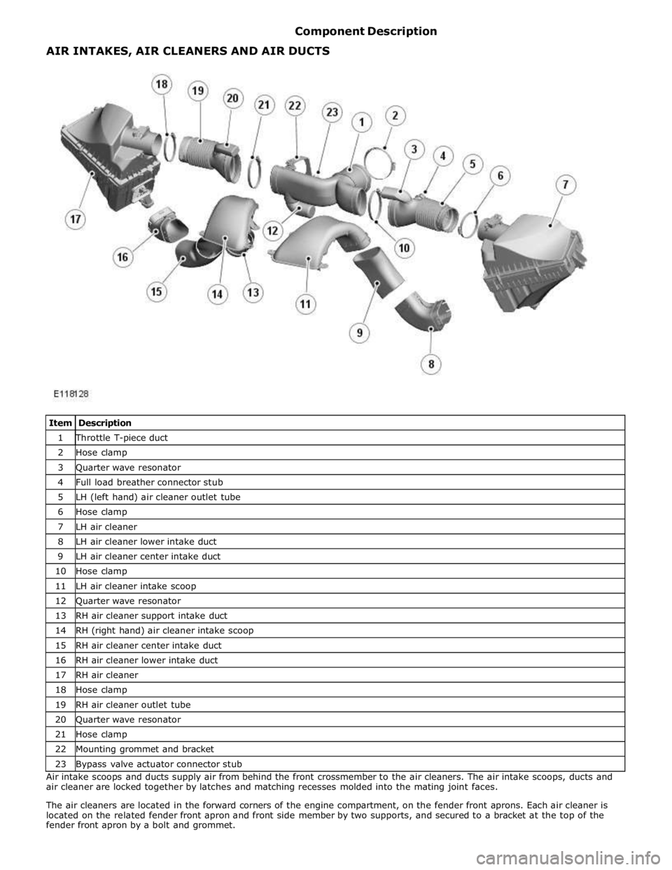
1 Throttle T-piece duct 2 Hose clamp 3 Quarter wave resonator 4 Full load breather connector stub 5 LH (left hand) air cleaner outlet tube 6 Hose clamp 7 LH air cleaner 8 LH air cleaner lower intake duct 9 LH air cleaner center intake duct 10 Hose clamp 11 LH air cleaner intake scoop 12 Quarter wave resonator 13 RH air cleaner support intake duct 14 RH (right hand) air cleaner intake scoop 15 RH air cleaner center intake duct 16 RH air cleaner lower intake duct 17 RH air cleaner 18 Hose clamp 19 RH air cleaner outlet tube 20 Quarter wave resonator 21 Hose clamp 22 Mounting grommet and bracket 23 Bypass valve actuator connector stub Air intake scoops and ducts supply air from behind the front crossmember to the air cleaners. The air intake scoops, ducts and
air cleaner are locked together by latches and matching recesses molded into the mating joint faces.
The air cleaners are located in the forward corners of the engine compartment, on the fender front aprons. Each air cleaner is
located on the related fender front apron and front side member by two supports, and secured to a bracket at the top of the
fender front apron by a bolt and grommet. AIR INTAKES, AIR CLEANERS AND AIR DUCTS
Page 1292 of 3039
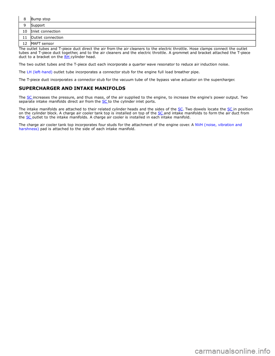
9 Support 10 Inlet connection 11 Outlet connection 12 MAFT sensor The outlet tubes and T-piece duct direct the air from the air cleaners to the electric throttle. Hose clamps connect the outlet
tubes and T-piece duct together, and to the air cleaners and the electric throttle. A grommet and bracket attached the T-piece
duct to a bracket on the RH cylinder head. The two outlet tubes and the T-piece duct each incorporate a quarter wave resonator to reduce air induction noise.
The LH (left-hand) outlet tube incorporates a connector stub for the engine full load breather pipe.
The T-piece duct incorporates a connector stub for the vacuum tube of the bypass valve actuator on the supercharger.
SUPERCHARGER AND INTAKE MANIFOLDS
The SC increases the pressure, and thus mass, of the air supplied to the engine, to increase the engine's power output. Two separate intake manifolds direct air from the SC to the cylinder inlet ports.
The intake manifolds are attached to their related cylinder heads and the sides of the SC. Two dowels locate the SC in position on the cylinder block. A charge air cooler tank top is installed on top of the SC and intake manifolds to form the air duct from the SC outlet to the intake manifolds. A charge air cooler is installed in each intake manifold.
The charge air cooler tank top incorporates four studs for the attachment of the engine cover. A NVH (noise, vibration and
harshness) pad is attached to the side of each intake manifold.
Page 1293 of 3039
1 Engine cover rear attachment points 2 Vacuum connector stub 3 MAPT (manifold absolute pressure and temperature) sensor 4 SC filler/level plug 5 Symposer inlet pipe connection 6 Dowels 7 Engine cover front attachment points 8 EVAP (evaporative emissions) connector stub 9 Part load breather connector stub 10 MAP (manifold absolute pressure ) sensor 11 Bypass valve pneumatic actuator 12 Outlet ports 13 Inlet port 14 Pulley 15 Coolant inlet and outlet connections Supercharger and Intake Manifolds - Assembled
Page 1295 of 3039
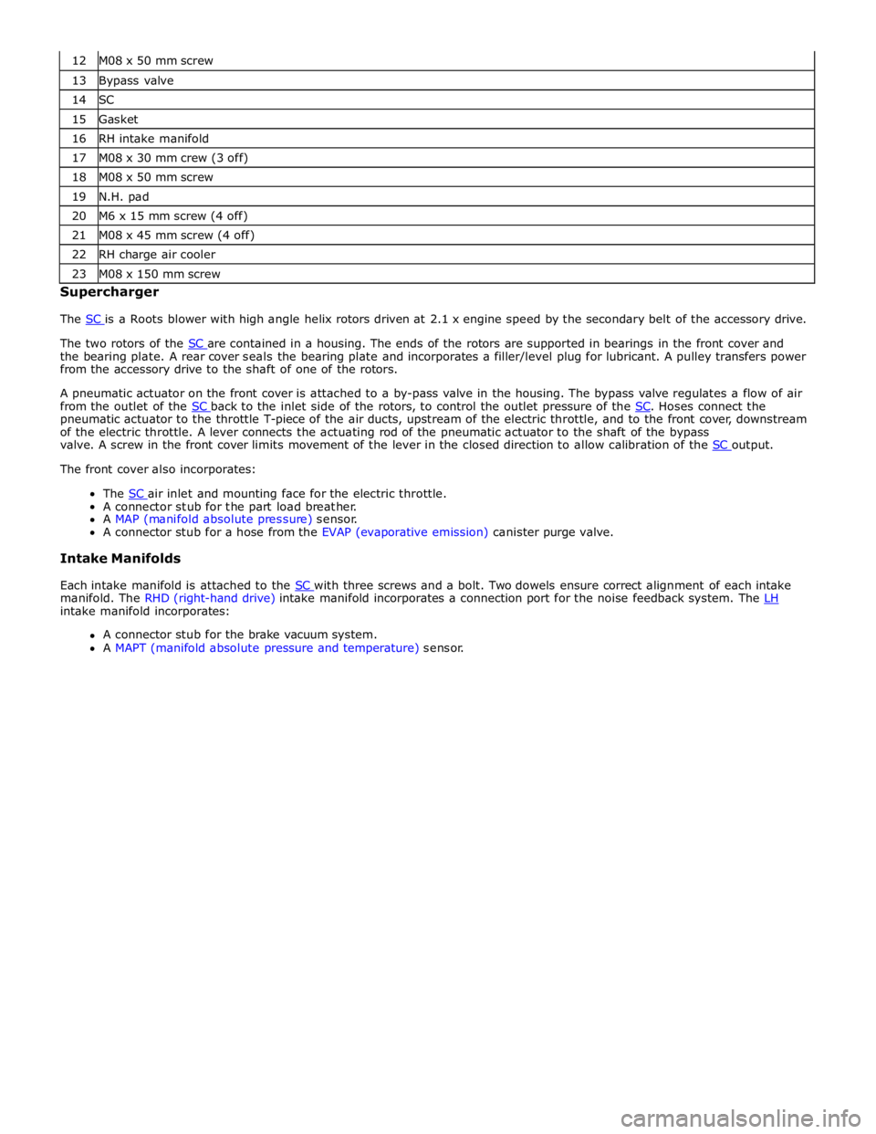
13 Bypass valve 14 SC 15 Gasket 16 RH intake manifold 17 M08 x 30 mm crew (3 off) 18 M08 x 50 mm screw 19 N.H. pad 20 M6 x 15 mm screw (4 off) 21 M08 x 45 mm screw (4 off) 22 RH charge air cooler 23 M08 x 150 mm screw Supercharger
The SC is a Roots blower with high angle helix rotors driven at 2.1 x engine speed by the secondary belt of the accessory drive.
The two rotors of the SC are contained in a housing. The ends of the rotors are supported in bearings in the front cover and the bearing plate. A rear cover seals the bearing plate and incorporates a filler/level plug for lubricant. A pulley transfers power
from the accessory drive to the shaft of one of the rotors.
A pneumatic actuator on the front cover is attached to a by-pass valve in the housing. The bypass valve regulates a flow of air
from the outlet of the SC back to the inlet side of the rotors, to control the outlet pressure of the SC. Hoses connect the pneumatic actuator to the throttle T-piece of the air ducts, upstream of the electric throttle, and to the front cover, downstream
of the electric throttle. A lever connects the actuating rod of the pneumatic actuator to the shaft of the bypass
valve. A screw in the front cover limits movement of the lever in the closed direction to allow calibration of the SC output. The front cover also incorporates:
The SC air inlet and mounting face for the electric throttle. A connector stub for the part load breather.
A MAP (manifold absolute pressure) sensor.
A connector stub for a hose from the EVAP (evaporative emission) canister purge valve.
Intake Manifolds
Each intake manifold is attached to the SC with three screws and a bolt. Two dowels ensure correct alignment of each intake manifold. The RHD (right-hand drive) intake manifold incorporates a connection port for the noise feedback system. The LH intake manifold incorporates:
A connector stub for the brake vacuum system.
A MAPT (manifold absolute pressure and temperature) sensor.
Page 1297 of 3039
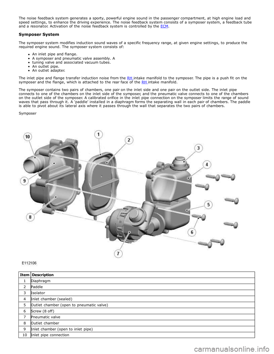
Symposer System
The symposer system modifies induction sound waves of a specific frequency range, at given engine settings, to produce the
required engine sound. The symposer system consists of:
An inlet pipe and flange.
A symposer and pneumatic valve assembly. A
tuning valve and associated vacuum tubes.
An outlet pipe.
An outlet adapter.
The inlet pipe and flange transfer induction noise from the RH intake manifold to the symposer. The pipe is a push fit on the symposer and the flange, which is attached to the rear face of the RH intake manifold.
The symposer contains two pairs of chambers, one pair on the inlet side and one pair on the outlet side. The inlet pipe
connects to one of the chambers on the inlet side of the symposer, and the pneumatic valve connects to one of the chambers
on the outlet side of the symposer. A calibrated orifice in the inlet pipe connection on the symposer limits the range of sound
waves that pass through it. A 'paddle' installed in a diaphragm forms the separating wall in each pair of chambers. The paddle
is able to pivot about its lateral axis where it passes through the wall that separates the two pairs of chambers.
Symposer
Item Description 1 Diaphragm 2 Paddle 3 Isolator 4 Inlet chamber (sealed) 5 Outlet chamber (open to pneumatic valve) 6 Screw (8 off) 7 Pneumatic valve 8 Outlet chamber 9 Inlet chamber (open to inlet pipe) 10 Inlet pipe connection
Page 1298 of 3039

The tuning valve controls the application of vacuum pressure to the pneumatic valve. Two screws attach the tuning valve to the
same bracket as the symposer and pneumatic valve. The tuning valve is a normally-closed solenoid-operated valve installed in
the vacuum line between a T-connection in the brake vacuum system and the pneumatic valve. A vent cap on the tuning valve
allows atmospheric pressure into the vacuum line to the pneumatic valve when the tuning valve is closed.
The outlet pipe carries sound from the pneumatic valve to the feedback tube via the outlet adapter. The outlet pipe is a push
fit on the pneumatic valve and in the outlet adapter. A screw attaches the outlet adapter to an engine harness bracket
installed between the two intake manifolds.
Feedback Tube
The feedback tube transfers the sound from the symposer system to the resonator. Clips secure the feedback tube to the
outlet adapter of the symposer system and to the resonator.
Resonator
The resonator directs the sound from the feedback tube into the passenger compartment. The resonator is installed in the
passenger compartment side of the engine bulkhead, on two mounting grommets each consisting of an isolator and a
compression limiter. A hose seal isolates the resonator where it passes through the secondary bulkhead.
Page 1311 of 3039
Published: 11-May-2011
Intake Air Distribution and Filtering - V8 S/C 5.0L Petrol - Air Cleaner Outlet Pipe T-Connector
Removal and Installation
Removal
NOTE: Removal steps in this procedure may contain installation details.
1. Refer to: Engine Cover - V8 5.0L Petrol/V8 S/C 5.0L Petrol (501-05 Interior Trim and Ornamentation, Removal and Installation).
Installation
2. Torque: 10 Nm
1. To install, reverse the removal procedure. www.JagDocs.com
Page 1312 of 3039
Published: 08-Nov-2013
Intake Air Distribution and Filtering - V8 S/C 5.0L Petrol - Charge Air Cooler
Removal and Installation
Removal
NOTE: Removal steps in this procedure may contain installation details.
1. WARNING: Make sure to support the vehicle with axle stands.
Raise and support the vehicle.
2. Refer to: Battery Disconnect and Connect (414-01 Battery, Mounting and Cables, General Procedures).
3. Refer to: Engine Cover - V8 5.0L Petrol/V8 S/C 5.0L Petrol (501-05 Interior Trim and Ornamentation, Removal and Installation).
4. Refer to: Secondary Bulkhead Center Panel (501-02 Front End Body Panels, Removal and Installation).
5. Refer to: Fuel Injection Component Cleaning (303-04D Fuel Charging and Controls - V8 5.0L Petrol, General Procedures).
6. Refer to: Cooling System Partial Draining, Filling and Bleeding - V8 S/C 5.0L Petrol (303-03C Engine Cooling - V8 5.0L Petrol/V8 S/C 5.0L Petrol, General Procedures).
7. Refer to: Fuel System Pressure Release - V8 5.0L Petrol/V8 S/C 5.0L Petrol (310-00 Fuel System - General Information, General Procedures).
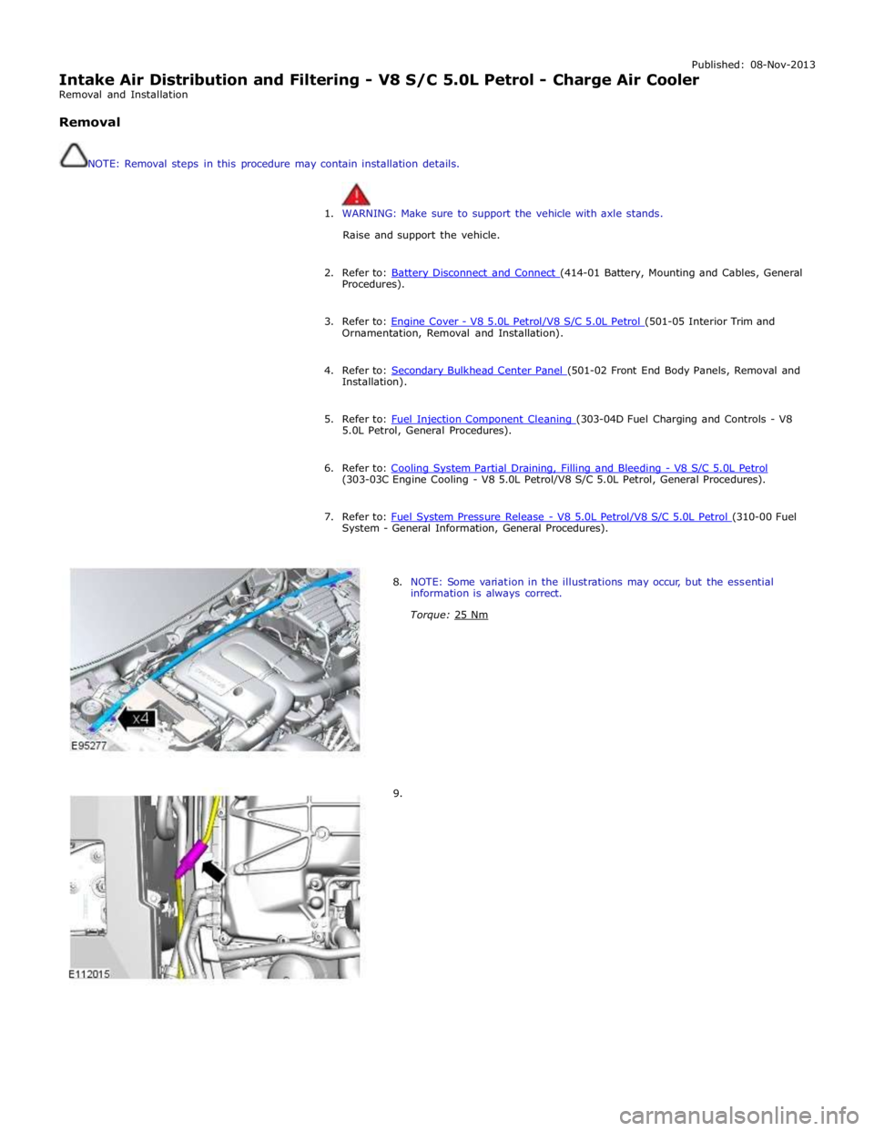
8. NOTE: Some variation in the illustrations may occur, but the essential
information is always correct.
Torque: 25 Nm
9.