Page 851 of 3039
A ISO standard cylinder numbering ISO cylinder firing order 1,2,7,3,4,5,6,8
Engine Data Location
Item Description 1 Engine data location Engine data is marked on the cylinder block at the rear of the RH cylinder bank.
CRANKSHAFT
The crankshaft is made from spheroidal graphite cast iron, which, compared with grey cast iron, has higher mechanical
strength, ductility and increased shock resistance. The undercut and rolled fillets also improve strength. Eight counter-balance The cylinders are numbered as shown below.
www.JagDocs.com
Page 853 of 3039

1 Coolant drain plug 2 Torque converter access plug 3 Drive plate 4 Rear cover 5 Main bearing cap 6 Identification mark 7 Front cover 8 Front pulley The main bearing caps are made from cast iron and are cross bolted to increase rigidity. An identification mark on the bearing
cap faces the front of the engine.
At the front of the crankshaft, a tuned torsional vibration damper is incorporated into the crankshaft front pulley. At the rear of
the crankshaft a pressed steel drive plate, with a steel starter ring gear, is installed to transfer drive from the engine to the
transmission. The reluctor ring for the CKP (crankshaft position) sensor is integrated into the perimeter of the drive plate.
The crankshaft seals are located in the front and rear covers.
PISTONS AND CONNECTING RODS
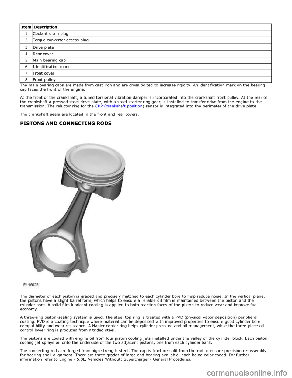
The diameter of each piston is graded and precisely matched to each cylinder bore to help reduce noise. In the vertical plane,
the pistons have a slight barrel form, which helps to ensure a reliable oil film is maintained between the piston and the
cylinder bore. A solid film lubricant coating is applied to both reaction faces of the piston to reduce wear and improve fuel
economy.
A three-ring piston-sealing system is used. The steel top ring is treated with a PVD (physical vapor deposition) peripheral
coating. PVD is a coating technique where material can be deposited with improved properties to ensure good cylinder bore
compatibility and wear resistance. A Napier center ring helps cylinder pressure and oil management, while the three-piece oil
control lower ring is produced from nitrided steel.
The pistons are cooled with engine oil from four piston cooling jets installed under the valley of the cylinder block. Each piston
cooling jet sprays oil onto the underside of the two adjacent pistons, one from each cylinder bank.
The connecting rods are forged from high strength steel. The cap is fracture-split from the rod to ensure precision re-assembly
for bearing shell alignment. There are three grades of large end bearing available, each being color coded. For further
information refer to Engine - 5.0L, Vehicles Without: Supercharger - General Procedures.
Page 858 of 3039

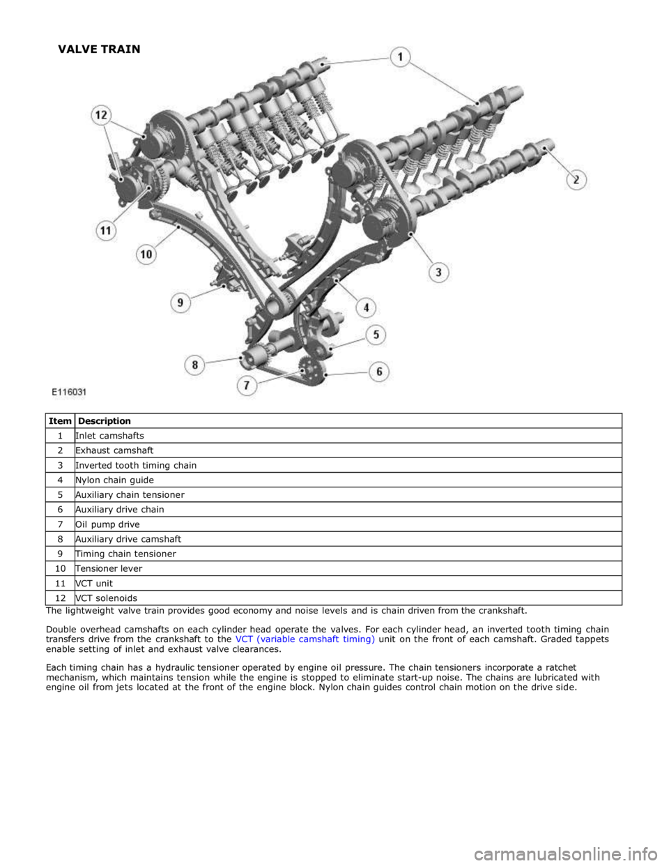
1 Inlet camshafts 2 Exhaust camshaft 3 Inverted tooth timing chain 4 Nylon chain guide 5 Auxiliary chain tensioner 6 Auxiliary drive chain 7 Oil pump drive 8 Auxiliary drive camshaft 9 Timing chain tensioner 10 Tensioner lever 11 VCT unit 12 VCT solenoids The lightweight valve train provides good economy and noise levels and is chain driven from the crankshaft.
Double overhead camshafts on each cylinder head operate the valves. For each cylinder head, an inverted tooth timing chain
transfers drive from the crankshaft to the VCT (variable camshaft timing) unit on the front of each camshaft. Graded tappets
enable setting of inlet and exhaust valve clearances.
Each timing chain has a hydraulic tensioner operated by engine oil pressure. The chain tensioners incorporate a ratchet
mechanism, which maintains tension while the engine is stopped to eliminate start-up noise. The chains are lubricated with
engine oil from jets located at the front of the engine block. Nylon chain guides control chain motion on the drive side. VALVE TRAIN
Page 860 of 3039
1 Bolt (3 off) 2 VCT unit 3 Filter 4 Camshaft 5 Inner plate 6 Housing and sprocket 7 Rotor assembly 8 Reed plate 9 Spring and lock pin 10 Spring (3 off) 11 Tip seal (3 off) 12 Spring (2 off) 13 Tip seal (2 off) 14 Spring The VCT units change the position of the camshafts in relation to the timing chains.
Page 863 of 3039
1 Advance chamber 2 Retard chamber 3 Sprocket housing 4 Rotor assembly 5 Lock pin 6 Sleeve 7 Engine oil supply from camshaft 8 Inlet check valve 9 Lock pin drain 10 Spool valve 11 Advance check valve 12 Retard check valve At engine start-up, once the engine oil pressure in the camshaft is sufficient to open the inlet check valve, engine oil flows
across the spool valve, through the advance and retard check valves and into the advance and retard chambers. During the
start cycle, the ECM signals the VCT solenoid to move the spool valve into the sleeve and connect the lock pin to inlet oil
Page 865 of 3039
valve in the null position. In the null position, the advance and retard chamber oil passages are both closed by the spool valve
and the rotor assembly is hydraulically locked to the sprocket housing. Variable Camshaft Timing Unit Schematic - Null
Page 867 of 3039
1 Oil pump outlet tube 2 Anti-drain valve 3 Oil cooler 4 Oil filter 5 Piston cooling jets 6 Timing chain lubrication jets 7 Oil evacuation tube 8 Oil pump 9 Oil temperature and level sensor 10 Oil pick-up The oil pump is attached to the underside of the windage tray. The input shaft of the oil pump is driven from the front of the
crankshaft, by the auxiliary chain, at 0.87 engine speed.
The oil pump draws oil from the sump pan through a centrally mounted pick-up pipe. The oil is pressurized and pumped
through an output tube to the cylinder block. After passing through an anti-drain valve and a plate type oil cooler, the oil is
filtered by a replaceable cartridge installed on the front of the RH cylinder head. LUBRICATION SYSTEM
Page 868 of 3039

cooling jets and the timing chain lubrication jets.
The oil returns to the oil pan under gravity. Large drain holes through the cylinder heads and cylinder block ensure the rapid
return of the oil to the sump pan. System replenishment is through the oil filler cap on the LH cylinder head cover.
An oil evacuation tube is installed to allow oil to be drawn from the sump pan. The upper end of the oil evacuation tube is
located under the oil filler cap.
An oil drain plug is installed in the RH side of the sump pan.
Oil Pump Nominal Operating Pressures
Engine Speed, rev/min Temperature, °C (°F) Pressure, bar (lbf/in2
) Idle 20 (68) 2.0 (29.0) 1500 20 (68) 6.0 (87.0) 3000 40 (104) 6.2 (90.0) 3000 110 (230) 5.0 (72.5) 3000 130 (266) 4.0 (58.0) Oil Level Monitoring
Oil level monitoring is provided by an oil level and temperature sensor that measures the oil level in the sump pan. The oil
level can be displayed in the message center of the instrument cluster.
The oil level and temperature sensor supplies the ECM with a signal containing the level and temperature of the oil in the sump pan. The oil level and temperature sensor is secured to the bottom of the sump pan with three screws and sealed with a
gasket.
The oil level and temperature sensor sends an ultrasonic pulse vertically upward and measures the time taken for the pulse to
be reflected back from the top surface of the oil. This time is compared with the time taken for an ultrasonic pulse to travel a
reference distance within the oil level and temperature sensor to determine the oil level. The oil level reading is combined with
the oil temperature reading and transmitted in a PWM signal to the ECM.
Oil Level and Temperature Sensor Specifications
Feature Details Power source Battery Voltage Level Accuracy ±2 mm (±0.08 in.) at temperatures of -30 °C (-22 °F)) and above; (±4 mm (±0.16 in.) at
temperatures below -30 °C (-22 °F)) Temperature Accuracy ±2 °C (±3.6 °F) Operating Level Range 116 to 147 mm (4.57 to 5.79 in.)