2010 JAGUAR XFR lock
[x] Cancel search: lockPage 2712 of 3039
NOTE: Any attached body parts that require accurate alignment and fitting must be incorporated in this step; for
instance bumpers, seals, headlamps, rear lamps and lock assembly components. If this is not done carefully it may
result in water leaks, wind noises and substantial follow-on work.
Make sure that edges line up with adjacent parts and check that gaps are consistent (compare left and right-hand
sides). Make sure that the shape of the vehicle is retained.
Secure the new part
NOTE: The need for subsequent follow-on work can be significantly reduced if aligning and tack-welding are carried
out with due care.
Depending on accessibility the following methods for securing are available:
- Grip pliers (set of).
- Screw clamp (set of).
- Self-tapping screws.
- Tack welds.
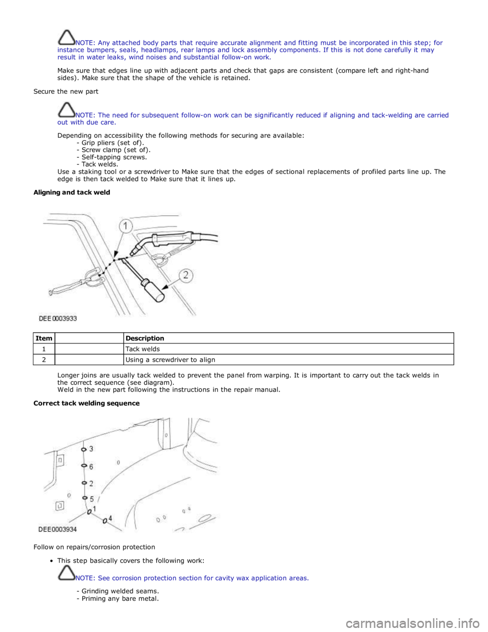
Use a staking tool or a screwdriver to Make sure that the edges of sectional replacements of profiled parts line up. The
edge is then tack welded to Make sure that it lines up.
Aligning and tack weld
Item
Description 1
Tack welds 2
Using a screwdriver to align
Longer joins are usually tack welded to prevent the panel from warping. It is important to carry out the tack welds in
the correct sequence (see diagram).
Weld in the new part following the instructions in the repair manual.
Correct tack welding sequence
Follow on repairs/corrosion protection
This step basically covers the following work:
NOTE: See corrosion protection section for cavity wax application areas.
- Grinding welded seams.
- Priming any bare metal.
Page 2714 of 3039
- Disadvantage: Scarring and hardening of the surface.
Flattening using a copper electrode.
- Small, sharp dents that face outwards can be worked on with a copper electrode.
Flattening using a flame and body files.
NOTE: When applied correctly, this method can be used with all the attached parts still in place (roof headlining,
wiring harnesses etc.).
- Small, soft dents (only slight stretching): Working at the edges of the dent in an inward spiral pattern, the dent
is heated with an oxyacetylene torch (torch size 1 - 2 mm, excess gas flame) to approx. 250° C.
- Working rapidly with a body file extracts heat from the edge area until the dent is flattened. Preferably alternate
between two files. This increases the amount of heat that can be extracted.
Safety measures
The electronic control modules (ECM) fitted to vehicles make it advisable to follow suitable precautions prior to carrying
out welding repair operations. Harsh conditions of heat and vibration may be generated during these operations which
could cause damage to the modules. In particular, it is essential to follow the appropriate precautions when
disconnecting or removing the airbag RCM.
Do not allow electronic modules or lines to come into contact with the ground connection or the welding electrode.
Seat belt anchorages are a safety critical. When making repairs in these areas, it is essential to follow design
specifications. Note that extra strength low alloy steel may be used for seat belt anchorages. Where possible, the
original production assembly should be used, complete with its seat belt anchorages, or the cut line should be so
arranged that the original seat belt anchorage is not disturbed.
All welds within 250mm (9.842) of seat belt anchorages must be carefully checked for weld quality, including spacing of
spot welds.
Remove the battery before carrying out welding work in its vicinity.
Utmost care must be taken when welding near the fuel tank or other components that contain fuel. If the tank filler
neck or a fuel line must be detached to allow access for welding work, then the fuel tank must be drained and removed.
Never weld, on components of a filled air conditioning system. The same applies if there is a risk of the air conditioning
system heating up.
Connect the ground connection of the electrical welder directly to the part that is to be welded. Make sure that there
are no electrically insulating parts between the ground connection and the welding point.
Adjacent vehicle parts and adjacent vehicles must be shielded against flying sparks and heat.
Pedestrian protection system
The pedestrian protection system is designed to mitigate injuries in a pedestrian collision with the vehicle. It does this by
utilizing a pair of pyrotechnic actuators to lift the hood away from the engine, creating a cushioned impact between the
pedestrian and the vehicle. It is essential that any repair or replacement operations do not affect the safe working of the
system.
For additional information, refer to: Pedestrian Protection System (501-20C Pedestrian Protection System, Description and Operation).
Resistance spot welding
Where resistance spot welds have been used in production, they must be reproduced with new spot welds in replacement
where possible. All such reproduction spot welds should be spaced 25 to 30mm apart.
Setting up the equipment and co-ordinating the welding parameters.
Equipment:
- Follow the equipment manufacturer's instructions for the equipment settings.
- Select the correct electrode arms (as short as possible).
- Align the electrode arms and tips exactly.
- Electrode tips should be convex (rough shaping with a file, fine shaping with a sanding block).
Body:
- Make sure that the flanges to be joined lie perfectly flat to one another.
- Prepare a bare metal joint surface (inside and outside).
Notes on technique/method:
- Carry out a test weld on a sample piece of the material coated in welding paste.
- If any metal parts are located between the electrode arms then there will be a loss of induction and therefore
power (adjust current setting).
- The power needs to be adjusted for high-strength low alloy steel.
- Repeated welding on old welding points often leads to poor quality welds.
- Keep the electrode tips as near as possible to an angle of 90° to the contact surface.
- Keep the pressure on the electrodes for a short period after finishing the weld.
- The electrodes work best if their shape is convex. Clean the contact surface of the electrodes regularly.
Resistance spot welding panels where the total thickness is 3 mm or more
For all repairs to modern Jaguar vehicles, spot-welding equipment should be suitable for reliable welding of zinc-plated,
high-strength and high-tensile steels in three or more layers, up to 5 mm total thickness. If these requirements are not
fulfilled, plug welding must be used for safety reasons. The electrical specifications (current, resistance, heat) of the
spot-welding equipment have different validity, depending upon the type of equipment. Therefore, it is essential that the
manufacturer's instructions are observed with regard to the actual welding performance.
www.JagDocs.com
Page 2723 of 3039

Terotex HV 200 extra spray - 1L can Teroson 176.48 Terotex HV 200 extra spray - 10L tin Teroson 179.40A Terotex HV 200 extra spray - 60L barrel Teroson 170.96J Terotex HV 400 1L can Teroson 169.65Q Terotex HV 400 10L tin Teroson 169.76C Terotex HV 400 60L barrel Teroson 169.85M Teroson cavity spray 500ml aerosol Teroson 155.71A Underbody Wax - - Terotex wax black 1L can Teroson 114.59F Protective wax Teroson 122.73Q Underbody Coating - - Bodyguard stonechip coating (textured) can - black 3M 08868 Bodyguard stonechip coating (textured) can - white 3M 08878 Bodyguard stonechip coating (textured) can - grey 3M 08879 Bodyguard stonechip coating (flat) can - black 3M 08158 Bodyguard stonechip coating (flat) can - grey 3M 08159 Anti chip coating smooth - grey 3M 08886 Terotex record black 1L can Teroson 122.48N Terotex record light 1L can Teroson 165.53S Terotex anti chip compound light (UBC) 1L can Teroson 191.08V Terotex anti chip compound black (UBC) 1L can Teroson 191.32V Trim Adhesive - - Auto adhesive - aerosol - clear (trim) 3M 08080 Auto adhesive - brushable - clear (trim) 3M 08150 Contact adhesive - aerosol - amber 3M 08090 Corrosion Protection - - Zinc spray 3M 09113 Zinc spray Teroson 158.18T Anti Corrosive Agent - - Terotex HV 350 1L can Teroson 141.78L Terotex HV 350 10L can Teroson 160.02T Terotex HV 350 60L barrel Teroson 160.01S Sound Deadening - - Sound deadening sheets 3M 08840 Terodem SP 100 alu Teroson 190.33 Terodem SP 200 Teroson 190.55M Terodem SP 300 50 x 50 Teroson 145.28R Terodem SP 300 100 x 50 Teroson 134.29X Flexible Part Repair - - Flexible part repair material (FPRM) 3M 05900 Adhesives / Thread Locking - - Lock N Seal 243 thread locking Loctite 13701 Lock N Seal 243 thread locking Loctite 14131 Lock N Seal 243 thread locking Loctite 25684 Stud N Bearing fit 271 Loctite 13704 Stud N Bearing fit 271 Loctite 14130 Stud N Bearing fit 271 Loctite 25685 Pipe sealant 577 Loctite 16604 Pipe sealant 577 Loctite 25689 Pipe sealant 55 Loctite 31899 Gasket - - Multi gasket Loctite 25688 Silicone copper Loctite 19245 Silicone copper Loctite 82046 Silicone 596 black Loctite 19242 Silicone 596 black Loctite 59875 3020 gasket adhesive Loctite 31458 NVH Baffle - - Sikabaffle 278 SIKA Approved Service Material Supplier - Contact Details
3M
3M United Kingdom PLC
3M Centre
Cain Road
Bracknell
Berkshire
RG12 8HT
Telephone (01344) 858000
www.3m.com
Page 2726 of 3039
metal surfaces are bolted together always interpose a suitable interface material such as weldable zinc rich primer, extruded
strip, or zinc tape.
Steam Cleaning
Due to the high pressure/temperature generated by steam cleaning equipment, there is a risk that certain adhesives and
corrosion prevention material may become softened or liquified.
Take care not to allow the steam jet to dwell on one area, and keep the nozzle at least 300mm from the panel surface.
CAUTION: Do not remove wax or lacquer from underbody areas during repairs.
Inspection During Maintenance Servicing
It is a requirement of the corrosion warranty that the vehicle is inspected for corrosion by a Jaguar Authorised Repairer during a
routine service, to ensure that the factory-applied protection remains effective.
Rectify any bodywork damage or evidence of corrosion found during inspection as soon as is practicable, both to minimise the
extent of the damage and to ensure the long term effectiveness of the factory-applied corrosion prevention treatment.
Underbody Protection Repairs
Whenever body repairs have been carried out, ensure that full sealing and corrosion protection treatments are reinstated. This
applies both to the damaged areas and also to areas where protection has been indirectly impaired, as a result either of
accident damage or repair operations.
Remove corrosion protection from the damaged areas before straightening or panel beating. This applies in particular to panels
coated with wax, PVC underbody sealer, sound deadening pads etc.
CAUTION: Do not use oxy-acetylene to remove corrosion prevention material. Large volumes of fumes and gases are
liberated by these materials when they burn.
The most common method of removal is by means of a hot air blower with an integral scraper. High temperatures can be
generated with this equipment which may cause fumes. Take care during its use.
Structural Adhesive
CAUTION: When separating a joint with metal to metal adhesive, it is important to avoid distortion. Heat gradually until
the bond weakens sufficiently to permit panel separation - do not apply excessive heat.
NOTE: When spot welding through metal to metal adhesive, take particular care to adjust the equipment setting to
ensure a suitable weld.
Metal to metal adhesive is applied to critical joint areas during factory assembly. The material used is a high temperature,
heat cured, nitrile phenolic which serves to bond two metal surfaces and also to seal the joint against ingress of dust,
moisture and fumes. This material is not suitable for service use and, during repair, should be substituted by an approved
structural adhesive. For panel specific information and to identify the areas of structural adhesive application in repair, refer to
the relevant sheet metal removal and installation procedure.
Expanding Foam Acoustic Seals
Expanding foam acoustic seals are used in various closed-sections of the body to improve vehicle refinement. The seals are
installed during the vehicle body manufacture and expand during the paint process up to ten times original size, thus locking
them into position. They are located such that they prevent noise accentuation along a section and reflect air borne noise
away from the cabin.
The seals have spilt functionality depending on location. The seals located at the base of the body pillars have a primary
function of preventing water ingress when wading. Their secondary function is to prevent noise and dust ingress.
The seal around the fuel filler has a primary function of preventing both fuel and water ingress. With a secondary function of
preventing noise and dust ingress.
The remaining seals primary function is to prevent noise accentuation along a section and reflect air borne noise away from the
cabin.
Another advantage of the seals is that they marginally increase the overall stiffness of the body and its structural performance
in case of a crash.
The seals are manufactured from an expandible polymer.
Replacing Expanding Foam Acoustic Seals
As paint oven temperatures used in a repair workshop are significantly lower than those that are used during manufacture of
the vehicle, (the temperatures are not sufficient to expand the foam), a different process is required to replicate the foam in
repair.
Page 2735 of 3039
Side windows
In the case of side windows, the same problems can arise as for a windscreen. The same corrective actions must therefore be
used.
Door seal
Diagnosis:
- Water ingress in the lower part of the interior door trim or in the rocker panel area.
Cause:
- The water shield fitted behind the interior door trim exists to drain off water that has entered the door via the
drainage holes, either downwards or outwards. If the water shield seal is damaged or has been fitted incorrectly,
then water can get into the passenger compartment.
- In addition to this, the drainage holes can become clogged with leaves, dirt or excess cavity protection agents.
Water gathers in the door and ingresses into the passenger compartment.
- Check water shield for damage or correct fitting.
- If the water shield needs to be re-bonded, then approved seam sealer should be used.
- Before the water shield is installed, the drainage holes must be checked for unhindered flow.
Door seals
Diagnosis:
- Ingress of water into the rocker panel area
Cause:
- Insufficient clamping load between seal and door.
Corrective action:
NOTE: When adjusting the clamping load, the profile alignment of the relevant components must always be taken
into consideration.
NOTE: Do not realign the flange too far in the direction of the door, as this can reduce the bearing surface of the
seal to the door.
- Check clamping load:
- The easiest way to check the clamping load of a seal to the respective bearing surface is by means of a paper
strip test. This consists of trapping strips of paper at various points between the door and the seal, and fully
closing the door. If it is possible to pull out the paper with no great resistance, then the clamping load is too
low.
- Adjust the clamping load:
- The clamping load is normally adjusted using the striker. When doing so, the edge alignment from the door to
the side panel, or from the front door to the rear door must be taken into account.
- Another setting method is to realign the panel flange for the seal mounting. The clamping load is increased by
moving the flange towards the door.
- Check the bearing surface:
- Apply chalk evenly to the surface of the seal. Evenly coat the bearing surface of the door with Vaseline.
- Close the door fully, the lock must engage. Open the door. The imprint of the chalk (bearing surface) can be
identified in the film of Vaseline.
- The bearing surface should be at least 5mm across at all points.
Other causes:
- The door seal must completely seal the door where it meets the bodywork.
- Water can ingress directly or indirectly into the interior of the vehicle if the seal is damaged at any point.
Corrective action:
- A damaged or worn door seal must always be renewed in full.
- When renewing the seal, the following must be taken into account:
- Always fit the seal first in the area of the narrow radii (corner points).
- Next, secure the seal to the flange evenly by tapping lightly with a rubber hammer. The installed seal must not
be kinked at any point.
NOTE: The prescribed length of a seal must not be shortened.
Other cause:
- The door seal is attached to the welded flange all the way round. If this welded flange is uneven or damaged at
any point (usually in areas with small radii) then this point could be subject to leaks.
- A stretched seal carrier can also cause a leak.
- In both cases, water gets into the vehicle interior under the seal carrier.
Corrective action:
- Align the deformed welded flange using a hammer and anvil block, prevent and, if necessary, repair any paint
damage.
Sliding roof/tilting roof
Diagnosis:
- Ingress of water at sliding roof aperture
Cause:
- The sliding roof/tilting roof is installed in a water trap. The water drains off via the water trap, water drain holes
and drain hoses. The drain hoses lead downwards on both sides via the A-pillar and B-pillar.
- The drain holes or drain hoses can become clogged with leaves, dirt, underbody protection and so on.
Corrective action:
Page 2736 of 3039
NOTE: In the case of a sliding or tilting roof, the external rubber seal and the lock actuator or latch mechanism
must be checked first of all.
- Check the water trap for leaks.
- Check the drain hoses for leaks and for correct connection to the water trap.
- Check the drainage system for unhindered flow, and blow out with compressed air if necessary.
- Check the external seal and the correct adjustment of the sliding roof.
Liftgate
Diagnosis:
- Ingress of water into rear headlining area and luggage area.
Cause:
- The leak problems of the tailgate and liftgate correspond to those of the doors.
- In addition to this, the area to be sealed is much bigger. The routing holes for cables and hoses must also be
sealed.
- The rubber grommets for the routing holes must be checked for damage and correct seating (fully unhooked).
- The mounting points of the liftgate hinges may leak.
Corrective action:
- Check the rubber grommets and renew if necessary.
- Check the hinge mounting points, and re-seal with sealing compound if necessary.
Forced air extraction
Diagnosis:
- Ingress of water into side luggage compartment area
Cause:
- The forced air extraction for the vehicle interior is located in the quarter panel lower extension.
- The rubber flap of the forced air extraction must be able to move freely.
Corrective action:
- Remove the forced air extraction.
- Check the seal area between the bodywork and housing, as well as the rubber flap.
- Renew seal if necessary.
Rear window
Diagnosis:
- Ingress of water into the luggage compartment area
Cause:
- Rear window leaking.
- Check for leak in the same way as for leaking windscreen.
Page 2881 of 3039
(100-00 General Information, Description and Operation) /
Body Repairs (501-25A Body Repairs - General Information, Description and Operation) /
Corrosion Protection (501-25B Body Repairs - Corrosion Protection, Description and Operation) /
Body and Frame (501-26 Body Repairs - Vehicle Specific Information and Tolerance Checks, Description and Operation).
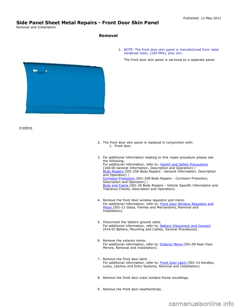
4. Remove the front door window regulator and motor.
For additional information, refer to: Front Door Window Regulator and Motor (501-11 Glass, Frames and Mechanisms, Removal and Installation).
5. Disconnect the battery ground cable.
For additional information, refer to: Battery Disconnect and Connect (414-01 Battery, Mounting and Cables, General Procedures).
6. Remove the exterior mirror.
For additional information, refer to: Exterior Mirror (501-09 Rear View Mirrors, Removal and Installation).
7. Remove the front door latch.
For additional information, refer to: Front Door Latch (501-14 Handles, Locks, Latches and Entry Systems, Removal and Installation).
8. Remove the front door outer window frame mouldings.
9. Remove the front door weatherstrips.
Page 2887 of 3039
(100-00 General Information, Description and Operation) /
Body Repairs (501-25A Body Repairs - General Information, Description and Operation) /
Corrosion Protection (501-25B Body Repairs - Corrosion Protection, Description and Operation) /
Body and Frame (501-26 Body Repairs - Vehicle Specific Information and Tolerance Checks, Description and Operation).
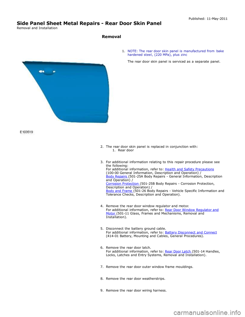
4. Remove the rear door window regulator and motor.
For additional information, refer to: Rear Door Window Regulator and Motor (501-11 Glass, Frames and Mechanisms, Removal and Installation).
5. Disconnect the battery ground cable.
For additional information, refer to: Battery Disconnect and Connect (414-01 Battery, Mounting and Cables, General Procedures).
6. Remove the rear door latch.
For additional information, refer to: Rear Door Latch (501-14 Handles, Locks, Latches and Entry Systems, Removal and Installation).
7. Remove the rear door outer window frame mouldings.
8. Remove the rear door weatherstrips.
9. Remove the rear door wiring harness.