2010 JAGUAR XFR lock
[x] Cancel search: lockPage 1181 of 3039
to deliver the correct mass of fuel to the combustion chambers.
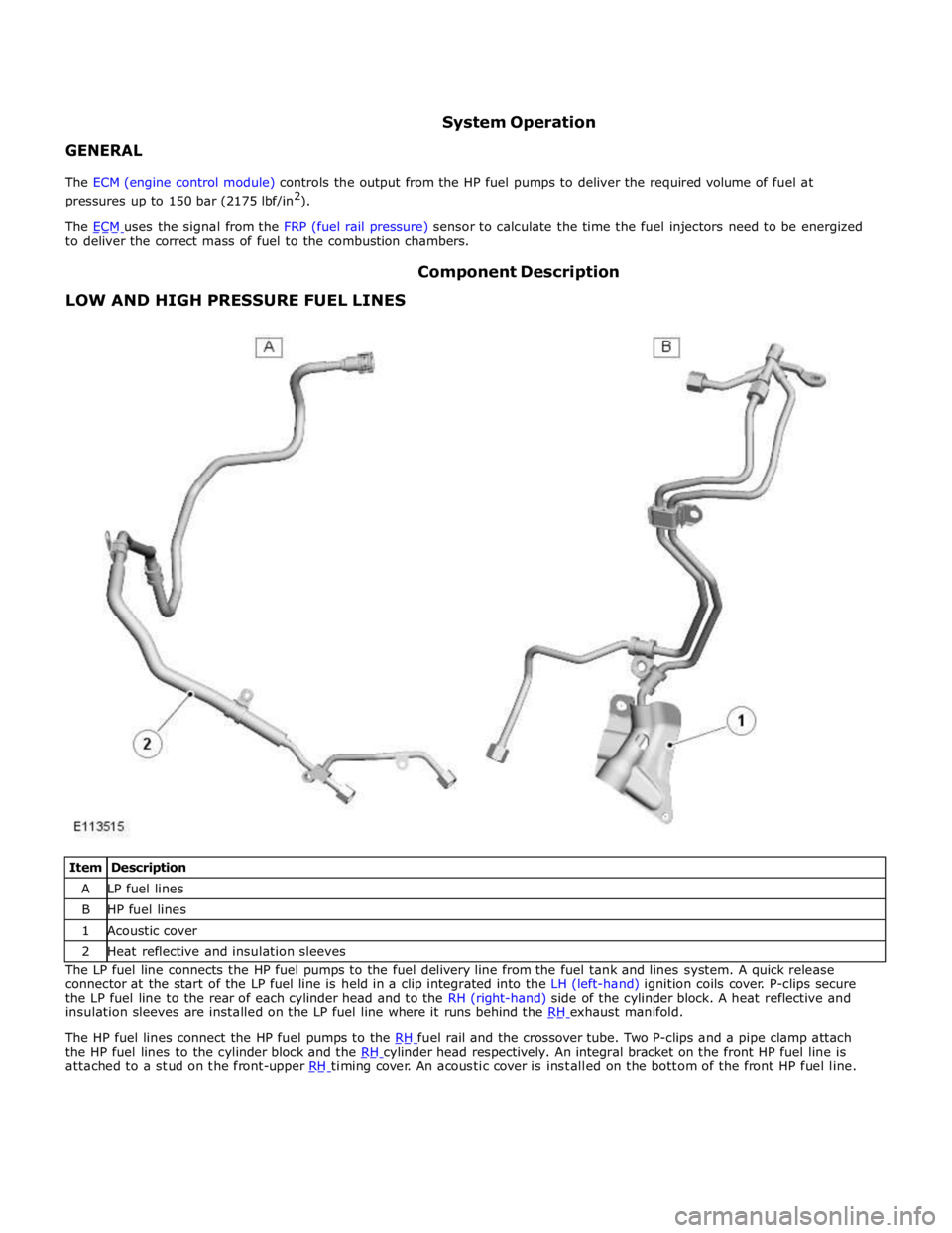
LOW AND HIGH PRESSURE FUEL LINES Component Description
Item Description A LP fuel lines B HP fuel lines 1 Acoustic cover 2 Heat reflective and insulation sleeves The LP fuel line connects the HP fuel pumps to the fuel delivery line from the fuel tank and lines system. A quick release
connector at the start of the LP fuel line is held in a clip integrated into the LH (left-hand) ignition coils cover. P-clips secure
the LP fuel line to the rear of each cylinder head and to the RH (right-hand) side of the cylinder block. A heat reflective and
insulation sleeves are installed on the LP fuel line where it runs behind the RH exhaust manifold.
The HP fuel lines connect the HP fuel pumps to the RH fuel rail and the crossover tube. Two P-clips and a pipe clamp attach the HP fuel lines to the cylinder block and the RH cylinder head respectively. An integral bracket on the front HP fuel line is attached to a stud on the front-upper RH timing cover. An acoustic cover is installed on the bottom of the front HP fuel line.
Page 1185 of 3039
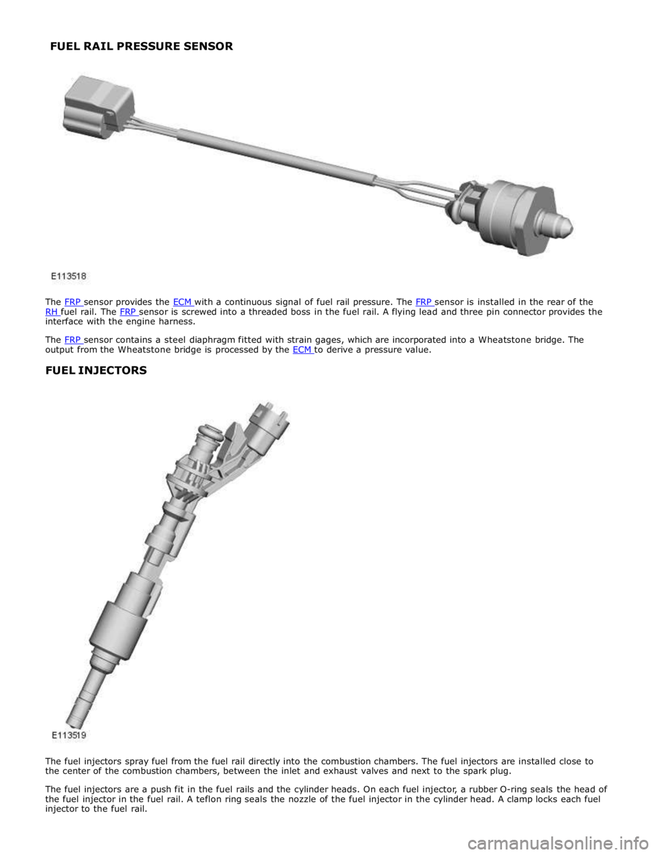
RH fuel rail. The FRP sensor is screwed into a threaded boss in the fuel rail. A flying lead and three pin connector provides the interface with the engine harness.
The FRP sensor contains a steel diaphragm fitted with strain gages, which are incorporated into a Wheatstone bridge. The output from the Wheatstone bridge is processed by the ECM to derive a pressure value.
FUEL INJECTORS
The fuel injectors spray fuel from the fuel rail directly into the combustion chambers. The fuel injectors are installed close to
the center of the combustion chambers, between the inlet and exhaust valves and next to the spark plug.
The fuel injectors are a push fit in the fuel rails and the cylinder heads. On each fuel injector, a rubber O-ring seals the head of
the fuel injector in the fuel rail. A teflon ring seals the nozzle of the fuel injector in the cylinder head. A clamp locks each fuel
injector to the fuel rail. FUEL RAIL PRESSURE SENSOR
Page 1188 of 3039

Symptom Possible Causes Action Purge valve
Difficult hot start
Injector leak
Electronic engine control
Purge valve
Fuel pump
Ignition system
EGR valve stuck open Check for injector leak, install new injector as required.
Check for electronic engine controls, evaporative emissions,
fuel system, ignition system and engine emission system
related DTCs and refer to the relevant DTC Index Difficult to start after hot
soak (vehicle standing,
engine off, after engine has
reached operating
temperature)
Injector leak
Electronic engine control
Purge valve
Fuel pump
Ignition system
EGR valve stuck open Check for injector leak, install new injector as required.
Check for electronic engine controls, evaporative emissions,
fuel system, ignition system and engine emission system
related DTCs and refer to the relevant DTC Index Engine stalls soon after start
Breather system
disconnected/restricted
ECM relay
Electronic engine control
Ignition system
Air intake system restricted
Air leakage
Fuel lines Ensure the engine breather system is free from restriction
and is correctly installed. Check for electronic engine
control, ignition system and fuel system related DTCs and
refer to the relevant DTC Index. Check for blockage in air
filter element and air intake system. Check for air leakage
in air intake system Engine hesitates/poor
acceleration
Fuel pressure, fuel pump,
fuel lines
Injector leak
Air leakage
Electronic engine control
Throttle motor
Restricted accelerator pedal
travel (carpet, etc)
Ignition system
EGR valve stuck open
Transmission malfunction Check for fuel system related DTCs and refer to the
relevant DTC Index. Check for injector leak, install new
injector as required. Check for air leakage in air intake
system. Ensure accelerator pedal is free from restriction.
Check for electronic engine controls, ignition, engine
emission system and transmission related DTCs and refer
to the relevant DTC Index Engine backfires
Fuel pump/lines
Air leakage
Electronic engine controls
Ignition system
Sticking variable camshaft
timing (VCT) hub Check for fuel system failures. Check for air leakage in
intake air system. Check for electronic engine controls,
ignition system and VCT system related DTCs and refer to
the relevant DTC Index Engine surges
Fuel pump/lines
Electronic engine controls
Throttle motor
Ignition system Check for fuel system failures. Check for electronic engine
controls, throttle system and ignition system related DTCs
and refer to the relevant DTC Index Engine detonates/knocks
Fuel pump/lines
Air leakage
Electronic engine controls
Sticking VCT hub Check for fuel system failures. Check for air leakage in
intake air system. Check for electronic engine controls and
VCT system related DTCs and refer to the relevant DTC
Index No throttle response
Electronic engine controls
Throttle motor Check for electronic engine controls and throttle system
related DTCs and refer to the relevant DTC Index Poor throttle response
Breather system
disconnected/restricted
Electronic engine control
Transmission malfunction
Traction control event Air
leakage Ensure the engine breather system is free from restriction
and is correctly installed. Check for electronic engine
controls, transmission and traction control related DTCs and
refer to the related DTC Index. Check for air leakage in
intake air system DTC Index
For a list of Diagnostic Trouble Codes (DTCs) that could be logged in the Engine Control Module (ECM), please refer to Section
303-14.
REFER to: Electronic Engine Controls (303-14C Electronic Engine Controls - V8 5.0L Petrol, Diagnosis and Testing) / Electronic Engine Controls (303-14D Electronic Engine Controls - V8 S/C 5.0L Petrol, Diagnosis and Testing).
Page 1189 of 3039
Published: 11-May-2011
Fuel Charging and Controls - V8 S/C 5.0L Petrol - Fuel Injection Component Cleaning
General Procedures
General Equipment
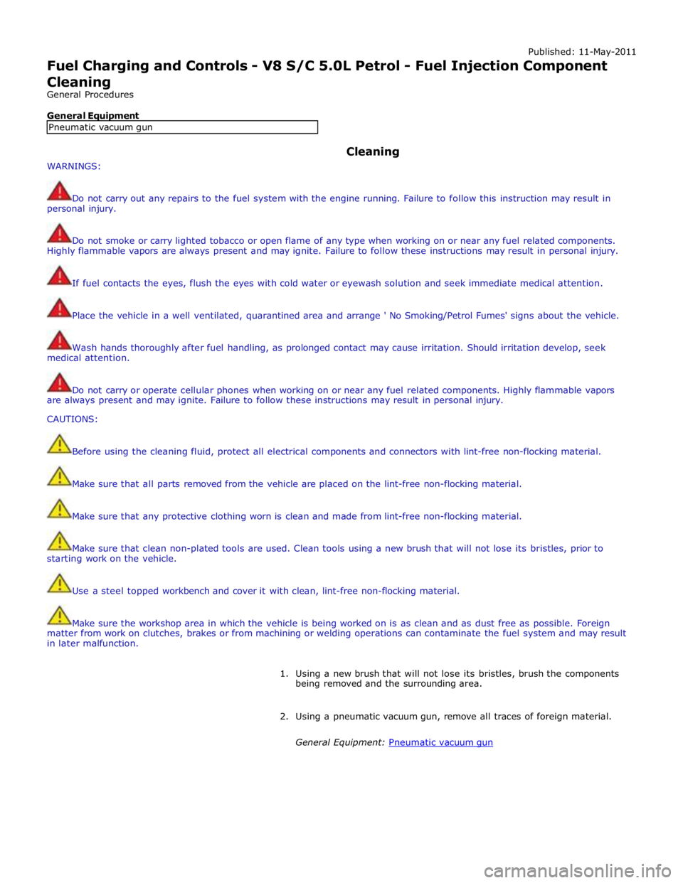
WARNINGS: Cleaning
Do not carry out any repairs to the fuel system with the engine running. Failure to follow this instruction may result in
personal injury.
Do not smoke or carry lighted tobacco or open flame of any type when working on or near any fuel related components.
Highly flammable vapors are always present and may ignite. Failure to follow these instructions may result in personal injury.
If fuel contacts the eyes, flush the eyes with cold water or eyewash solution and seek immediate medical attention.
Place the vehicle in a well ventilated, quarantined area and arrange ' No Smoking/Petrol Fumes' signs about the vehicle.
Wash hands thoroughly after fuel handling, as prolonged contact may cause irritation. Should irritation develop, seek
medical attention.
Do not carry or operate cellular phones when working on or near any fuel related components. Highly flammable vapors
are always present and may ignite. Failure to follow these instructions may result in personal injury.
CAUTIONS:
Before using the cleaning fluid, protect all electrical components and connectors with lint-free non-flocking material.
Make sure that all parts removed from the vehicle are placed on the lint-free non-flocking material.
Make sure that any protective clothing worn is clean and made from lint-free non-flocking material.
Make sure that clean non-plated tools are used. Clean tools using a new brush that will not lose its bristles, prior to
starting work on the vehicle.
Use a steel topped workbench and cover it with clean, lint-free non-flocking material.
Make sure the workshop area in which the vehicle is being worked on is as clean and as dust free as possible. Foreign
matter from work on clutches, brakes or from machining or welding operations can contaminate the fuel system and may result
in later malfunction.
1. Using a new brush that will not lose its bristles, brush the components
being removed and the surrounding area.
2. Using a pneumatic vacuum gun, remove all traces of foreign material.
General Equipment: Pneumatic vacuum gun Pneumatic vacuum gun
Page 1266 of 3039
Symptom - Message Displayed Symptom - Possible Cause Action NOTE: Back up start - 10MY onwards
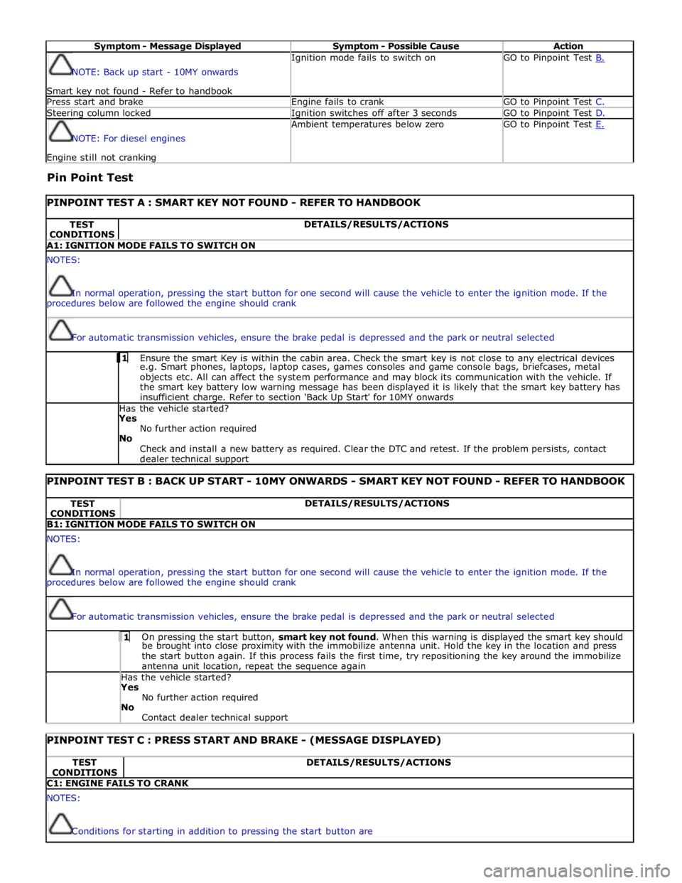
Smart key not found - Refer to handbook Ignition mode fails to switch on GO to Pinpoint Test B. Press start and brake Engine fails to crank GO to Pinpoint Test C. Steering column locked Ignition switches off after 3 seconds GO to Pinpoint Test D. NOTE: For diesel engines Engine still not cranking Ambient temperatures below zero GO to Pinpoint Test E.
Pin Point Test
PINPOINT TEST A : SMART KEY NOT FOUND - REFER TO HANDBOOK TEST
CONDITIONS DETAILS/RESULTS/ACTIONS A1: IGNITION MODE FAILS TO SWITCH ON NOTES:
In normal operation, pressing the start button for one second will cause the vehicle to enter the ignition mode. If the
procedures below are followed the engine should crank
For automatic transmission vehicles, ensure the brake pedal is depressed and the park or neutral selected 1 Ensure the smart Key is within the cabin area. Check the smart key is not close to any electrical devices e.g. Smart phones, laptops, laptop cases, games consoles and game console bags, briefcases, metal
objects etc. All can affect the system performance and may block its communication with the vehicle. If
the smart key battery low warning message has been displayed it is likely that the smart key battery has
insufficient charge. Refer to section 'Back Up Start' for 10MY onwards Has the vehicle started? Yes
No further action required
No
Check and install a new battery as required. Clear the DTC and retest. If the problem persists, contact
dealer technical support
PINPOINT TEST B : BACK UP START - 10MY ONWARDS - SMART KEY NOT FOUND - REFER TO HANDBOOK TEST
CONDITIONS DETAILS/RESULTS/ACTIONS B1: IGNITION MODE FAILS TO SWITCH ON NOTES:
In normal operation, pressing the start button for one second will cause the vehicle to enter the ignition mode. If the
procedures below are followed the engine should crank
For automatic transmission vehicles, ensure the brake pedal is depressed and the park or neutral selected 1 On pressing the start button, smart key not found. When this warning is displayed the smart key should be brought into close proximity with the immobilize antenna unit. Hold the key in the location and press
the start button again. If this process fails the first time, try repositioning the key around the immobilize
antenna unit location, repeat the sequence again Has the vehicle started? Yes
No further action required
No
Contact dealer technical support
PINPOINT TEST C : PRESS START AND BRAKE - (MESSAGE DISPLAYED) TEST
CONDITIONS DETAILS/RESULTS/ACTIONS C1: ENGINE FAILS TO CRANK NOTES:
Conditions for starting in addition to pressing the start button are
Page 1267 of 3039
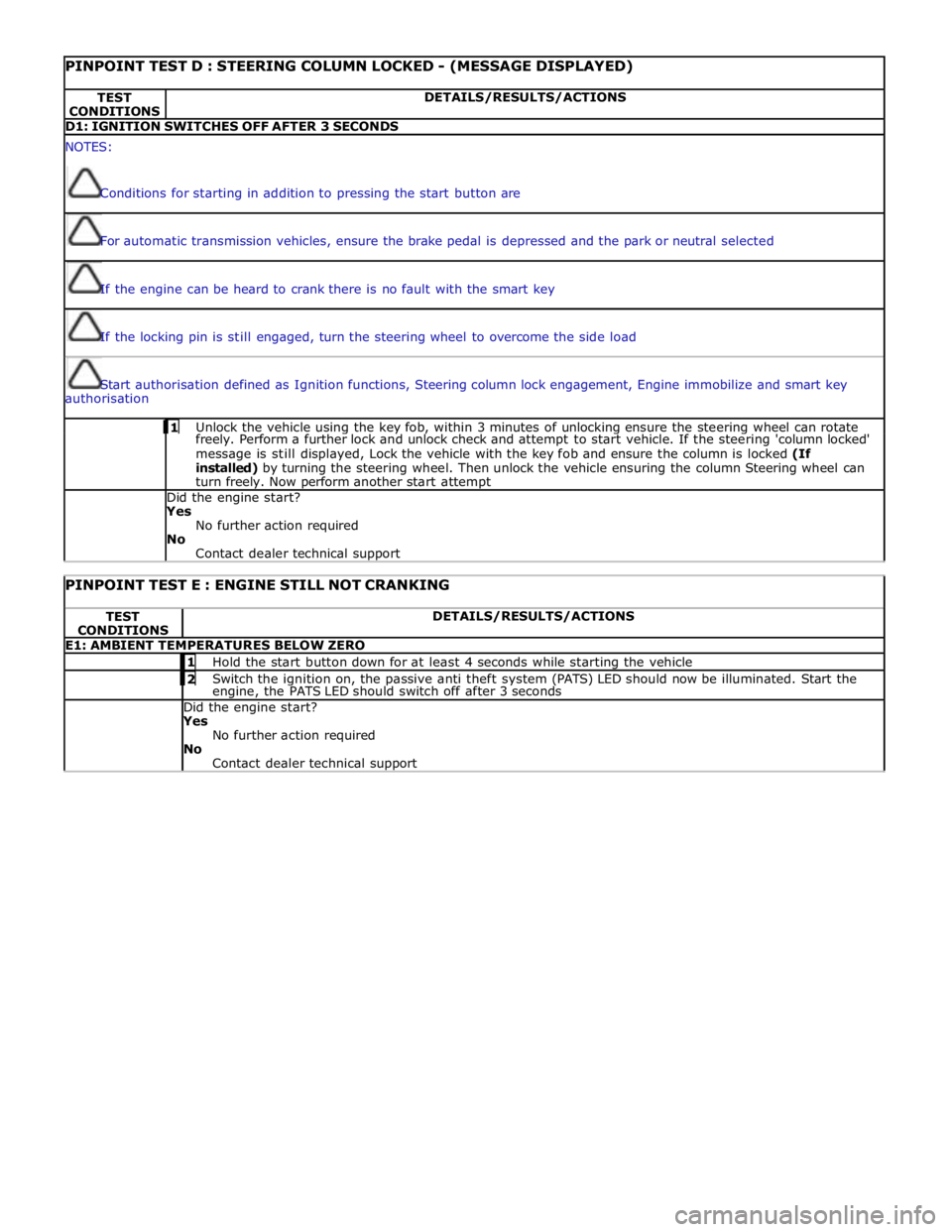
PINPOINT TEST D : STEERING COLUMN LOCKED - (MESSAGE DISPLAYED) TEST
CONDITIONS DETAILS/RESULTS/ACTIONS D1: IGNITION SWITCHES OFF AFTER 3 SECONDS NOTES:
Conditions for starting in addition to pressing the start button are
For automatic transmission vehicles, ensure the brake pedal is depressed and the park or neutral selected
If the engine can be heard to crank there is no fault with the smart key
If the locking pin is still engaged, turn the steering wheel to overcome the side load
Start authorisation defined as Ignition functions, Steering column lock engagement, Engine immobilize and smart key
authorisation 1 Unlock the vehicle using the key fob, within 3 minutes of unlocking ensure the steering wheel can rotate freely. Perform a further lock and unlock check and attempt to start vehicle. If the steering 'column locked'
message is still displayed, Lock the vehicle with the key fob and ensure the column is locked (If
installed) by turning the steering wheel. Then unlock the vehicle ensuring the column Steering wheel can
turn freely. Now perform another start attempt Did the engine start?
Yes
No further action required
No
Contact dealer technical support
PINPOINT TEST E : ENGINE STILL NOT CRANKING TEST
CONDITIONS DETAILS/RESULTS/ACTIONS E1: AMBIENT TEMPERATURES BELOW ZERO 1 Hold the start button down for at least 4 seconds while starting the vehicle 2 Switch the ignition on, the passive anti theft system (PATS) LED should now be illuminated. Start the engine, the PATS LED should switch off after 3 seconds Did the engine start? Yes
No further action required
No
Contact dealer technical support
Page 1277 of 3039

Symptom Possible Causes Action Difficult hot start
Injector leak
Electronic engine control
Purge valve
Fuel pump
Ignition system
EGR valve stuck open Check for injector leak, install new injector as required.
Check for electronic engine controls, evaporative emissions,
fuel system, ignition system and engine emission system
related DTCs and refer to the relevant DTC Index Difficult to start after hot
soak (vehicle standing,
engine off, after engine has
reached operating
temperature)
Injector leak
Electronic engine control
Purge valve
Fuel pump
Ignition system
EGR valve stuck open Check for injector leak, install new injector as required.
Check for electronic engine controls, evaporative emissions,
fuel system, ignition system and engine emission system
related DTCs and refer to the relevant DTC Index Engine stalls soon after start
Breather system
disconnected/restricted
ECM relay
Electronic engine control
Ignition system
Air intake system restricted
Air leakage
Fuel lines Ensure the engine breather system is free from restriction
and is correctly installed. Check for electronic engine
control, ignition system and fuel system related DTCs and
refer to the relevant DTC Index. Check for blockage in air
filter element and air intake system. Check for air leakage
in air intake system Engine hesitates/poor
acceleration
Fuel pressure, fuel pump,
fuel lines
Injector leak
Air leakage
Electronic engine control
Throttle motor
Restricted accelerator pedal
travel (carpet, etc)
Ignition system
EGR valve stuck open
Transmission malfunction Check for fuel system related DTCs and refer to the
relevant DTC Index. Check for injector leak, install new
injector as required. Check for air leakage in air intake
system. Ensure accelerator pedal is free from restriction.
Check for electronic engine controls, ignition, engine
emission system and transmission related DTCs and refer
to the relevant DTC Index Engine backfires
Fuel pump/lines
Air leakage
Electronic engine controls
Ignition system
Sticking variable camshaft
timing (VCT) hub Check for fuel system failures. Check for air leakage in
intake air system. Check for electronic engine controls,
ignition system and VCT system related DTCs and refer to
the relevant DTC Index Engine surges
Fuel pump/lines
Electronic engine controls
Throttle motor
Ignition system Check for fuel system failures. Check for electronic engine
controls, throttle system and ignition system related DTCs
and refer to the relevant DTC Index Engine detonates/knocks
Fuel pump/lines
Air leakage
Electronic engine controls
Sticking VCT hub Check for fuel system failures. Check for air leakage in
intake air system. Check for electronic engine controls and
VCT system related DTCs and refer to the relevant DTC
Index No throttle response
Electronic engine controls
Throttle motor Check for electronic engine controls and throttle system
related DTCs and refer to the relevant DTC Index Poor throttle response
Breather system
disconnected/restricted
Electronic engine control
Transmission malfunction
Traction control event Air
leakage Ensure the engine breather system is free from restriction
and is correctly installed. Check for electronic engine
controls, transmission and traction control related DTCs and
refer to the related DTC Index. Check for air leakage in
intake air system DTC Index
For a list of Diagnostic Trouble Codes (DTCs) that could be logged in the Engine Control Module (ECM), please refer to Section
303-14. REFER to:
Electronic Engine Controls (303-14C Electronic Engine Controls - V8 5.0L Petrol, Diagnosis and Testing), Electronic Engine Controls (303-14D Electronic Engine Controls - V8 S/C 5.0L Petrol, Diagnosis and Testing).
Page 1290 of 3039
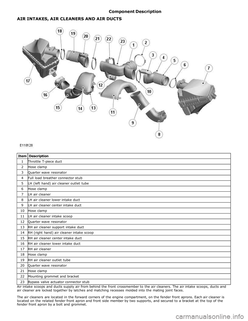
1 Throttle T-piece duct 2 Hose clamp 3 Quarter wave resonator 4 Full load breather connector stub 5 LH (left hand) air cleaner outlet tube 6 Hose clamp 7 LH air cleaner 8 LH air cleaner lower intake duct 9 LH air cleaner center intake duct 10 Hose clamp 11 LH air cleaner intake scoop 12 Quarter wave resonator 13 RH air cleaner support intake duct 14 RH (right hand) air cleaner intake scoop 15 RH air cleaner center intake duct 16 RH air cleaner lower intake duct 17 RH air cleaner 18 Hose clamp 19 RH air cleaner outlet tube 20 Quarter wave resonator 21 Hose clamp 22 Mounting grommet and bracket 23 Bypass valve actuator connector stub Air intake scoops and ducts supply air from behind the front crossmember to the air cleaners. The air intake scoops, ducts and
air cleaner are locked together by latches and matching recesses molded into the mating joint faces.
The air cleaners are located in the forward corners of the engine compartment, on the fender front aprons. Each air cleaner is
located on the related fender front apron and front side member by two supports, and secured to a bracket at the top of the
fender front apron by a bolt and grommet. AIR INTAKES, AIR CLEANERS AND AIR DUCTS