2010 JAGUAR XFR lock
[x] Cancel search: lockPage 1292 of 3039
9 Support 10 Inlet connection 11 Outlet connection 12 MAFT sensor The outlet tubes and T-piece duct direct the air from the air cleaners to the electric throttle. Hose clamps connect the outlet
tubes and T-piece duct together, and to the air cleaners and the electric throttle. A grommet and bracket attached the T-piece
duct to a bracket on the RH cylinder head. The two outlet tubes and the T-piece duct each incorporate a quarter wave resonator to reduce air induction noise.
The LH (left-hand) outlet tube incorporates a connector stub for the engine full load breather pipe.
The T-piece duct incorporates a connector stub for the vacuum tube of the bypass valve actuator on the supercharger.
SUPERCHARGER AND INTAKE MANIFOLDS
The SC increases the pressure, and thus mass, of the air supplied to the engine, to increase the engine's power output. Two separate intake manifolds direct air from the SC to the cylinder inlet ports.
The intake manifolds are attached to their related cylinder heads and the sides of the SC. Two dowels locate the SC in position on the cylinder block. A charge air cooler tank top is installed on top of the SC and intake manifolds to form the air duct from the SC outlet to the intake manifolds. A charge air cooler is installed in each intake manifold.
The charge air cooler tank top incorporates four studs for the attachment of the engine cover. A NVH (noise, vibration and
harshness) pad is attached to the side of each intake manifold.
Page 1299 of 3039
Published: 11-May-2011
Intake Air Distribution and Filtering - V8 S/C 5.0L Petrol - Intake Air
Distribution and Filtering
Diagnosis and Testing
Principles of Operation
For a detailed description of the intake air distribution and filtering system and operation, refer to the relevant Description and
Operation section of the workshop manual. REFER to: (303-12D Intake Air Distribution and Filtering - V8 S/C 5.0L Petrol)
Intake Air Distribution and Filtering (Description and Operation), Intake Air Distribution and Filtering (Description and Operation), Intake Air Distribution and Filtering (Description and Operation).
Inspection and Verification
CAUTION: Diagnosis by substitution from a donor vehicle is NOT acceptable. Substitution of control modules does not
guarantee confirmation of a fault and may also cause additional faults in the vehicle being checked and/or the donor vehicle.
NOTE: Check and rectify basic faults before beginning diagnostic routines involving pinpoint tests.
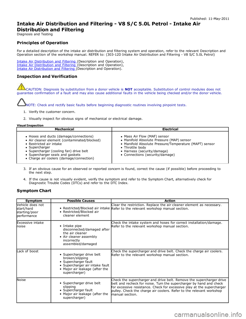
1. Verify the customer concern.
2. Visually inspect for obvious signs of mechanical or electrical damage.
Visual Inspection
Mechanical Electrical
Hoses and ducts (damage/connections)
Air cleaner element (contaminated/blocked)
Restricted air intake
Supercharger
Supercharger (cooling fan) drive belt
Supercharger seals and gaskets
Charge air coolers (damage/connection)
Mass Air Flow (MAF) sensor
Manifold Absolute Pressure (MAP) sensor
Manifold Absolute Pressure/Temperature (MAPT) sensor
Throttle body
Harness (security/damage)
Connections (security/damage)
3. If an obvious cause for an observed or reported concern is found, correct the cause (if possible) before proceeding to
the next step.
4. If the cause is not visually evident, verify the symptom and refer to the Symptom Chart, alternatively check for
Diagnostic Trouble Codes (DTCs) and refer to the DTC Index.
Symptom Chart
Symptom Possible Causes Action Vehicle does not
start/hard
starting/poor
performance
Restricted/Blocked air intake
Restricted/Blocked air
cleaner element Clear the restriction. Replace the air cleaner element as necessary.
Refer to the relevant workshop manual section. Excessive intake
noise
Intake pipe
disconnected/damaged after
the air cleaner
Air cleaner assembly
incorrectly
assembled/damaged Check the intake system and hoses for correct installation/damage.
Refer to the relevant workshop manual section. Lack of boost
Supercharger drive belt
broken/slipping
Supercharger fault
Supercharger air intake fault
Major air leakage (after the
supercharger) Check the supercharger and drive belt. Check the charge air coolers.
Refer to the relevant workshop manual section. Noise
Supercharger drive belt
slipping
Supercharger fault
Major air leakage (after the
supercharger) Check the supercharger and drive belt. Remove the supercharger drive
belt and recheck for noise. Turn the supercharger by hand and check
for excessive resistance. Check for excessive play at the supercharger
pulley. Check the charge air coolers. Refer to the relevant workshop
manual section.
Page 1361 of 3039
DIAGNOSTICS
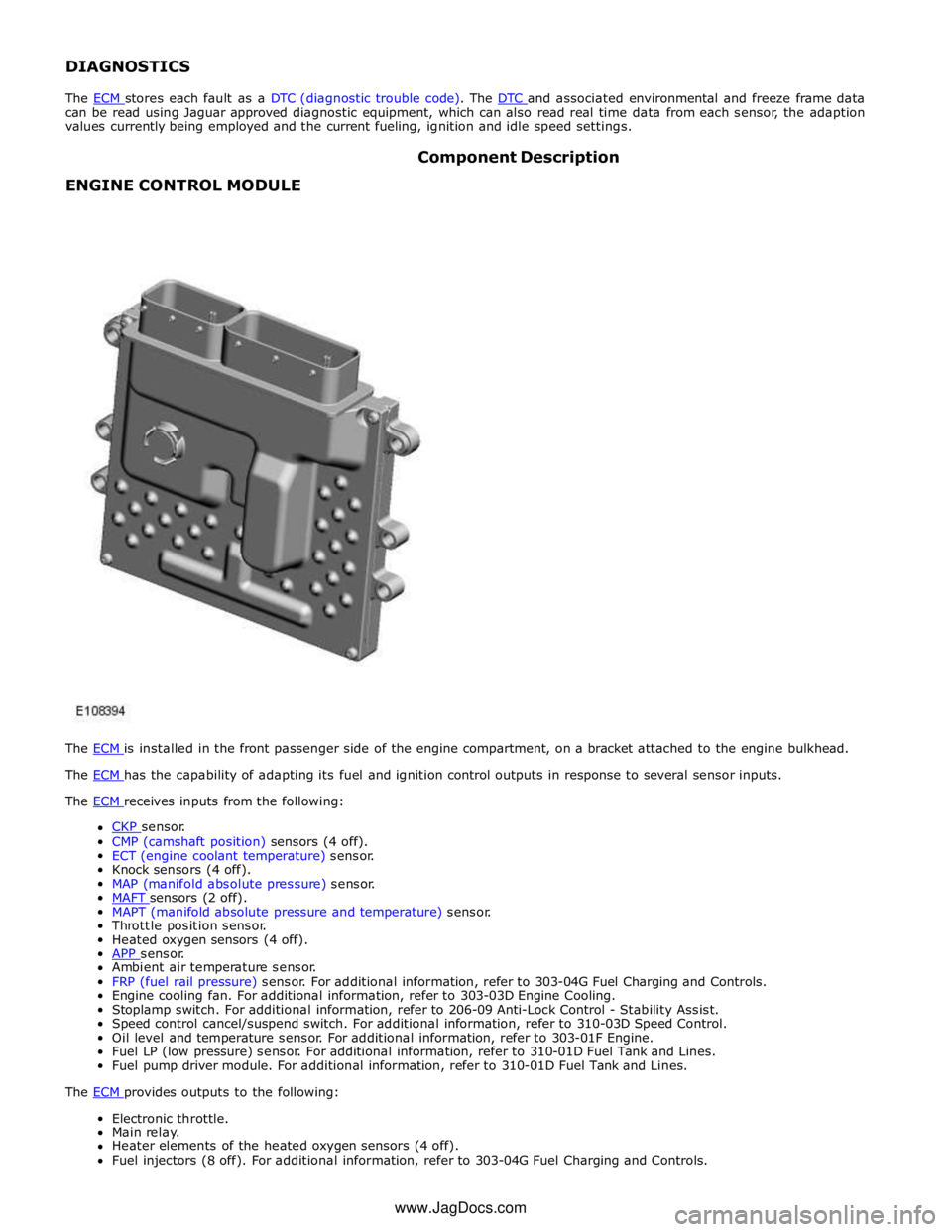
The ECM stores each fault as a DTC (diagnostic trouble code). The DTC and associated environmental and freeze frame data can be read using Jaguar approved diagnostic equipment, which can also read real time data from each sensor, the adaption
values currently being employed and the current fueling, ignition and idle speed settings.
ENGINE CONTROL MODULE Component Description
The ECM is installed in the front passenger side of the engine compartment, on a bracket attached to the engine bulkhead. The ECM has the capability of adapting its fuel and ignition control outputs in response to several sensor inputs. The ECM receives inputs from the following:
CKP sensor. CMP (camshaft position) sensors (4 off).
ECT (engine coolant temperature) sensor.
Knock sensors (4 off).
MAP (manifold absolute pressure) sensor.
MAFT sensors (2 off). MAPT (manifold absolute pressure and temperature) sensor.
Throttle position sensor.
Heated oxygen sensors (4 off).
APP sensor. Ambient air temperature sensor.
FRP (fuel rail pressure) sensor. For additional information, refer to 303-04G Fuel Charging and Controls.
Engine cooling fan. For additional information, refer to 303-03D Engine Cooling.
Stoplamp switch. For additional information, refer to 206-09 Anti-Lock Control - Stability Assist.
Speed control cancel/suspend switch. For additional information, refer to 310-03D Speed Control.
Oil level and temperature sensor. For additional information, refer to 303-01F Engine.
Fuel LP (low pressure) sensor. For additional information, refer to 310-01D Fuel Tank and Lines.
Fuel pump driver module. For additional information, refer to 310-01D Fuel Tank and Lines.
The ECM provides outputs to the following: Electronic throttle.
Main relay.
Heater elements of the heated oxygen sensors (4 off).
Fuel injectors (8 off). For additional information, refer to 303-04G Fuel Charging and Controls. www.JagDocs.com
Page 1363 of 3039
Defaults to base mapping for the ignition timing, with no cylinder correction
Disables the VCT system.
ENGINE COOLANT TEMPERATURE SENSORS
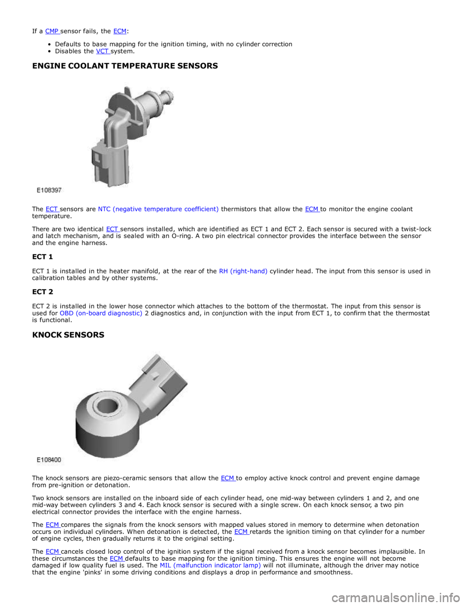
The ECT sensors are NTC (negative temperature coefficient) thermistors that allow the ECM to monitor the engine coolant temperature.
There are two identical ECT sensors installed, which are identified as ECT 1 and ECT 2. Each sensor is secured with a twist-lock and latch mechanism, and is sealed with an O-ring. A two pin electrical connector provides the interface between the sensor
and the engine harness.
ECT 1
ECT 1 is installed in the heater manifold, at the rear of the RH (right-hand) cylinder head. The input from this sensor is used in
calibration tables and by other systems.
ECT 2
ECT 2 is installed in the lower hose connector which attaches to the bottom of the thermostat. The input from this sensor is
used for OBD (on-board diagnostic) 2 diagnostics and, in conjunction with the input from ECT 1, to confirm that the thermostat
is functional.
KNOCK SENSORS
The knock sensors are piezo-ceramic sensors that allow the ECM to employ active knock control and prevent engine damage from pre-ignition or detonation.
Two knock sensors are installed on the inboard side of each cylinder head, one mid-way between cylinders 1 and 2, and one
mid-way between cylinders 3 and 4. Each knock sensor is secured with a single screw. On each knock sensor, a two pin
electrical connector provides the interface with the engine harness.
The ECM compares the signals from the knock sensors with mapped values stored in memory to determine when detonation occurs on individual cylinders. When detonation is detected, the ECM retards the ignition timing on that cylinder for a number of engine cycles, then gradually returns it to the original setting.
The ECM cancels closed loop control of the ignition system if the signal received from a knock sensor becomes implausible. In these circumstances the ECM defaults to base mapping for the ignition timing. This ensures the engine will not become damaged if low quality fuel is used. The MIL (malfunction indicator lamp) will not illuminate, although the driver may notice
that the engine 'pinks' in some driving conditions and displays a drop in performance and smoothness.
Page 1370 of 3039

Symptom Possible Cause Action (EGR) valve stuck open
Fuel pump
Evaporative emissions purge
valve care manual and the relevant sections of the
workshop manual.
Read DTCs and refer to DTC Index in this
section for electronic engine control tests
Refer to the relevant section of the
workshop manual and check the Exhaust Gas
Recirculation (EGR) valve and associated
hoses and connections.
For fuel system tests refer to the relevant
section of the workshop manual
Refer to the relevant section of the
workshop manual and check the purge valve
and associated hoses and connections. Difficult hot start
Injector leak
Electronic engine controls
Evaporative emissions purge
valve
Fuel pump
Ignition system
EGR valve stuck open
Refer to the relevant section of the
workshop manual, carry out injector leak
tests, install new injectors as necessary.
Read DTCs and refer to DTC Index in this
section for electronic engine control tests
Refer to the relevant section of the
workshop manual and check the purge valve
and associated hoses and connections.
For fuel system tests refer to the relevant
section of the workshop manual
For ignition system tests refer to the
relevant section of the workshop manual
Refer to the relevant section of the
workshop manual and check the Exhaust Gas
Recirculation (EGR) valve and associated
hoses and connections. Difficult to start after hot soak
(vehicle standing, engine off, after
engine has reached operating
temperature)
Injector leak
Electronic engine controls
Evaporative emissions purge
valve
Fuel pump
Ignition system
EGR valve stuck open
Refer to the relevant section of the
workshop manual, carry out injector leak
tests, install new injectors as necessary.
Read DTCs and refer to DTC Index in this
section for electronic engine control tests
Refer to the relevant section of the
workshop manual and check the purge valve
and associated hoses and connections.
For fuel system tests refer to the relevant
section of the workshop manual
For ignition system tests refer to the
relevant section of the workshop manual
Refer to the relevant section of the
workshop manual and check the Exhaust Gas
Recirculation (EGR) valve and associated
hoses and connections. Engine cranks too fast/slow
Compressions high/low
Battery
Starting system
Refer to the relevant section of the
workshop manual, carry out compression
tests.
Ensure the battery is in a fully charged and
serviceable condition. Refer to the battery
care manual and the relevant sections of the
workshop manual.
For starting system tests refer to the
relevant section of the workshop manual Engine stalls Engine stalls soon after start
Breather system
disconnected/restricted
ECM relay
Electronic engine controls
Ignition system
Air intake system restricted
Air leakage
Fuel lines
Ensure the engine breather system is free
from restriction and is correctly installed
Read DTCs and refer to DTC Index in this
section for ECM relay tests
Read DTCs and refer to DTC Index in this
section for electronic engine control tests
For ignition system tests refer to the
relevant section of the workshop manual
Check for blockage in air cleaner element
and air intake system
Check for leakage in air intake system
For fuel system tests refer to the relevant
section of the workshop manual
Page 1373 of 3039

DTC Description Possible Causes Action B10AC-81
Cruise Control Switch -
invalid serial data received
The Engine Control Module
(ECM) has received an invalid
command from the steering
wheel switch pack Clear the DTC and press all the steering wheel
switches, re-check for DTCs. Refer to the
electrical circuit diagrams and check the Cruise
control switch circuit for open circuit, short to
power, short to ground, disconnected. Check
and install a new Steering Wheel Module (SWM) as required. B10AC-82 Cruise Control Switch - alive / sequence counter incorrect / not updated
Cruise Buttons alive counter is
not incrementing. Which
suggests that the LIN bus is
faulty
Steering Wheel Module (SWM) is
not connected
Steering Wheel Module (SWM)
failure Refer to the electrical circuit diagrams and
check the Cruise control switch circuit for open
circuit, short to power, short to ground,
disconnected. Check and install a new Steering
Wheel Module (SWM) as required. B10AC-83
Cruise Control Switch - value
of signal protection
calculation incorrect
Cruise buttons checksum
incorrect, incorrect cruise
switches fitted to vehicle Check and install new cruise switches as
required. B10AC-96
Cruise Control Switch -
component internal failure
Cruise control switch circuit,
open circuit, short to power,
short to ground, disconnected
Cruise Control Switch failure
Steering Wheel Module (SWM)
failure Check for related DTCs in other Central
Junction Box (CJB)s. Refer to the electrical
circuit diagrams and check the Cruise control
switch circuit for open circuit, short to power,
short to ground, disconnected. Check and
install a new cruise control switch as required.
Check and install a new Steering Wheel
Module (SWM) as required. B10FF-68
Ignition Control - Event
information
Spark plug(s) fault
Wiring harness fault
Ignition coil(s) fault Refer to repair manual and check spark plug(s)
for condition and security. Replace any
defective components as required. Refer to
electrical wiring diagrams and check ignition
coil circuit for intermittent open circuit, short
to power, short to ground. Check and install a
new coil(s) as required. B11DB-01
Battery Monitoring Module -
General Electrical Failure
Charging system fault Battery
monitoring signal line
circuit fault
Vehicle battery fault Refer to electrical wiring diagrams and check
charging system for faults. Perform any repairs
required. Refer to the electrical wiring
diagrams and check the Battery Monitoring
System (BMS) module circuit for open circuit,
short to ground, short to power. Refer to the
battery care manual and check and install a
new battery. B11DB-87
Battery Monitoring Module -
missing message
Battery signal line circuit fault Refer to the electrical wiring diagrams and
check the Battery Monitoring System (BMS)
module circuit for open circuit, short to ground,
short to power. B1206-68
Crash Occurred - event
information
Engine control Module (ECM) has
detected the vehicle has crashed
- event information DTC only Refer to the electrical circuit diagrams and
check the Engine Control Module (ECM) to
Restraints Control Module (RCM) circuit for
short to ground, short to power, open circuit.
Repair circuit as required, clear DTC and retest
system to confirm repair. C0031-00
Left Front Wheel Speed
Sensor - No sub type
information
Invalid data received from
Anti-lock Braking System (ABS)
module - left front wheel speed
signal fault Check Anti-lock Braking System (ABS) module
for related DTCs and refer to relevant DTC
Index. C0034-00
Right Front Wheel Speed
Sensor - No sub type
information
Invalid data received from
Anti-lock Braking System (ABS)
module - right front wheel speed
signal fault Check Anti-lock Braking System (ABS) module
for related DTCs and refer to relevant DTC
Index. C0037-00
Left Rear Wheel Speed
Sensor - No sub type
information
Invalid data received from
Anti-lock Braking System (ABS)
module - left rear wheel speed
signal fault Check Anti-lock Braking System (ABS) module
for related DTCs and refer to relevant DTC
Index. C003A-00
Right Rear Wheel Speed
Sensor - No sub type
information
Invalid data received from
Anti-lock Braking System (ABS)
module - right rear wheel speed
signal fault Check Anti-lock Braking System (ABS) module
for related DTCs and refer to relevant DTC
Index.
Page 1388 of 3039
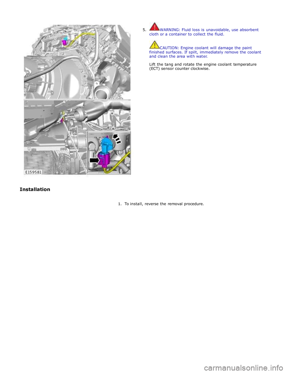
Installation 5. WARNING: Fluid loss is unavoidable, use absorbent
cloth or a container to collect the fluid.
CAUTION: Engine coolant will damage the paint
finished surfaces. If spilt, immediately remove the coolant
and clean the area with water.
Lift the tang and rotate the engine coolant temperature
(ECT) sensor counter clockwise.
1. To install, reverse the removal procedure.
Page 1410 of 3039
Published: 11-May-2011
Automatic Transmission/Transaxle - TDV6 3.0L Diesel /V8 5.0L Petrol/V8 S/C 5.0L Petrol - Transmission Description - Overview
Description and Operation
OVERVIEW
The ZF 6HP28 transmission is an electronically controlled, hydraulically operated, six speed automatic unit. The hydraulic and
electronic control elements of the transmission, including the TCM (transmission control module), are incorporated in a single
unit located inside the transmission and is known as 'Mechatronic'.
5.1 L SC (supercharger) and 3.0L diesel models use an uprated derivative of the ZF 6HP28 transmission used in the 5.0L
naturally aspirated models.
The ZF 6HP28 transmission has the following features:
Designed to be maintenance free
Transmission fluid is 'fill for life'
The torque converter features a controlled slip feature with electronically regulated control of lock-up, creating a smooth
transition to the fully locked condition
Shift programs controlled by the TCM Electronic park lock, controlled by the TCM, with a mechanical emergency release ASIS (adaptive shift strategy), to provide continuous adaptation of shift changes to suit the driving style of the driver,
which can vary from sporting to economical.
Connected to the ECM (engine control module) via the high speed CAN (controller area network) bus for communications
Default mode if major faults occur
Diagnostics available from the TCM via the high speed CAN bus.
The transmission selections are made using the rotary JaguarDrive selector in the floor console and two paddle switches on the
steering wheel. For additional information, refer to 307-05B Automatic Transmission/Transaxle External Controls - 5.0L/3.0L
Diesel).