Page 774 of 3039
Installation
1. Install the tie rod end, note the number of turns until adjacent to the
locknut.
2. CAUTION: Make sure that the ball joint ball does not rotate.
Connect the tie-rod end ball joint.
Clean the component mating faces.
Install a new nut and tighten to 133 Nm.
3. Tighten the tie-rod locking nut.
Clean the component mating faces.
Tighten the nut to 55 Nm.
4. Install the front wheel.
For additional information, refer to: Wheel and Tire (204-04 Wheels and Tires, Removal and Installation).
5. Using only four-wheel alignment equipment approved by Jaguar, check
and adjust the wheel alignment.
For additional information, refer to: Four-Wheel Alignment (204-00 Suspension System - General Information, General Procedures).
Page 776 of 3039
1 Steering wheel 2 Gear change paddle switch 3 Column adjust switch 4 Lower shroud 5 Rake adjustment housing 6 Reach adjustment housing 7 Column adjustment motor 8 Lower column - Upper collapse shaft 9 Bulkhead bearing and seal assembly 10 Lower column - Lower collapse shaft 11 Electric steering lock mechanism 12 Column mounting plate 13 Upper shroud
Page 777 of 3039

Steering Column - Steering Column - Overview
Description and Operation
OVERVIEW Published: 11-May-2011
The steering column comprises the upper column assembly, the lower column assembly and the steering wheel. The 3
components are positively connected together to pass driver rotary input from the steering wheel to a linear output of the
steering rack.
The upper column assembly contains electrical adjustment for steering wheel reach and rake, the electric steering lock
mechanism and the steering angle sensor. Steering adjustment memory positions are stored in the driver's seat module.
The electric steering column is a standard fitment on all models. The upper column assembly contains electrical adjustment for
steering wheel reach and rake, the electric column lock mechanism and the steering angle sensor. Steering adjustment memory
positions are stored in the driver's seat module. The column also features a 'tilt away' function which moves the steering
column away from the driver allowing easier exit and entry to the vehicle.
Column adjustment is provided by a single motor for both reach and rake adjustment. Operation of the column adjustment is
controlled by a four way joystick type switch located in the column lower shroud. Column adjustment is an integral part of the
driver position memory system.
www.JagDocs.com
Page 778 of 3039
Published: 20-May-2014
Steering Column - Steering Column - System Operation and Component Description
Description and Operation
Control Diagram
NOTE: A = Hardwired; D = High speed CAN bus; N = Medium speed CAN bus
Item Description 1 Battery 2 BJB (battery junction box) - Megafuse (175A) 3 RJB (rear junction box) 4 Electric steering column lock 5 High Speed CAN (controller area network) bus to other vehicle systems 6 CJB (central junction box)
Page 779 of 3039

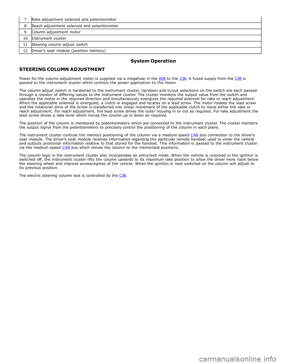
8 Reach adjustment solenoid and potentiometer 9 Column adjustment motor 10 Instrument cluster 11 Steering column adjust switch 12 Driver's seat module (position memory)
STEERING COLUMN ADJUSTMENT System Operation
Power for the column adjustment motor is supplied via a megafuse in the BJB to the CJB. A fused supply from the CJB is passed to the instrument cluster which controls the power application to the motor.
The column adjust switch is hardwired to the instrument cluster. Up/down and in/out selections on the switch are each passed
through a resistor of differing values to the instrument cluster. The cluster monitors the output value from the switch and
operates the motor in the required direction and simultaneously energizes the required solenoid for rake or reach adjustment.
When the applicable solenoid is energized, a clutch is engaged and locates on a lead screw. The motor rotates the lead screw
and the rotational drive of the screw is transferred into linear movement of the applicable clutch to move either the rake or
reach adjustment. For reach adjustment, the lead screw drives the outer housing in or out as required. For rake adjustment the
lead screw drives a rake lever which moves the column up or down as required.
The position of the column is monitored by potentiometers which are connected to the instrument cluster. The cluster monitors
the output signal from the potentiometers to precisely control the positioning of the column in each plane.
The instrument cluster controls the memory positioning of the column via a medium speed CAN bus connection to the driver's seat module. The driver's seat module receives information regarding the particular remote handset used to enter the vehicle
and outputs positional information relative to that stored for the handset. This information is passed to the instrument cluster
via the medium speed CAN bus which moves the column to the memorized positions.
The column logic in the instrument cluster also incorporates an entry/exit mode. When the vehicle is unlocked or the ignition is
switched off, the instrument cluster lifts the column upwards to its maximum rake position to allow the driver more room below
the steering wheel and improve access/egress of the vehicle. When the ignition is next switched on the column will adjust to
its previous position.
The electric steering column lock is controlled by the CJB.
Page 780 of 3039
STEERING COLUMN Component Description
Item Description 1 Rake housing 2 Electric steering column lock 3 Mounting plate 4 Rake lever 5 Crash tube 6 Distance keeper 7 Steering wheel mounting splines 8 Steering angle sensor ring 9 Crash adaptor 10 Rake lever pivot bearing (2 off) 11 Flanged locknut (4 off) - mounting to cross-beam 12 Rake solenoid 13 Rake clutch 14 Spindle 15 Reach solenoid 16 Reach clutch 17 Column adjustment motor 18 Outer clamping yoke 19 Clamp bolt 20 Inner tube yoke
WARNING: Do not attempt to dismantle the steering column. The crash safety of the unit will be compromised.
The steering column is attached to the in-vehicle cross-beam and secured with 4 flanged lock nuts onto 4 studs integral with
the cross-beam.
Page 781 of 3039
1 Tube and clamping yoke pivot bearing 2 Tube yoke 3 Tolerance ring 4 Locking ring 5 Axial housing 6 Rake housing 7 Tube 8 Splined shaft 9 Crash adaptor 10 Steering angle sensor ring 11 Steering wheel mounting splines 12 Upper bearing 13 Column adjustment motor 14 Lower bearing
Page 782 of 3039

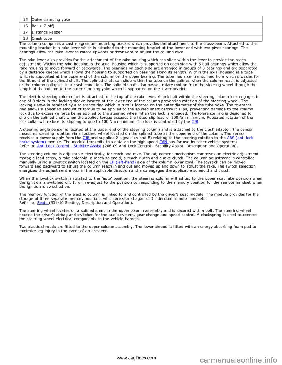
16 Ball (12 off) 17 Distance keeper 18 Crash tube The column comprises a cast magnesium mounting bracket which provides the attachment to the cross-beam. Attached to the
mounting bracket is a rake lever which is attached to the mounting bracket at the lower end with two pivot bearings. The
bearings allow the rake lever to rotate upwards or downward to adjust the column rake.
The rake lever also provides for the attachment of the rake housing which can slide within the lever to provide the reach
adjustment. Within the rake housing is the axial housing which is supported on each side with 6 ball bearings which allow the
rake housing to move forward or backwards. The bearings on each side are arranged in groups of 3 bearings and are separated
by a distance keeper which allows the housing to supported on bearings along its length. Within the axial housing is a tube
which is supported at the upper end of the column on the upper bearing. The tube has a central splined hole which provides for
the fitment of the splined shaft. The splined shaft can slide within the tube on the splines when the column reach is adjusted
or the column collapses in a crash condition. The splined shaft also passes rotary motion from the steering wheel through the
length of the column to the outer clamping yoke which is supported on the lower bearing.
The electric steering column lock is attached to the top of the rake lever. A lock bolt within the steering column lock engages in
one of 8 slots in the locking sleeve located at the lower end of the column preventing rotation of the steering wheel. The
locking sleeve is retained by a tolerance ring which in turn is located on the outer diameter of the tube yoke. The tolerance
ring allows a specified amount of torque to be applied to the splined shaft before it slips, preventing damage to the column
lock due to excessive force being applied to the steering wheel when the lock is engaged. The tolerance ring is designed to
slip on the splined shaft when the applied torque exceeds the fitted slip load of 200 Nm minimum. Repeated rotation of the
lock collar will reduce its slipping torque to 100 Nm minimum. The lock is controlled by the CJB.
A steering angle sensor is located at the upper end of the steering column and is attached to the crash adaptor. The sensor
measures steering rotation via a toothed wheel located on the splined tube at the upper end of the column. The sensor
receives a power supply from the CJB and supplies 2 signals (A and B) relating to the steering rotation to the ABS (anti-lock brake system) module. The module transmits this data on the high speed CAN bus for use by other vehicle systems. Refer to: Anti-Lock Control - Stability Assist (206-09 Anti-Lock Control - Stability Assist, Description and Operation).
The steering column is adjustable electrically, for reach and rake. The adjustment mechanism comprises an electric adjustment
motor, a lead screw, a rake solenoid, a reach solenoid, a reach clutch and a rake clutch. The column adjustment is controlled
manually using a joystick switch located on the LH (left-hand) side of the column lower cowl. The joystick can be moved
forward and backward to adjust the column reach in and out and moved up and down to adjust the rake. The switch selection
energizes the adjustment motor in the applicable direction and also engages the applicable solenoid and clutch.
When the joystick switch is rotated to the 'auto' position, the steering column will adjust to the uppermost rake position when
the ignition is switched off. It will re-adjust to the position corresponding to the memory position for the remote handset when
the ignition is switched on.
The memory function of the electric column is linked to and controlled by the driver's seat module. The module provides for the
storage of three separate memory positions which are stored against 3 individual remote handsets.
Refer to: Seats (501-10 Seating, Description and Operation).
The steering wheel locates on a splined shaft in the upper column assembly and is secured with a bolt. The steering wheel
houses the driver's airbag and switches for the audio system, gear change and speed control. A clockspring is used to connect
the steering wheel electrical components to the vehicle harness.
Two plastic shrouds are fitted to the upper column assembly. The lower shroud is fitted with an energy absorbing foam pad to
minimize leg injury in the event of an accident.
www.JagDocs.com