2010 JAGUAR XFR temperature
[x] Cancel search: temperaturePage 1666 of 3039

TEST
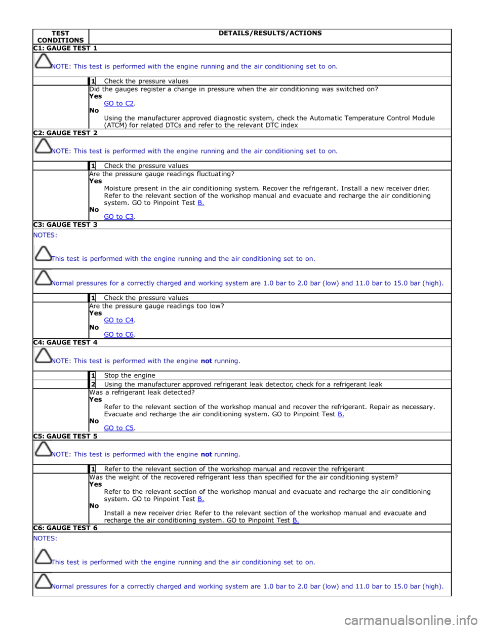
CONDITIONS DETAILS/RESULTS/ACTIONS C1: GAUGE TEST 1
NOTE: This test is performed with the engine running and the air conditioning set to on. 1 Check the pressure values Did the gauges register a change in pressure when the air conditioning was switched on? Yes
GO to C2. No
Using the manufacturer approved diagnostic system, check the Automatic Temperature Control Module (ATCM) for related DTCs and refer to the relevant DTC index C2: GAUGE TEST 2
NOTE: This test is performed with the engine running and the air conditioning set to on. 1 Check the pressure values Are the pressure gauge readings fluctuating? Yes
Moisture present in the air conditioning system. Recover the refrigerant. Install a new receiver drier.
Refer to the relevant section of the workshop manual and evacuate and recharge the air conditioning
system. GO to Pinpoint Test B. No
GO to C3. C3: GAUGE TEST 3 NOTES:
This test is performed with the engine running and the air conditioning set to on.
Normal pressures for a correctly charged and working system are 1.0 bar to 2.0 bar (low) and 11.0 bar to 15.0 bar (high). 1 Check the pressure values Are the pressure gauge readings too low? Yes
GO to C4. No
GO to C6. C4: GAUGE TEST 4
NOTE: This test is performed with the engine not running. 1 Stop the engine 2 Using the manufacturer approved refrigerant leak detector, check for a refrigerant leak Was a refrigerant leak detected? Yes
Refer to the relevant section of the workshop manual and recover the refrigerant. Repair as necessary.
Evacuate and recharge the air conditioning system. GO to Pinpoint Test B. No
GO to C5. C5: GAUGE TEST 5
NOTE: This test is performed with the engine not running. 1 Refer to the relevant section of the workshop manual and recover the refrigerant Was the weight of the recovered refrigerant less than specified for the air conditioning system? Yes
Refer to the relevant section of the workshop manual and evacuate and recharge the air conditioning
system. GO to Pinpoint Test B. No
Install a new receiver drier. Refer to the relevant section of the workshop manual and evacuate and recharge the air conditioning system. GO to Pinpoint Test B. C6: GAUGE TEST 6 NOTES:
This test is performed with the engine running and the air conditioning set to on.
Normal pressures for a correctly charged and working system are 1.0 bar to 2.0 bar (low) and 11.0 bar to 15.0 bar (high).
Page 1687 of 3039

7 RH (right-hand) outer face level register 8 RH inner face level register 9 LH (left-hand) inner face level register 10 LH outer face level register 11 Face/Feet distribution stepper motor 12 RH temperature blend stepper motor 13 Windshield (defrost) distribution stepper motor 14 LH temperature blend stepper motor
Face Level Registers System Operation
Operation of the face level registers is controlled by the ATC module, using LIN bus messages to the integral stepper motors. The four registers operate together in both the opening and closing phases.
The face level registers can be selected to run in one of two modes; 'automatic' or 'always open'. The mode is selected on the
climate control screen of the TSD.
Refer to: Navigation System (415-01 Information and Entertainment System, Description and Operation).
In the automatic mode, operation of the face level registers is synchronized with the engine START/STOP button. When the
engine starts the ATC module opens the registers. When the engine stops, the ATC module closes the registers.
If a face level register is fouled, when it receives an open or close request, the register concerned makes a number of
attempts to reach the requested position. If the register still does not move, it is left in the fouled position. The remaining
registers will continue to open and close as normal.
The automatic mode is disabled when the climate control system is off. The ATC module closes the registers if they are open in the automatic mode and the climate control system is selected off.
Diagnostics
If a fault occurs with the face level registers, a DTC (diagnostic trouble code) is stored in the ATC module. The DTC can be read using the Jaguar approved diagnostic system. The Jaguar approved diagnostic system can also initiate a self test routine
to check the operation of the face level registers.
Refer to: Climate Control System (412-00 Climate Control System - General Information, Diagnosis and Testing).
Air Ducts Component Description
The air ducts distribute air from the heater assembly to the registers and vents in the instrument panel and the center floor
console. Air ducts also direct air from the heater assembly into the front and rear footwells.
Registers and Vents
The registers control the flow and direction of air from the air ducts. The instrument panel contains four face level registers;
one at each end and two mounted centrally. For the rear seat occupants, two registers are installed in the rear face of the
center floor console. All of the registers incorporate vertical and horizontal directional vane adjustment and full air flow
adjustment down to zero.
The four face level registers in the instrument panel each contain an integral stepper motor. The stepper motors enable the
registers to rotate between the open and closed positions. In the open position, the registers have normal appearance and
functionality. In the closed position, the registers present a smooth surface flush with the surrounding instrument panel.
The vents are fixed outlets. There are four vents in the upper surface of the instrument panel; one in each end to direct air
onto the side windows and two along the front edge to direct air onto the windshield.
Central Face Level Registers
www.JagDocs.com
Page 1690 of 3039

Published: 11-May-2011
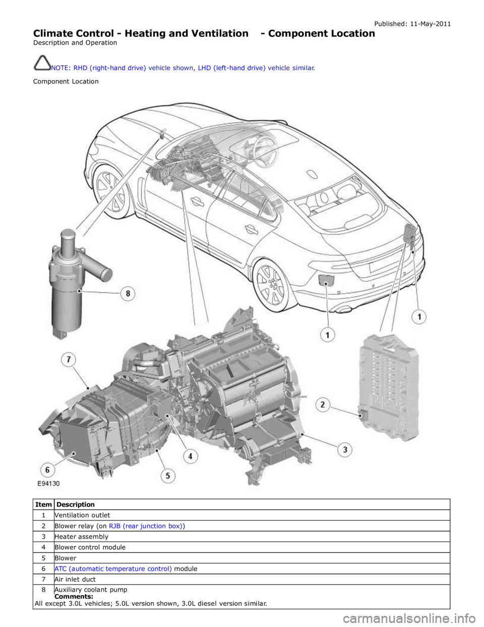
Climate Control - Heating and Ventilation - Component Location
Description and Operation
NOTE: RHD (right-hand drive) vehicle shown, LHD (left-hand drive) vehicle similar.
Component Location
Item Description 1 Ventilation outlet 2 Blower relay (on RJB (rear junction box)) 3 Heater assembly 4 Blower control module 5 Blower 6 ATC (automatic temperature control) module 7 Air inlet duct 8 Auxiliary coolant pump Comments:
All except 3.0L vehicles; 5.0L version shown, 3.0L diesel version similar.
Page 1691 of 3039

Climate Control - Heating and Ventilation - Overview
Description and Operation
Overview Published: 11-May-2011
The heating and ventilation system controls the temperature and flow of air supplied to the passenger compartment. The
system is a dual zone automatic system, which can provide different temperature settings for the LH (left-hand) and RH
(right-hand) sides of the passenger compartment.
Page 1693 of 3039

Touch screen display (TSD) 6 Integrated control panel 7 Information control module 8 ATC (automatic temperature control) module 9 Face/Feet distribution stepper motor 10 RH (right-hand) temperature blend stepper motor 11 LH (left-hand) temperature blend stepper motor 12 Windshield (defrost) distribution stepper motor 13 Blower control module 14 RJB (rear junction box) 15 Blower
System Operation
Operation of the heating and ventilation system is controlled by the ATC module. Refer to: Control Components (412-01 Climate Control, Description and Operation).
The system can be operated in automatic or manual mode, with temperature settings selected using the switches on the
integrated control panel.
When the engine is running, coolant is constantly circulated through the heater core by the engine coolant pump and the
auxiliary coolant pump. Where fitted, the auxiliary coolant pump is energized by the CJB on receipt of medium speed CAN bus signals from the ATC module. The CJB broadcasts auxiliary coolant pump status over the medium speed CAN bus for use by other vehicle systems.
The blower is supplied with power by the blower relay on the RJB and connected to ground via the blower control module. The blower control module regulates the voltage across the blower motor to control blower speed. The voltage set by the blower
control module is controlled by a PWM (pulse width modulation) signal from the ATC module. The ATC module uses a feedback signal from the blower control module to monitor blower speed.
Refer to: Control Components (412-01 Climate Control, Description and Operation).
Heater Assembly Component Description
The heater assembly controls the temperature and flow of air supplied to the air distribution ducts. The heater assembly is
mounted on the vehicle centerline, between the instrument panel and the engine bulkhead.
The heater assembly consists of a casing that contains an A/C (air conditioning) evaporator, a heater core, two air distribution
control doors and two temperature blend control doors. On 2.7L diesel vehicles, the heater assembly also contains an electric
booster heater.
Refer to: Electric Booster Heater (412-02 Auxiliary Climate Control, Description and Operation).
Mounted on the heater casing are four stepper motors. Each of the stepper motors is connected to either an air distribution
control door or a temperature blend control door.
The A/C evaporator is part of the A/C system. Refer to: Air Conditioning (412-01 Climate Control, Description and Operation).
The heater core provides the heat source to warm the air supplied to the passenger compartment. The heater core is an
aluminum two pass, fin and tube heat exchanger, and is installed across the width of the heater housing. Two aluminum tubes
attached to the heater core extend through the engine bulkhead and connect to the engine cooling system. For additional
information, refer to:
Engine Cooling (303-03A, Description and Operation),
Engine Cooling (303-03B Engine Cooling - V6 3.0L Petrol, Description and Operation), Engine Cooling (303-03C, Description and Operation).
Air Inlet Duct
The air inlet duct connects the fresh air inlet in the engine bulkhead to the heater assembly. The air inlet duct is installed
behind the instrument panel on the passenger side.
The air inlet duct consists of a casing that contains a pollen filter, an air inlet door, a blower and a blower control module. A
recirculation air inlet is incorporated into the casing. A servo motor is mounted on the casing and connected to the air inlet
door, to allow selection between fresh and recirculated air.
Refer to: Control Components (412-01 Climate Control, Description and Operation). The pollen filter is part of the air distribution and filtering system.
Refer to: Air Distribution and Filtering (412-01 Climate Control, Description and Operation).
The blower regulates the volume of air flowing through the air inlet duct to the heater assembly. The blower consists of an
open hub, centrifugal fan and an electric motor.
The blower control module regulates the power supply to the blower motor. The blower control module is installed in the air
Page 1698 of 3039

Published: 11-May-2011
Climate Control - Air Conditioning - System Operation and Component Description
Description and Operation
General System Operation
To accomplish the transfer of heat, refrigerant is circulated around a sealed system, where it passes through two
pressure/temperature regimes. In each of the regimes the refrigerant changes state, during which process maximum heat
absorption or dissipation occurs.
The low pressure/temperature regime is from the thermostatic expansion valve, through the evaporator to the compressor. The
refrigerant decreases in pressure and temperature at the thermostatic expansion valve, then changes state from a liquid to a
vapor in the evaporator to absorb heat.
The high pressure/temperature regime is from the compressor, through the condenser and receiver drier assembly to the
thermostatic expansion valve. The refrigerant increases in pressure and temperature as it passes through the compressor, then
releases heat and changes state from a vapor to a liquid in the condenser.
Operation of the A/C (air conditioning) system is controlled by the ATC (automatic temperature control) module.
Refer to: Control Components (412-01 Climate Control, Description and Operation). The A/C system works in conjunction with: The air distribution and filtering system.
Refer to: Air Distribution and Filtering (412-01 Climate Control, Description and Operation). The heating and ventilation system.
Refer to: Heating and Ventilation (412-01 Climate Control, Description and Operation).
Page 1700 of 3039

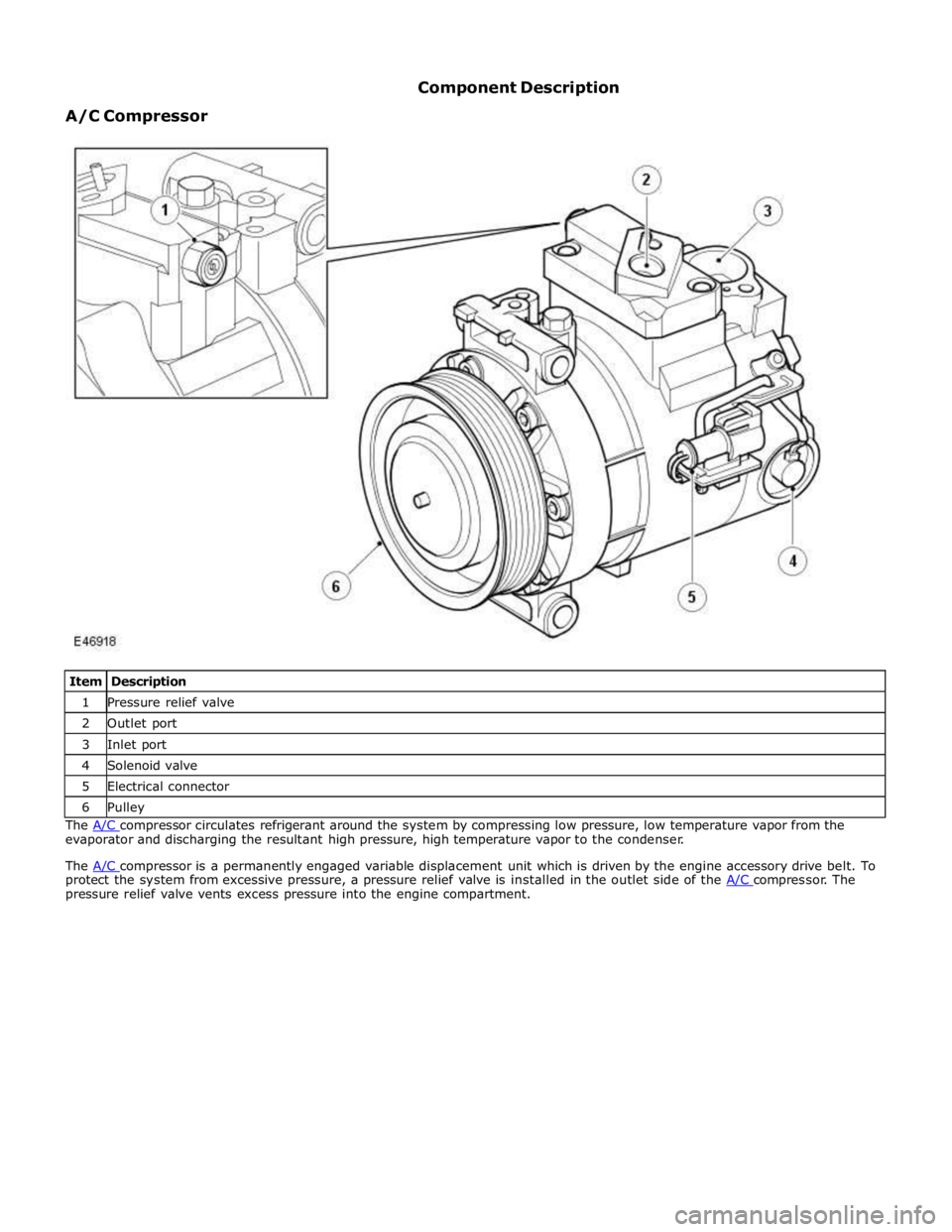
1 Pressure relief valve 2 Outlet port 3 Inlet port 4 Solenoid valve 5 Electrical connector 6 Pulley The A/C compressor circulates refrigerant around the system by compressing low pressure, low temperature vapor from the evaporator and discharging the resultant high pressure, high temperature vapor to the condenser.
The A/C compressor is a permanently engaged variable displacement unit which is driven by the engine accessory drive belt. To protect the system from excessive pressure, a pressure relief valve is installed in the outlet side of the A/C compressor. The pressure relief valve vents excess pressure into the engine compartment.
Page 1702 of 3039

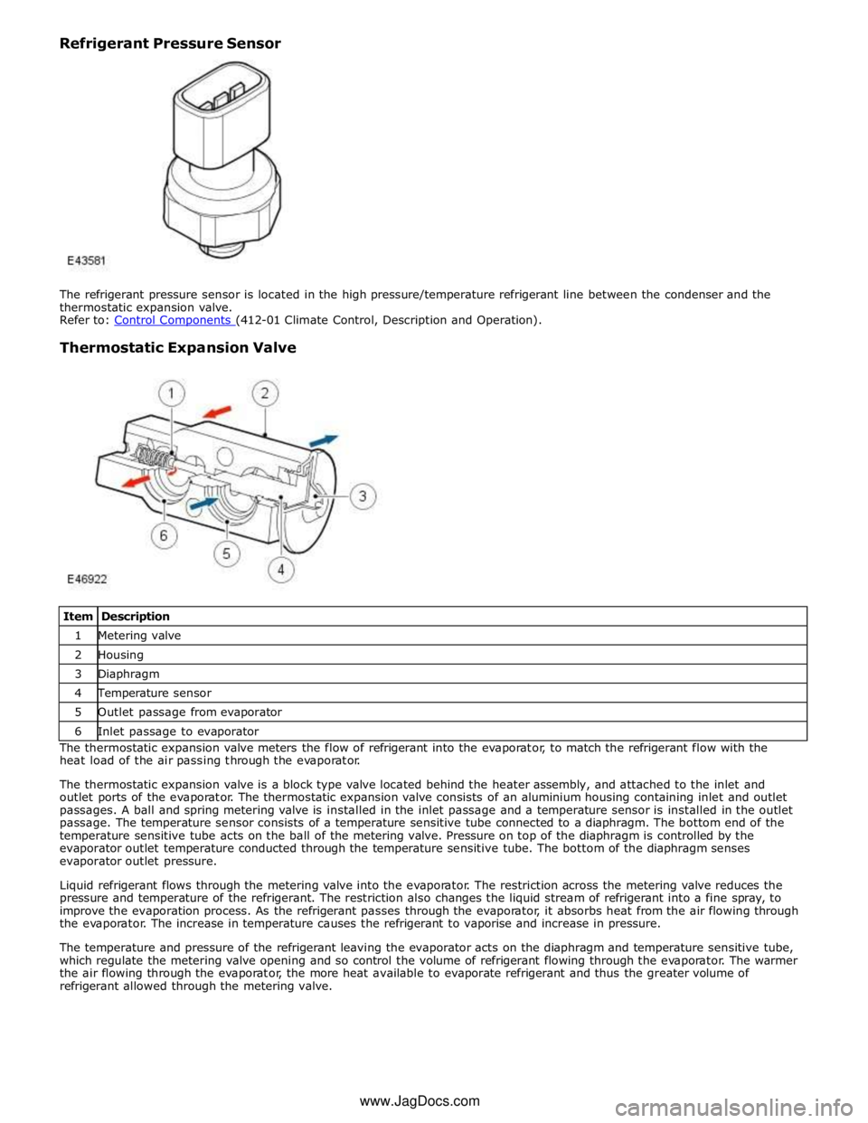
Thermostatic Expansion Valve
Item Description 1 Metering valve 2 Housing 3 Diaphragm 4 Temperature sensor 5 Outlet passage from evaporator 6 Inlet passage to evaporator The thermostatic expansion valve meters the flow of refrigerant into the evaporator, to match the refrigerant flow with the
heat load of the air passing through the evaporator.
The thermostatic expansion valve is a block type valve located behind the heater assembly, and attached to the inlet and
outlet ports of the evaporator. The thermostatic expansion valve consists of an aluminium housing containing inlet and outlet
passages. A ball and spring metering valve is installed in the inlet passage and a temperature sensor is installed in the outlet
passage. The temperature sensor consists of a temperature sensitive tube connected to a diaphragm. The bottom end of the
temperature sensitive tube acts on the ball of the metering valve. Pressure on top of the diaphragm is controlled by the
evaporator outlet temperature conducted through the temperature sensitive tube. The bottom of the diaphragm senses
evaporator outlet pressure.
Liquid refrigerant flows through the metering valve into the evaporator. The restriction across the metering valve reduces the
pressure and temperature of the refrigerant. The restriction also changes the liquid stream of refrigerant into a fine spray, to
improve the evaporation process. As the refrigerant passes through the evaporator, it absorbs heat from the air flowing through
the evaporator. The increase in temperature causes the refrigerant to vaporise and increase in pressure.
The temperature and pressure of the refrigerant leaving the evaporator acts on the diaphragm and temperature sensitive tube,
which regulate the metering valve opening and so control the volume of refrigerant flowing through the evaporator. The warmer
the air flowing through the evaporator, the more heat available to evaporate refrigerant and thus the greater volume of
refrigerant allowed through the metering valve. www.JagDocs.com