2010 JAGUAR XFR temperature
[x] Cancel search: temperaturePage 1374 of 3039
Published: 11-May-2011
Electronic Engine Controls - V8 S/C 5.0L Petrol - Powertrain Control Module
(PCM) Long Drive Cycle Self-Test
General Procedures
WARNING: Where possible, all road tests should be on well surfaced and dry roads. Always comply with speed limits and
local traffic regulations.
NOTES:
This procedure is an overcheck only. If fault codes are found, interrogation of the relevant system must be carried out and
claimed against.
The vehicle must exceed 50mph (80 km/h) during the road test.
1. Connect the diagnostic equipment to the vehicle.
2. Follow on screen prompts and check for engine management fault codes.
3. Clear the fault codes following the on screen procedure.
4. Disconnect the diagnostic equipment from the vehicle.
5. NOTE: Make sure cruise control is not engaged. Make sure
the engine temperature is above 60 ºC (140 ºF).
Carry out a road test and perform the following operations.
1. Accelerate to 55 mph (88 km/h) in 5th gear and cruise for 2
minutes with the engine speed at or above 1800rpm.
2. Lift off the throttle and allow the vehicle to decelerate until the
engine speed is less than 1000 rpm.
3. Stop the vehicle.
4. Release brake, allow the vehicle to move with no throttle for 1
minute.
5. Road test is now complete.
6. Connect the diagnostic equipment to the vehicle.
7. NOTE: If fault codes are found, interrogation of the relevant
system must be carried out and claimed against.
Follow on screen prompts and check for engine management fault codes.
8. Disconnect the diagnostic equipment from the vehicle.
Page 1375 of 3039
Published: 11-May-2011
Electronic Engine Controls - V8 S/C 5.0L Petrol - Powertrain Control Module
(PCM) Short Drive Cycle Self-Test
General Procedures
NOTE: This procedure is an overcheck only. If fault codes are found, interrogation of the relevant system must be carried
out and claimed against.
1. Connect the diagnostic equipment to the vehicle.
2. Follow on screen prompts and check for engine management fault codes.
3. Clear the fault codes following the on screen procedure.
4. Start the engine.
Allow the engine to idle for 30 seconds.
Raise the engine speed to 1500 rpm and hold for 3 minutes until
a temperature of 70ºC (158 ºF) is achieved.
Allow the engine to idle for 30 seconds.
Switch off the engine.
5. NOTE: If fault codes are found, interrogation of the relevant
system must be carried out and claimed against.
Follow on screen prompts and check for engine management fault codes.
6. Disconnect the diagnostic equipment from the vehicle.
Page 1387 of 3039
Published: 19-Aug-2013
Electronic Engine Controls - V8 S/C 5.0L Petrol - Engine Coolant Temperature
(ECT) Sensor
Removal and Installation
Removal
NOTES:
Some variation in the illustrations may occur, but the essential information is always correct.
Removal steps in this procedure may contain installation details.
1. WARNING: Do not work on or under a vehicle supported only by a jack.
Always support the vehicle on safety stands.
Raise and support the vehicle.
2. Refer to: Cooling System Partial Draining, Filling and Bleeding (303-03B Engine Cooling - V6 3.0L Petrol, General Procedures).
3. Refer to: Catalytic Converter RH (309-00C Exhaust System - V8 5.0L Petrol/V8 S/C 5.0L Petrol, Removal and Installation).
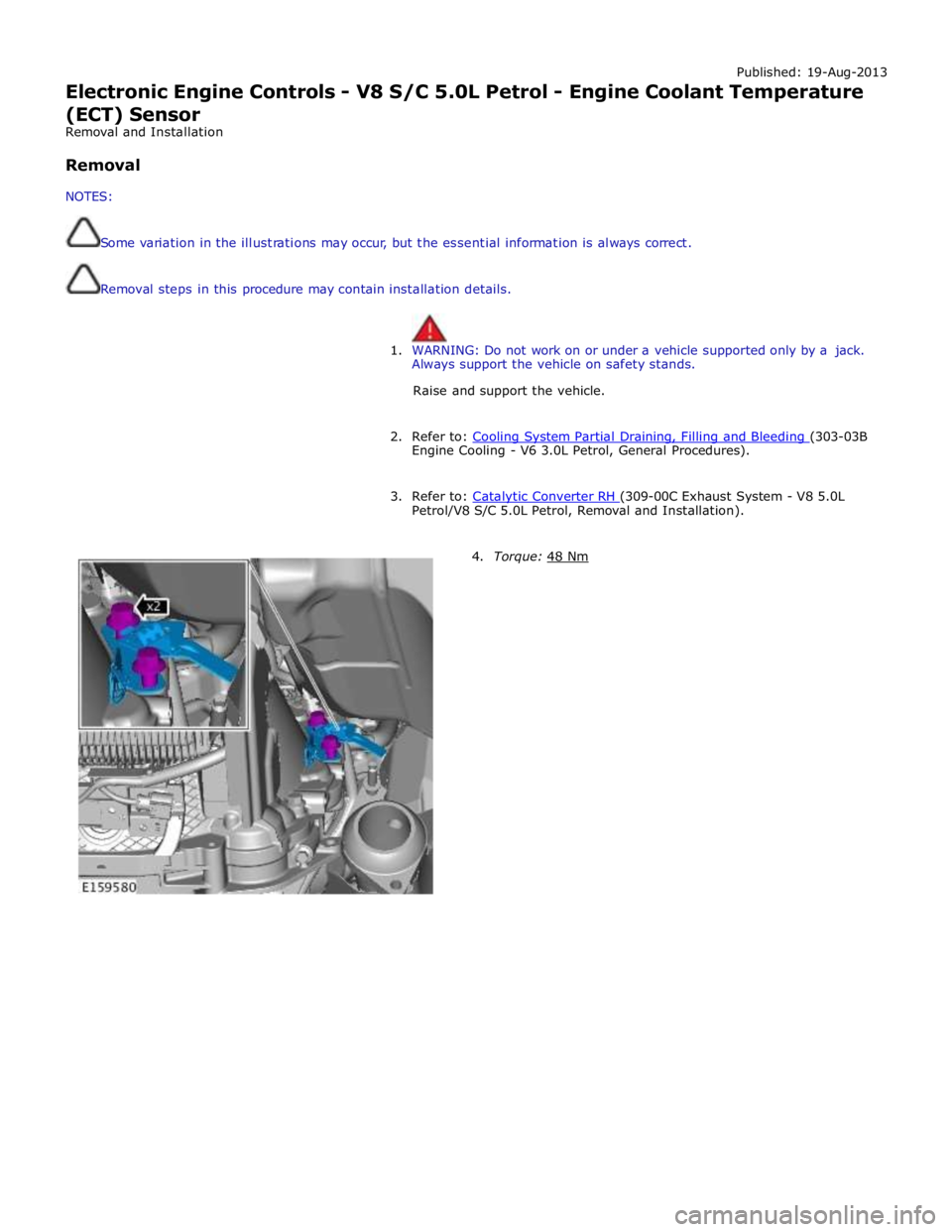
4. Torque: 48 Nm
Page 1388 of 3039
Installation 5. WARNING: Fluid loss is unavoidable, use absorbent
cloth or a container to collect the fluid.
CAUTION: Engine coolant will damage the paint
finished surfaces. If spilt, immediately remove the coolant
and clean the area with water.
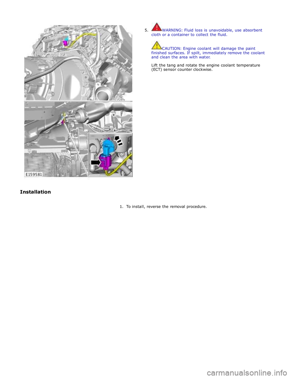
Lift the tang and rotate the engine coolant temperature
(ECT) sensor counter clockwise.
1. To install, reverse the removal procedure.
Page 1408 of 3039
Published: 11-May-2011
Automatic Transmission/Transaxle - TDV6 3.0L Diesel /V8 5.0L Petrol/V8 S/C 5.0L Petrol -
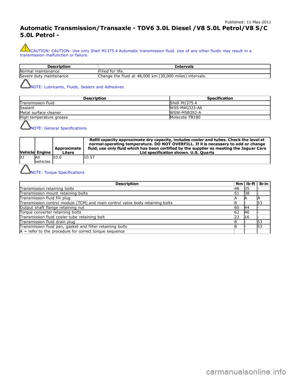
CAUTION: CAUTION: Use only Shell M1375.4 Automatic transmission fluid. Use of any other fluids may result in a
transmission malfunction or failure.
Description Intervals Normal maintenance Filled for life. Severe duty maintenance Change the fluid at 48,000 km (30,000 miles) intervals.
NOTE: Lubricants, Fluids, Sealers and Adhesives
Description Specification Transmission fluid Shell M1375.4 Sealant WSS-M4G323-A6 Metal surface cleaner WSW-M5B392-A High temperature grease Molecote FB180
NOTE: General Specifications
Vehicle
Engine
Approximate
Liters Refill capacity approximate dry capacity, includes cooler and tubes. Check the level at
normal operating temperature. DO NOT OVERFILL. If it is necessary to add or change
fluid, use only fluid which has been certified by the supplier as meeting the Jaguar Cars
Ltd specification shown. U.S. Quarts XJ
All
vehicles 10.0 10.57
NOTE: Torque Specifications
Description Nm lb-ft lb-in Transmission retaining bolts 48 35 - Transmission mount retaining bolts 51 38 - Transmission fluid fill plug A A A Transmission control module (TCM) and main control valve body retaining bolts 8 - 53 Output shaft flange retaining nut 60 44 - Torque converter retaining bolts 62 46 - Transmission fluid cooler tube retaining bolt 22 16 - Transmission fluid drain plug 8 - 53 Transmission fluid pan, gasket and filter retaining bolts 8 - 53 A = refer to the procedure for correct torque sequence
Page 1422 of 3039
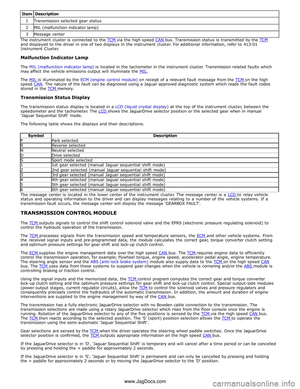
1 Transmission selected gear status 2 MIL (malfunction indicator lamp) 3 Message center The instrument cluster is connected to the TCM via the high speed CAN bus. Transmission status is transmitted by the TCM and displayed to the driver in one of two displays in the instrument cluster. For additional information, refer to 413-01
Instrument Cluster.
Malfunction Indicator Lamp
The MIL (malfunction indicator lamp) is located in the tachometer in the instrument cluster. Transmission related faults which
may affect the vehicle emissions output will illuminate the MIL.
The MIL is illuminated by the ECM (engine control module) on receipt of a relevant fault message from the TCM on the high speed CAN. The nature of the fault can be diagnosed using a Jaguar approved diagnostic system which reads the fault codes stored in the TCM memory.
Transmission Status Display
The transmission status display is located in a LCD (liquid crystal display) at the top of the instrument cluster, between the
speedometer and the tachometer. The LCD shows the JaguarDrive selector position or the selected gear when in manual 'Jaguar Sequential Shift' mode.
The following table shows the displays and their descriptions.
Symbol Description P Park selected R Reverse selected N Neutral selected D Drive selected S Sport mode selected 1 1st gear selected (manual Jaguar sequential shift mode) 2 2nd gear selected (manual Jaguar sequential shift mode) 3 3rd gear selected (manual Jaguar sequential shift mode) 4 4th gear selected (manual Jaguar sequential shift mode) 5 5th gear selected (manual Jaguar sequential shift mode) 6 6th gear selected (manual Jaguar sequential shift mode) The message center is located in the lower center of the instrument cluster. The message center is a LCD to relay vehicle status and operating information to the driver and can display messages relating to a number of the vehicle systems. If a
transmission fault occurs, the message center will display the message 'GEARBOX FAULT'.
TRANSMISSION CONTROL MODULE
The TCM outputs signals to control the shift control solenoid valve and the EPRS (electronic pressure regulating solenoid) to control the hydraulic operation of the transmission.
The TCM processes signals from the transmission speed and temperature sensors, the ECM and other vehicle systems. From the received signal inputs and pre-programmed data, the module calculates the correct gear, torque converter clutch setting
and optimum pressure settings for gear shift and lock-up clutch control.
The ECM supplies the engine management data over the high speed CAN bus. The TCM requires engine data to efficiently control the transmission operation, for example; flywheel torque, engine speed, accelerator pedal angle, engine temperature.
The steering angle sensor and the ABS (anti-lock brake system) module also supply data to the TCM on the high speed CAN bus. The TCM uses data from these systems to suspend gear changes when the vehicle is cornering and/or the ABS module is controlling braking or traction control.
Using the signal inputs and the memorized data, the TCM control program computes the correct gear and torque converter lock-up clutch setting and the optimum pressure settings for gear shift and lock-up clutch control. Special output-side modules
(power output stages, current regulator circuits), allow the TCM to control the solenoid valves and pressure regulators and consequently precisely control the hydraulics of the automatic transmission. In addition, the amount and duration of engine
interventions are supplied to the engine management by way of the CAN bus.
The transmission has a fully electronic JaguarDrive selector with no Bowden cable connection to the transmission. The
transmission selections are made using a rotary JaguarDrive selector which rises from the floor console once the engine is
running. Rotation of the JaguarDrive selector to any of the five positions is sensed by the TCM via the high speed CAN bus. The TCM then reacts according to the selected position. The 'S' (sport) position selection allows the TCM to operate the transmission using the semi-automatic 'Jaguar Sequential Shift'.
Gear selections are sensed by the TCM when the driver operates the steering wheel paddle switches. Once the JaguarDrive selector position is confirmed, the TCM outputs appropriate information on the high speed CAN bus.
If the JaguarDrive selector is in 'D', 'Jaguar Sequential Shift' is temporary and will cancel after a time period or can be cancelled
by pressing and holding the + paddle for approximately 2 seconds.
If the JaguarDrive selector is in 'S', 'Jaguar Sequential Shift' is permanent and can only be cancelled by pressing and holding
the + paddle for approximately 2 seconds or by moving the JaguarDrive selector to the 'D' position.
www.JagDocs.com
Page 1431 of 3039
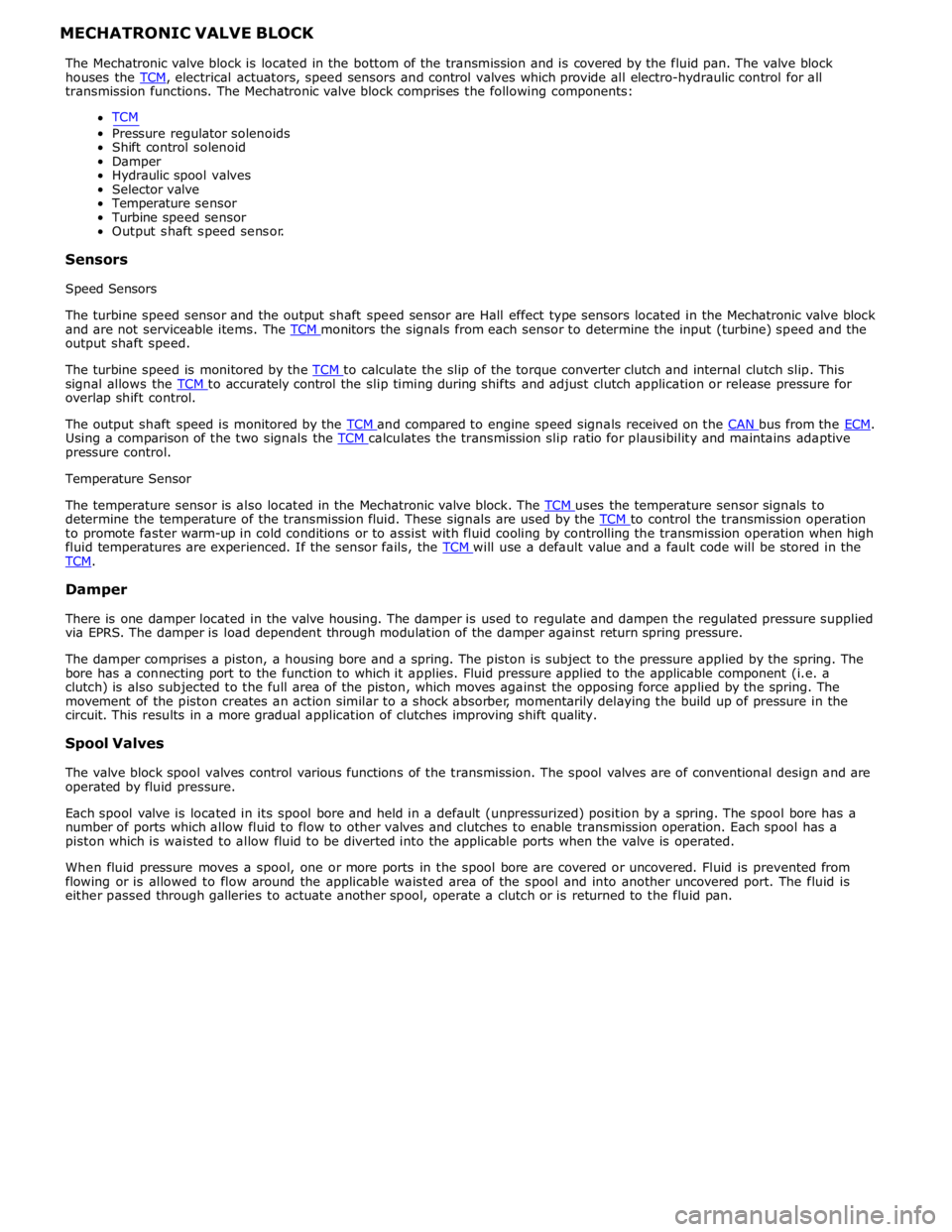
transmission functions. The Mechatronic valve block comprises the following components:
TCM
Pressure regulator solenoids
Shift control solenoid
Damper
Hydraulic spool valves
Selector valve
Temperature sensor
Turbine speed sensor
Output shaft speed sensor.
Sensors
Speed Sensors
The turbine speed sensor and the output shaft speed sensor are Hall effect type sensors located in the Mechatronic valve block
and are not serviceable items. The TCM monitors the signals from each sensor to determine the input (turbine) speed and the output shaft speed.
The turbine speed is monitored by the TCM to calculate the slip of the torque converter clutch and internal clutch slip. This signal allows the TCM to accurately control the slip timing during shifts and adjust clutch application or release pressure for overlap shift control.
The output shaft speed is monitored by the TCM and compared to engine speed signals received on the CAN bus from the ECM. Using a comparison of the two signals the TCM calculates the transmission slip ratio for plausibility and maintains adaptive pressure control.
Temperature Sensor
The temperature sensor is also located in the Mechatronic valve block. The TCM uses the temperature sensor signals to determine the temperature of the transmission fluid. These signals are used by the TCM to control the transmission operation to promote faster warm-up in cold conditions or to assist with fluid cooling by controlling the transmission operation when high
fluid temperatures are experienced. If the sensor fails, the TCM will use a default value and a fault code will be stored in the TCM.
Damper
There is one damper located in the valve housing. The damper is used to regulate and dampen the regulated pressure supplied
via EPRS. The damper is load dependent through modulation of the damper against return spring pressure.
The damper comprises a piston, a housing bore and a spring. The piston is subject to the pressure applied by the spring. The
bore has a connecting port to the function to which it applies. Fluid pressure applied to the applicable component (i.e. a
clutch) is also subjected to the full area of the piston, which moves against the opposing force applied by the spring. The
movement of the piston creates an action similar to a shock absorber, momentarily delaying the build up of pressure in the
circuit. This results in a more gradual application of clutches improving shift quality.
Spool Valves
The valve block spool valves control various functions of the transmission. The spool valves are of conventional design and are
operated by fluid pressure.
Each spool valve is located in its spool bore and held in a default (unpressurized) position by a spring. The spool bore has a
number of ports which allow fluid to flow to other valves and clutches to enable transmission operation. Each spool has a
piston which is waisted to allow fluid to be diverted into the applicable ports when the valve is operated.
When fluid pressure moves a spool, one or more ports in the spool bore are covered or uncovered. Fluid is prevented from
flowing or is allowed to flow around the applicable waisted area of the spool and into another uncovered port. The fluid is
either passed through galleries to actuate another spool, operate a clutch or is returned to the fluid pan.
Page 1434 of 3039
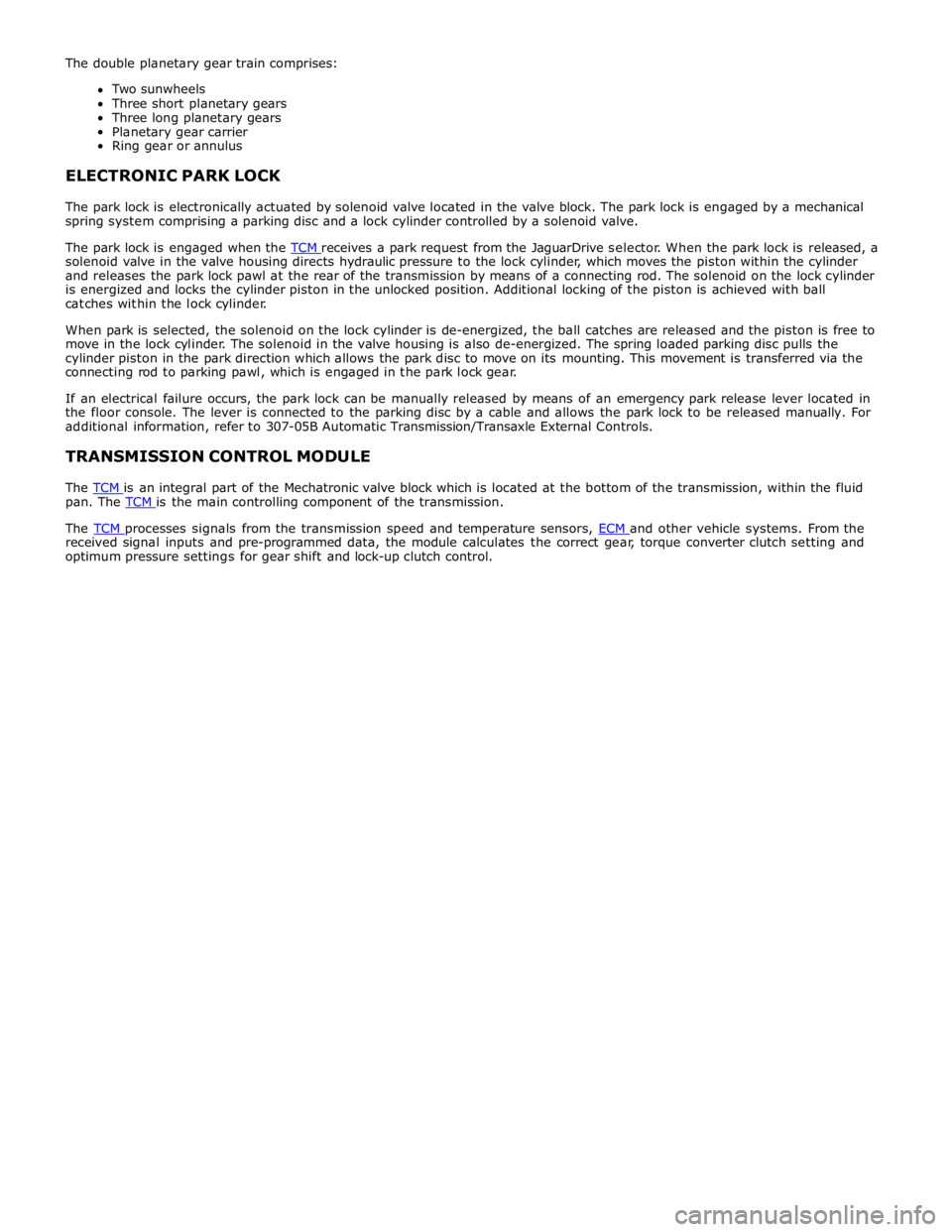
solenoid valve in the valve housing directs hydraulic pressure to the lock cylinder, which moves the piston within the cylinder
and releases the park lock pawl at the rear of the transmission by means of a connecting rod. The solenoid on the lock cylinder
is energized and locks the cylinder piston in the unlocked position. Additional locking of the piston is achieved with ball
catches within the lock cylinder.
When park is selected, the solenoid on the lock cylinder is de-energized, the ball catches are released and the piston is free to
move in the lock cylinder. The solenoid in the valve housing is also de-energized. The spring loaded parking disc pulls the
cylinder piston in the park direction which allows the park disc to move on its mounting. This movement is transferred via the
connecting rod to parking pawl, which is engaged in the park lock gear.
If an electrical failure occurs, the park lock can be manually released by means of an emergency park release lever located in
the floor console. The lever is connected to the parking disc by a cable and allows the park lock to be released manually. For
additional information, refer to 307-05B Automatic Transmission/Transaxle External Controls.
TRANSMISSION CONTROL MODULE
The TCM is an integral part of the Mechatronic valve block which is located at the bottom of the transmission, within the fluid pan. The TCM is the main controlling component of the transmission.
The TCM processes signals from the transmission speed and temperature sensors, ECM and other vehicle systems. From the received signal inputs and pre-programmed data, the module calculates the correct gear, torque converter clutch setting and
optimum pressure settings for gear shift and lock-up clutch control.