2010 JAGUAR XFR lock
[x] Cancel search: lockPage 588 of 3039

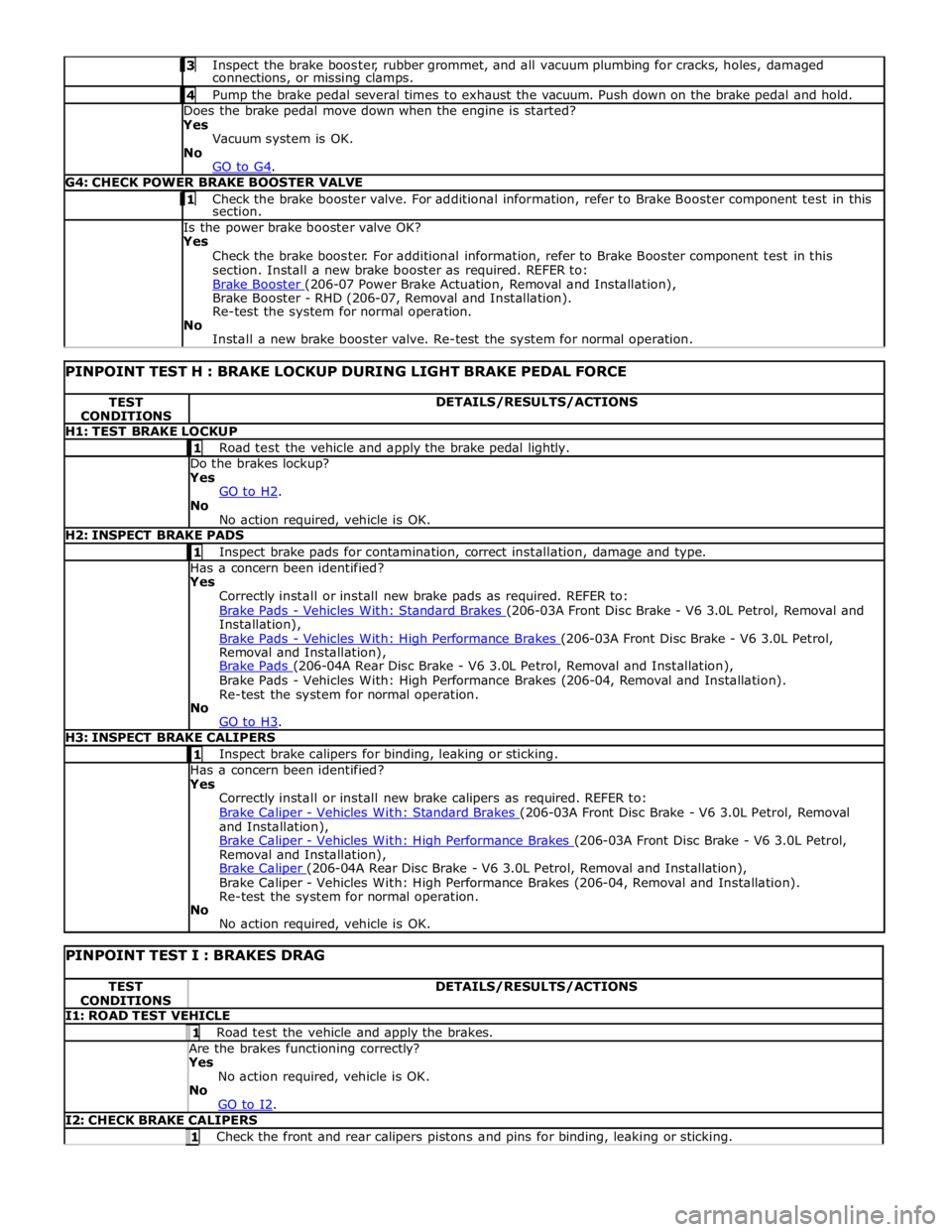
Inspect the brake booster, rubber grommet, and all vacuum plumbing for cracks, holes, damaged connections, or missing clamps. 4 Pump the brake pedal several times to exhaust the vacuum. Push down on the brake pedal and hold. Does the brake pedal move down when the engine is started?
Yes
Vacuum system is OK.
No
GO to G4. G4: CHECK POWER BRAKE BOOSTER VALVE 1 Check the brake booster valve. For additional information, refer to Brake Booster component test in this section. Is the power brake booster valve OK?
Yes
Check the brake booster. For additional information, refer to Brake Booster component test in this
section. Install a new brake booster as required. REFER to:
Brake Booster (206-07 Power Brake Actuation, Removal and Installation), Brake Booster - RHD (206-07, Removal and Installation).
Re-test the system for normal operation.
No
Install a new brake booster valve. Re-test the system for normal operation.
PINPOINT TEST H : BRAKE LOCKUP DURING LIGHT BRAKE PEDAL FORCE TEST
CONDITIONS DETAILS/RESULTS/ACTIONS H1: TEST BRAKE LOCKUP 1 Road test the vehicle and apply the brake pedal lightly. Do the brakes lockup?
Yes
GO to H2. No
No action required, vehicle is OK. H2: INSPECT BRAKE PADS 1 Inspect brake pads for contamination, correct installation, damage and type. Has a concern been identified?
Yes
Correctly install or install new brake pads as required. REFER to:
Brake Pads - Vehicles With: Standard Brakes (206-03A Front Disc Brake - V6 3.0L Petrol, Removal and Installation),
Brake Pads - Vehicles With: High Performance Brakes (206-03A Front Disc Brake - V6 3.0L Petrol, Removal and Installation),
Brake Pads (206-04A Rear Disc Brake - V6 3.0L Petrol, Removal and Installation), Brake Pads - Vehicles With: High Performance Brakes (206-04, Removal and Installation).
Re-test the system for normal operation.
No
GO to H3. H3: INSPECT BRAKE CALIPERS 1 Inspect brake calipers for binding, leaking or sticking. Has a concern been identified?
Yes
Correctly install or install new brake calipers as required. REFER to:
Brake Caliper - Vehicles With: Standard Brakes (206-03A Front Disc Brake - V6 3.0L Petrol, Removal and Installation),
Brake Caliper - Vehicles With: High Performance Brakes (206-03A Front Disc Brake - V6 3.0L Petrol, Removal and Installation),
Brake Caliper (206-04A Rear Disc Brake - V6 3.0L Petrol, Removal and Installation), Brake Caliper - Vehicles With: High Performance Brakes (206-04, Removal and Installation).
Re-test the system for normal operation.
No
No action required, vehicle is OK.
PINPOINT TEST I : BRAKES DRAG TEST
CONDITIONS DETAILS/RESULTS/ACTIONS I1: ROAD TEST VEHICLE 1 Road test the vehicle and apply the brakes. Are the brakes functioning correctly? Yes
No action required, vehicle is OK.
No
GO to I2. I2: CHECK BRAKE CALIPERS 1 Check the front and rear calipers pistons and pins for binding, leaking or sticking.
Page 590 of 3039

Does the brake pedal return to its original position? Yes
No action required, vehicle is OK.
No
GO to K2. K2: CHECK FOR BRAKE PEDAL BINDING 1 Disconnect the brake booster from the brake pedal. Check the brake pedal to ensure free operation. Is the brake pedal operating freely? Yes
Install a new brake booster as required. REFER to:
Brake Booster (206-07 Power Brake Actuation, Removal and Installation), Brake Booster - RHD (206-07, Removal and Installation).
Re-test the system for normal operation.
No
Repair or install new brake pedal. Re-test the system for normal operation. Component Tests
Brake Booster
1. Check all hoses and connections. All unused vacuum connectors should be capped. Hoses and their connections should
be correctly secured and in good condition with no holes and no collapsed areas. Inspect the valve on the brake booster
for damage.
2. Check the hydraulic brake system for leaks or low fluid.
3. With the automatic transmission in PARK, stop the engine and apply the parking brake. Pump the brake pedal several
times to exhaust all vacuum in the system. With the engine switched off and all vacuum in the system exhausted,
apply the brake pedal and hold it down. Start the engine. If the vacuum system is operating, the brake pedal will tend
to move downward under constant foot pressure. If no motion is felt, the vacuum booster system is not functioning.
4. Remove the vacuum hose from the brake booster. Manifold vacuum should be available at the brake booster end of the
hose with the engine at idle speed and the automatic transmission in PARK. Make sure that all unused vacuum outlets
are correctly capped, hose connectors are correctly secured and vacuum hoses are in good condition. When it is
established that manifold vacuum is available to the brake booster, connect the vacuum hose to the brake booster and
repeat Step 3. If no downward movement of the brake pedal is felt, install a new brake booster.
5. Operate the engine for a minimum of 10 seconds at a fast idle. Stop the engine and allow the vehicle to stand for 10
minutes. Then, apply the brake pedal with approximately 89 N (20lb) of force. The pedal feel (brake application) should
be the same as that noted with the engine running. If the brake pedal feels hard (no power assist), install a new valve
and then repeat the test. If the brake pedal still feels hard, install a new brake booster. If the brake pedal movement
feels spongy, bleed the brake system.
REFER to: Brake System Bleeding (206-00 Brake System - General Information, General Procedures). Brake Master Cylinder
Usually, the first and strongest indicator of anything wrong in the brake system is a feeling through the brake pedal. In
diagnosing the condition of the brake master cylinder, check pedal feel as evidence of a brake concern. Check for brake warning
lamp illumination and the brake fluid level in the brake master cylinder reservoir.
Normal Conditions
The following conditions are considered normal and are not indications that the brake master cylinder is in need of repair.
Modern brake systems are designed to produce a pedal effort that is not as hard as in the past. Complaints of light
pedal efforts should be compared to the pedal efforts of another vehicle of the same model and year.
The fluid level will fall with brake pad wear.
Abnormal Conditions
Changes in the brake pedal feel or brake pedal travel are indicators that something could be wrong in the brake system. The
diagnostic procedure and techniques use brake pedal feel, warning indicator illumination and low brake fluid level as indicators
to diagnosing brake system concerns. The following conditions are considered abnormal and indicate that the brake master
cylinder is in need of repair:
NOTE: Prior to carrying out any diagnosis, make sure the brake system warning indicator is functional.
Brake pedal goes down fast. This could be caused by an external or internal leak.
Brake pedal goes down slowly. This could be caused by an internal or external leak.
Brake pedal is low or feels spongy. This condition may be caused by no fluid in the brake master cylinder, reservoir cap
vent holes clogged or air in the hydraulic system.
Brake pedal effort is excessive. This may be caused by a bind or obstruction in the pedal/linkage, a faulty non-return
valve, booster or insufficient booster vacuum.
Rear brakes lock up during light pedal force. This may be caused by damaged brake pads, a partially applied parking
brake, a damaged ABS sensor or bearing failure.
Brake pedal effort erratic. This condition could be caused by the brake booster or incorrectly installed brake pads.
Brake warning indicator is on. This may be caused by low fluid level or float assembly damaged. www.JagDocs.com
Page 616 of 3039

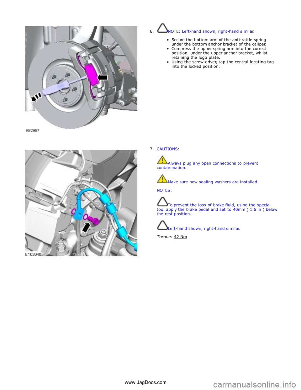
6. NOTE: Left-hand shown, right-hand similar.
Secure the bottom arm of the anti-rattle spring
under the bottom anchor bracket of the caliper.
Compress the upper spring arm into the correct
position, under the upper anchor bracket, whilst
retaining the logo plate.
Using the screw-driver, tap the central locating tag
into the locked position.
7. CAUTIONS:
Always plug any open connections to prevent
contamination.
Make sure new sealing washers are installed.
NOTES:
To prevent the loss of brake fluid, using the special
tool apply the brake pedal and set to 40mm ( 1.6 in ) below
the rest position.
Left-hand shown, right-hand similar.
Torque: 42 Nm www.JagDocs.com
Page 624 of 3039

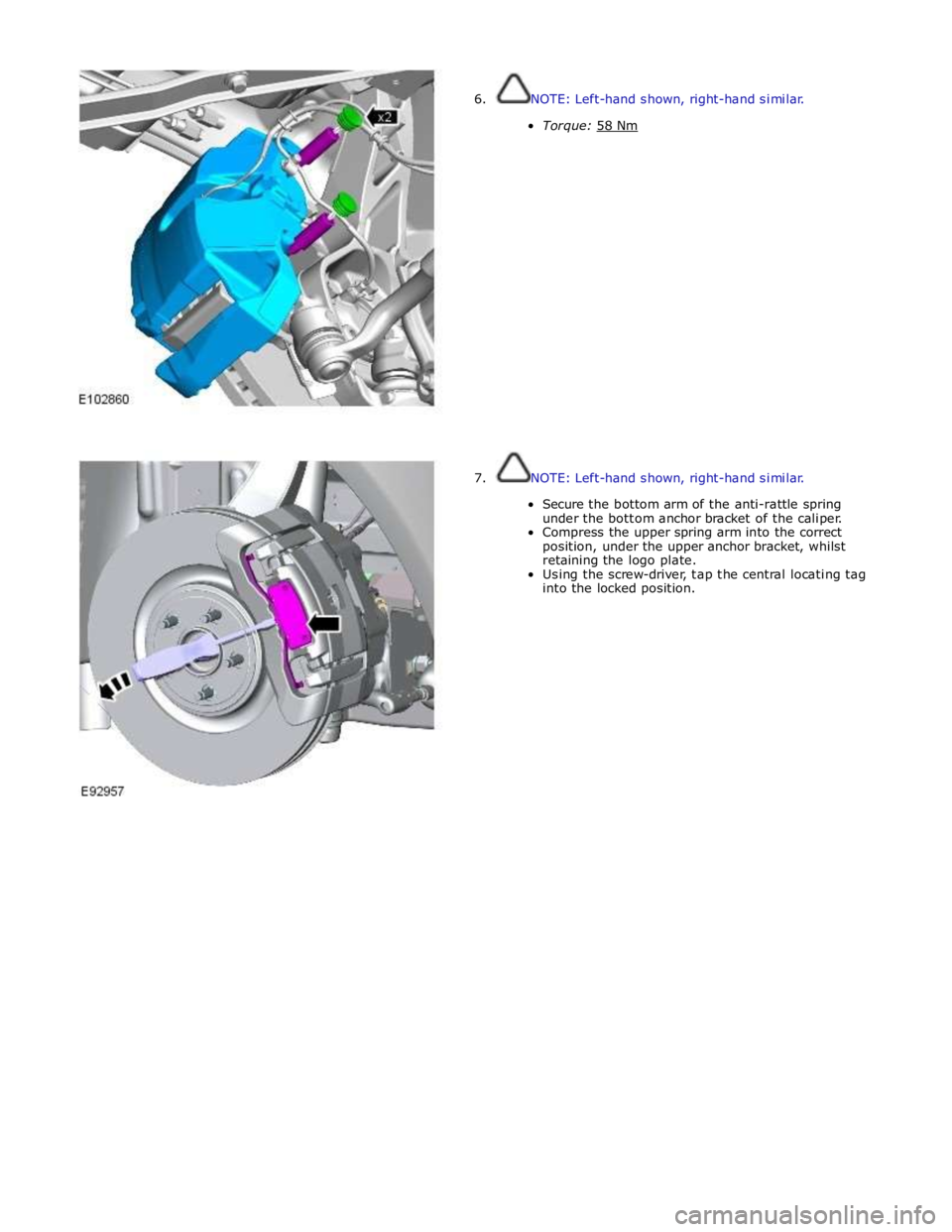
7. NOTE: Left-hand shown, right-hand similar.
Secure the bottom arm of the anti-rattle spring
under the bottom anchor bracket of the caliper.
Compress the upper spring arm into the correct
position, under the upper anchor bracket, whilst
retaining the logo plate.
Using the screw-driver, tap the central locating tag
into the locked position.
Page 648 of 3039

7 Instrument cluster 8 Parking brake switch 9 Parking brake actuator
Static Apply System Operation
The EPB module receives a vehicle speed signal from the ABS (anti-lock brake system) module on the high speed CAN bus. If the parking brake switch is pulled to the 'Apply' position and vehicle speed is less than 2 mph (3 km/h), the EPB module will
instigate its 'Static Apply' mode and drive the actuator to apply full parking brake force to the rear wheels.
The EPB module monitors the current drawn by the actuator and compares this to information held within its configuration
software to determine when full braking force has been applied.
Dynamic Apply
There are two 'Dynamic Apply' modes; low speed dynamic and high speed dynamic. The low speed dynamic mode operates at
speeds between 2 mph (3 km/h) and 20 mph (32 km/h). The high speed dynamic mode operates at speeds above 20 mph (32
km/h).
If the parking brake switch is pulled up to the 'Apply' position and vehicle speed is within the low speed dynamic range, the
EPB module drives the actuator to apply full parking brake force to the rear wheels.
If the parking brake switch is pulled up to the 'Apply' position and vehicle speed is within the high speed dynamic range, the
EPB module will apply braking force to the rear wheels at a slower rate until full braking load is reached or the switch is
released. The rate with which braking force is applied is controlled by the EPB module, which monitors both current drawn by
the actuator and positional information from the actuator hall sensor and compares this to information held within its
configuration software.
Drive Away Release
The EPB module will initiate its 'Drive Away Release' function and automatically release the parking brake if the following
conditions are detected:
The engine is running.
Drive , or reverse is selected.
Positive throttle movement is detected.
The EPB module receives messages of gear selector position and throttle angle over the high speed CAN bus from the TCM (transmission control module) and the ECM (engine control module) respectively.
Release from Park
The EPB module will initiate its 'Release from Park' function and automatically release the parking brake if the gear selector is
moved from Park to any position except Neutral.
Repairs
Before carrying out any work on the parking brake system, the Jaguar approved diagnostic system must be connected and the
'parking brake unjam' routine run. The routine can be found in the 'Vehicle Configuration' area, under the 'Set-up and
Configuration' menu. After any work has been carried out on the parking brake, the system will require resetting.
CAUTION: Do not use the 'Emergency Release' tool to allow work to be carried out on the parking brake. Work can only be
carried out on the parking brake system after the 'parking brake unjam' routine has been run.
Resetting
If the electrical supply is disconnected from the EPB module, the actuator will loose its position memory. On battery
re-connection and ignition on, 'APPLY FOOT AND PARK BRAKE' will be displayed in the instrument cluster message center
indicating the parking brake requires resetting.
Refer to: Parking Brake (206-05, Diagnosis and Testing).
Operating Voltages
The EPB module will only operate the actuator if the power supply from the battery is between 9 V and 16 V. At any voltage
within this range, the actuator is able to fully tighten and release the brake cables. If the power supply falls outside of the
range, a fault code is stored in the EPB module and can be retrieved using the Jaguar approved diagnostic system.
Page 651 of 3039

Stoplamp Switch
The stoplamp switch is mounted on the brake pedal box. One of the prerequisites for releasing the parking brake is that the
foot brake is applied. The EPB module is able to determine the position of the footbrake by monitoring the status of the
stoplamp switch via a hardwired electrical connection.
The stoplamp switch also forms part of:
The ABS. Refer to: Anti-Lock Control - Stability Assist (206-09 Anti-Lock Control - Stability Assist, Description and Operation). The speed control system. For additional information, refer to:
Speed Control (310-03A, Description and Operation),
Speed Control (310-03B, Description and Operation),
Speed Control (310-03C, Description and Operation).
Page 668 of 3039

Published: 11-May-2011
Hydraulic Brake Actuation - Hydraulic Brake Actuation - Component Location
Description and Operation
NOTE: RHD (right-hand drive) installation shown, LHD (left-hand drive) installation similar.
Component Location
Item Description 1 Brake master cylinder and fluid reservoir 2 Brake pedal 3 Brake pipes 4 Stoplamp switch 5 ABS (anti-lock brake system) module/ HCU (hydraulic control unit) 6 Brake booster
Page 670 of 3039

Refer to: Anti-Lock Control - Stability Assist (206-09 Anti-Lock Control - Stability Assist, Description and Operation). www.JagDocs.com