2010 JAGUAR XFR light
[x] Cancel search: lightPage 1829 of 3039
module and fuel injector operating data from the ECM.
A 'Trip' button is located on the end of the LH (left-hand) multifunction switch and allows the driver to access, in sequence, the
available trip information by repeatedly pressing the button. The trip information is displayed in the following order:
Trip distance – The trip distance since the last reset is displayed
Average speed – The average speed since the last reset is displayed
Average fuel consumption – The average fuel consumption since the last reset is displayed
Range – The range is displayed showing the distance which can be travelled until the fuel gage reads empty. If the
range display shows dashes (-), this indicates a failure with one or both of the fuel level sensors.
The trip computer has three independent memories; A, B and Auto. Memories A and B can be set independently. The Auto
memory is reset after each ignition cycle and therefore only contains information relating the current journey.
The trip information can also be accessed from the TSD located in the center console. The TSD allows the same information
available with the trip button on the multifunction switch to be displayed on the TSD, with the addition of the option to reset
the values in the A and B memories.
If the battery is disconnected, all trip data in memories A, B and Auto are erased.
Fuel Level Display
The fuel level display is a linear LCD display to show the usable fuel tank contents. The level display is active at all times when the ignition is on. Low fuel level is displayed as a LOW FUEL LEVEL message and an amber warning triangle in the
message center.
The fuel level is obtained by fuel level sensors in the fuel tank. These are monitored by the RJB software and their output resistance values, corresponding fuel quantity, are transmitted to the instrument cluster on the medium speed CAN bus. The instrument cluster uses the two level sensor signals to calculate the fuel tank contents. This calculation takes into account
fuel movement in the tank to display a steady fuel quantity in the LCD.
The fuel level information is transmitted on the medium speed and high speed CAN bus for use by other vehicle system modules.
AUDIBLE WARNINGS
The instrument cluster can generate audible warnings to alert the driver to a displayed message and change of vehicle
operating condition. The audible warning is generated by a sounder located within the instrument cluster. The audible warnings
can be generated for the warnings below and are listed in order of priority, with the first being the highest priority:
Seatbelt reminder
EPB (High Pitch)
ACC Driver Intervene 1
Airbag fault
Key in ignition switch
ASL overspeed
ACC Driver Intervene 2
EPB (Low Pitch)
Vehicle armed (entry delay)
JaguarDrive selector not in park
Valet mode
Lights on reminder
Hood operation
Passive Entry / Passive Start (PEPS)
Memory set
Turn signal indicators
Seat Belt Minder.
The audible warnings can take the form of a single chime, a number of chimes or a continuous chime. The audible warnings are
initiated by a CAN message request from the requesting sub-system control module or by the instrument cluster software.
Page 1832 of 3039
Warning Devices - Blindspot Monitoring System - Overview
Description and Operation
OVERVIEW Published: 11-May-2011
Eliminating blind spots is a major element in vehicle body design, but because of the structural requirements of B, C and D
posts, blind spots cannot be entirely eliminated. Statistics show that some accidents are directly attributable to drivers moving
across into the path of overtaking vehicles that have not been seen in conventional mirrors. New mirror designs have improved
the situation, but by remotely covering areas that cannot be seen either directly or by the vehicle mirrors, have led to the
introduction of a radar-based blind spot monitoring system.
The blind spot monitoring system comprises:
LH (left-hand) Blind spot monitoring sensor
RH (right-hand) Blind spot monitoring sensor
LH door mirror RH door mirror
The system uses two radar modules operating at a frequency of 24 GHz and each combining the radar face and electronic
module in a single unit. The modules are located behind the rear bumper surface, symmetrically, one on each side of the car
behind the rear wheels. They are side facing and inclined rearwards at an angle of 16 degrees, which is dictated by the shape
at the rear of the vehicle. Each module is calibrated to detect a vehicle in the driver’s blind spot. Once a vehicle is detected
the module illuminates an amber warning ‘alert icon’ LED (light emitting diode) in the relevant exterior door mirror. If there is a
fault or blockage with the blind spot monitoring system an amber warning indicator dot LED is displayed in the exterior mirror and the message ‘blind spot monitoring not available’ is displayed in the instrument cluster message center.
When the system initiates, it performs a self-check, during which the warning icons in the mirrors illuminate alternately for a
short period of time. Each module does a left/right determination check when the ignition is switched on. Each mirror has a
different circuit configuration so that the modules can determine which mirror they are connected to. If a module detects the
wrong mirror it will go into a fault condition.
The blind spot monitoring modules receive vehicle speed on the medium speed CAN (controller area network) and are inactive
until the vehicle reaches 16kph (10mph). Each blind spot monitor module emits a radar field greater than the blind spot area.
Each Blind Spot Monitor module emits a radar field greater than the blind spot area. The actual blind spot area is calibrated
into the module during its manufacture.
CAUTION: The blind spot monitoring system is designed as a driver aid not a safety device. The driver should always
exercise due care and attention whilst driving. www.JagDocs.com
Page 1834 of 3039
Blind Spot Monitoring System Operation
The purpose of the blind spot monitoring system is to detect an object moving with a positive velocity relative to the radar
module, on either side of the vehicle, at a distance of up to 2.5 meters laterally and in an area from the door mirror up to 7.0
meters behind the module. These criteria identify an overtaking vehicle within the blind-spot area and within a typical
carriageway lane width, while eliminating other objects that are not relevant, either because of their position, they are
stationary, traveling in the opposite direction, or being overtaken. A vehicle is classed as a heavy goods vehicle, car or
motorcycle. A motorcycle is defined as a minimum size of 2.0m long, 0.8m wide (widest point) and 1.1m high. The system is
not affected by the mass of the overtaking vehicle providing all identification criteria, including relative velocity of (16km/h -
10mph) or above, is met.
The system emits radar pulses and analyses the reflections, identifying anything that moves into the blind spot zone. Having
detected another vehicle in the defined blind spot zone it alerts the driver by illuminating the amber alert icon located in the
appropriate exterior mirror.
NOTE: If an overtaking vehicle is detected on both sides of the vehicle simultaneously, the warning alert icons in both
mirrors will illuminate.
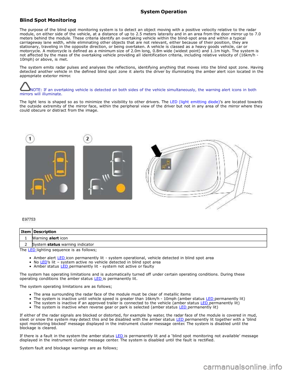
The light lens is shaped so as to minimize the visibility to other drivers. The LED (light emitting diode)’s are located towards
the outside extremity of the mirror face, within the peripheral view of the driver but not in any area of the mirror where they
could obscure or distract from the image.
Item Description 1 Warning alert icon 2 System status warning indicator The LED lighting sequence is as follows;
Amber alert LED icon permanently lit - system operational, vehicle detected in blind spot area No LED’s lit – system active no vehicle detected in blind spot area Amber status LED permanently lit - system not active or faulty
The system has operating limitations and is automatically turned off under certain operating conditions. During these
operating conditions the amber status LED is permanently lit. The system operating limitations are as follows;
The area surrounding the radar face of the module must be clear of metallic items
The system is inactive until vehicle speed is greater than 16km/h - 10mph (amber status LED permanently lit) The system is inactive if an approved trailer is connected to the vehicle (amber status LED permanently lit) The system is inactive when reverse gear or park is selected (amber status LED permanently lit)
If either of the radar signals are blocked or distorted, for example by water, the radar face of the module is covered in mud,
sleet or snow the system may detect this and be disabled with the amber status LED permanently lit together with a ‘blind spot monitoring blocked’ message displayed in the instrument cluster message center. The system is disabled until the
blockage is cleared.
If there is a fault in the system the amber status LED is permanently lit and a ‘blind spot monitoring not available’ message displayed in the instrument cluster message center. The system is disabled until the fault is rectified.
System fault and blockage warnings are as follows;
Page 1845 of 3039
3 RJB 4 Entertainment system control module 5 Touch Screen Display (TSD) 6 Parking aid camera
PARKING AID System Operation
Two levels of parking aid system can be fitted; a rear only system or a front and rear system.
The parking aid module receives and ignition power mode 6 supply from the RJB. The parking aid module is connected to the entertainment system control module by the medium speed CAN (controller area
network) bus and the Media Orientated System Transport (MOST). The entertainment system is used by the parking aid system
to provide the driver with an audible warning. If an obstacle is sensed by the rear parking aid sensors, the rear audio system
speakers will sound. If an obstacle is sensed by the front parking aid sensors (if fitted), the front audio system speakers will
sound.
The parking aid system operates using ultrasonic signals which are transmitted by the sensors. The reflected echo from this
output is received by the sensors and used by the parking aid module to calculate the distance from an object.
When the parking aid module activates the system, the switch LED (light emitting diode) is illuminated to indicate that the
system is operating. The parking aid module then processes signals received from the sensors to determine if there is an
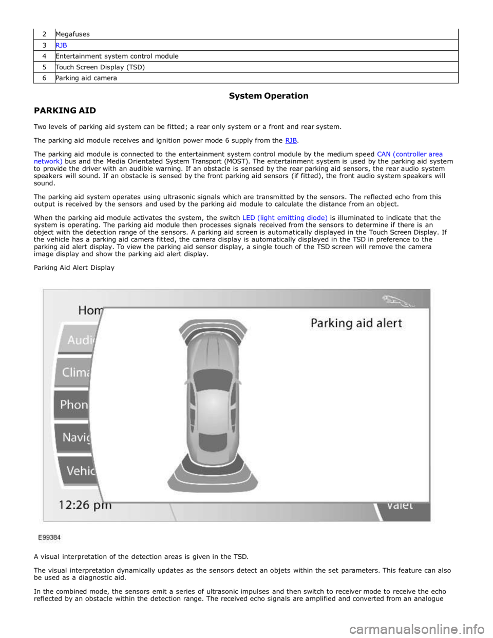
object with the detection range of the sensors. A parking aid screen is automatically displayed in the Touch Screen Display. If
the vehicle has a parking aid camera fitted, the camera display is automatically displayed in the TSD in preference to the
parking aid alert display. To view the parking aid sensor display, a single touch of the TSD screen will remove the camera
image display and show the parking aid alert display.
Parking Aid Alert Display
A visual interpretation of the detection areas is given in the TSD.
The visual interpretation dynamically updates as the sensors detect an objets within the set parameters. This feature can also
be used as a diagnostic aid.
In the combined mode, the sensors emit a series of ultrasonic impulses and then switch to receiver mode to receive the echo
reflected by an obstacle within the detection range. The received echo signals are amplified and converted from an analogue
Page 1852 of 3039

Symptom Possible Causes Action Parking aid sensors are being
returned with no faults found
or signs of water
ingress/corrosion Possible issue with sensor connectors
not latched correctly
When either no/intermittent operation has been
reported the following action should be taken
1. Using Datalogger, identify the position of the
suspect parking aid sensor within the bumper
2. Visually locate the position of the suspect
parking aid sensor. Inspect and provide details in
claim if the sensor has any sign of physical
damage
3. Remove the bumper. Disconnect the wiring at
the main harness connector. Inspect the main
harness connectors and terminals for signs of
damage, backed out pins, corrosion and water
ingress, or damage to the seals. Provide details in
claim if any of the above symptoms are present
4. Attempt to remove the harness connector from
the suspect parking aid sensor without using the
connector latch i.e. lightly pull back on ALL wires
together, ensuring the harness is held close to the
back of the connector, not elsewhere on the wiring
harness. DO NOT apply excessive force. If the
connector can be removed without using the latch,
provide details in claim if connector is loose. If the
connector is fully latched, disconnect it from the
sensor
5. Inspect and provide details in claim if the
suspect sensor harness connector has any sign of
water ingress/corrosion
6. Inspect and provide details in claim if the
suspect parking aid sensor harness connector
shows any sign that the terminals have backed-out
of the connector or for any damage to the terminal
seals. Replace/repair the harness as required and
proceed
7. Remove the suspect parking aid sensor from the
bumper. Inspect the parking aid sensor connector
for signs of water ingress/corrosion. Provide details
in claim if corrosion/water ingress is present
8. Exchange the suspect parking aid sensor with
another parking aid sensor within the bumper that
is performing correctly. Reconnect all sensors and
reconnect the bumper main harness connector.
Repeat step 1. Confirm if the original fault now
appears at the new position of the suspect parking
aid sensor, if so, proceed to step 10
9. If not, carry out the appropriate open circuit and
short circuit checks between the original suspect
parking aid sensor harness connector and the
parking aid control module
10. Refit the parking aid sensors to their original
position in the bumper
11. Reconnect the parking aid sensor to the
bumper harness connector. Reconnect main harness
connector and refit the bumper
12. Repeat Step 1. If fault is still present, replace
only the faulty sensor
PINPOINT TEST A : PARKING AID SYSTEM NOT FUNCTIONING CORRECTLY WITH NO DTCS LOGGED TEST
CONDITIONS DETAILS/RESULTS/ACTIONS A1: PERMANENT FAULT 1 When the parking aid system is activated, there is a vibration on the parking aid sensor membrane. This can be verified by touching the parking aid sensor face with a hard item such as a pencil, ball-pen, small
screwdriver, or fingernail. Ensure no damage is caused to sensor painted surface Are the parking aid sensor(s) vibrating? Yes
GO to A2. No
GO to A5. A2: SENSORS VIBRATING WITH PARKING AID FAULT 1 Clean the parking aid sensor face Parking aid system functioning correctly? Yes
No further action required
No www.JagDocs.com
Page 1854 of 3039
PINPOINT TEST B : PARKING AID SYSTEM NOT FUNCTIONING CORRECTLY WITH NO DTCS LOGGED TEST
CONDITIONS DETAILS/RESULTS/ACTIONS B1: PARKING AID SYSTEM GIVES WARNING SIGNAL WITHOUT OBSTACLE 1 Clean the parking aid sensor face. Check for any damage to the parking aid sensor face. Rectify as required. Snow, water or ice on sensor face. Parking aid sensor face has been repainted to the incorrect
thickness. Rectify as required Parking aid system functioning correctly? Yes
No further action required
No
GO to B2. B2: PARKING AID SYSTEM GIVES WARNING SIGNAL WITHOUT OBSTACLE 1 Ensure the vehicle ride height is within manufacturer specified limits. Rectify as required Parking aid system functioning correctly? Yes
No further action required
No
GO to B3. B3: PARKING AID SYSTEM GIVES WARNING SIGNAL WITHOUT OBSTACLE 1 Check for any non standard accessories are not fitted, such as tow bar, bike rack, body kit, modified exhaust, lighting or licence plate holder Parking aid system functioning correctly? Yes
No further action required
No
GO to B4. B4: PARKING AID SYSTEM GIVES WARNING SIGNAL WITHOUT OBSTACLE 1 Limitations or characteristics of the parking aid system such as vehicle on a gradient, exhaust gas vapour, signal reflection Parking aid system functioning correctly? Yes
No further action required
No
For a detailed description of the parking aid system, refer to the relevant description and operation
section in the workshop manual.
REFER to: Parking Aid (413-13 Parking Aid, Description and Operation). DTC Index
CAUTION: Diagnosis by substitution from a donor vehicle is NOT acceptable. Substitution of control modules does not
guarantee confirmation of a fault, and may also cause additional faults in the vehicle being tested and/or the donor vehicle.
NOTES:
If the control module is suspect and the vehicle remains under manufacturer warranty, refer to the Warranty Policy and
Procedures manual (section B1.2), or determine if any prior approval programme is in operation, prior to the installation of a
new module.
Generic scan tools may not read the codes listed, or may read only five digit codes. Match the five digits from the scan
tool to the first five digits of the seven digit code listed to identify the fault (the last two digits give additional information
read by the manufacturer approved diagnostic system).
When performing voltage or resistance tests, always use a digital multimeter (DMM) accurate to three decimal places,
and with an up-to-date calibration certificate. When testing resistance always take the resistance of the DMM leads into
account.
Check and rectify basic faults before beginning diagnostic routines involving pinpoint tests.
Inspect connectors for signs of water ingress, and pins for damage and/or corrosion.
If DTCs are recorded and, after performing the pinpoint tests, a fault is not present, an intermittent concern may be the
cause. Always check for loose connections and corroded terminals. Parking aid system functioning correctly
Yes
No further action required
Page 1867 of 3039
procedure.
NOTE: Under no circumstances should the battery be disconnected with the engine running because under these
conditions the generator can give a very high output voltage. This high transient voltage will damage the electronic
components in the vehicle. Loose or incomplete battery connections may also cause high transient voltage.
3. HEALTH AND SAFETY PRECAUTIONS
WARNINGS:
BATTERY CELLS CONTAIN SULPHURIC ACID AND EXPLOSIVE MIXTURES OF HYDROGEN AND OXYGEN GASES. IT IS
THEREFORE ESSENTIAL THAT THE FOLLOWING SAFETY PRECAUTIONS ARE OBSERVED.
Batteries emit highly explosive hydrogen at all times, particularly during charging. To prevent any potential form of
ignition occurring when working in the vicinity of a battery:
Do not smoke when working near batteries.
Avoid sparks, short circuits or other sources of ignition in the battery vicinity.
Switch off current before making or breaking electrical connections.
Ensure battery charging area is well ventilated.
Ensure the charger is switched off when: a) connecting to a battery; b) disconnecting from the battery.
Always disconnect the ground cable from the battery terminal first and reconnect it last.
Batteries contain poisonous and highly corrosive acid. To prevent personal injury, or damage to clothing or the vehicle,
the following working practices should be followed when topping up, checking electrolyte specific gravity, removal, refitting or
carrying batteries:
Always wear suitable protective clothing (an apron or similar), safety glasses, a face mask and suitable gloves.
If acid is spilled or splashed onto clothing or the body, it must be neutralized immediately and then rinsed with clean
water. A solution of baking soda or household ammonia and water may be used as a neutralizer.
In the event of contact with the skin, drench the affected area with water. In the case of contact with the eyes, bathe
the affected area with cool clean water for approximately 15 minutes and seek urgent medical attention.
If battery acid is spilled or splashed on any surface of a vehicle, it should be neutralized and rinsed with clean water.
Heat is generated when acid is mixed with water. If it becomes necessary to prepare electrolyte of a desired specific
gravity, SLOWLY pour the concentrated acid into water (not water into acid), adding small amounts of acid while
stirring. Allow the electrolyte to cool if noticeable heat develops. With the exception of lead or lead-lined containers,
always use non-metallic receptacles or funnels. Do not store acid in excessively warm locations or in direct sunlight.
Due to their hazardous contents, the disposal of batteries is strictly controlled. When a battery is scrapped, ensure it is
disposed of safely, complying with local environmental regulations. If in doubt, contact your local authority for advice on
disposal facilities.
4. BATTERY CARE REQUIREMENTS
4.1 RECEIPT OF A NEW VEHICLE
Within 24 hours of receipt of a new vehicle, a battery condition check must be carried out in accordance with the battery test
process utilizing a JLR approved tester as outlined in the Equipment section (Section 5) of this procedure.
NOTE: The Midtronics code from the tester must be recorded on the form.
Any actions must be carried out in accordance with the table shown in the Determining Battery Condition section (Section 6)
of this procedure. The details must be recorded on the New Vehicle Storage Form which is part of the new vehicle storage
document.
For additional information, refer to: New Vehicle Storage Form (100-11 Vehicle Transportation Aids and Vehicle Storage, Description and Operation).
4.2 NEW VEHICLE STORAGE
If the vehicle is to be stored the transit relays MUST be refitted and / or the vehicle put into transport mode.
Transit relay removal / vehicle placed in normal mode should only be completed a maximum of 72 hours prior to handover to
customer
For vehicles without either a transit mode or transit relay the battery negative cable must be DISCONNECTED from the battery.
The battery must be tested and/or re-charged every 30 days and MUST be re-charged after every 90 day period.
NOTE: The Midtronics code from the tester must be recorded on the form. www.JagDocs.com
Page 1868 of 3039
Any actions must be carried out in accordance with the table shown in the Determining Battery Condition section (Section 6)
of this procedure. The details must be recorded on the New Vehicle Storage Form which is part of the new vehicle storage
document.
For additional information, refer to: New Vehicle Storage Form (100-11 Vehicle Transportation Aids and Vehicle Storage, Description and Operation).
4.3 PDI / DELIVERY TO CUSTOMER
Before the vehicle is handed over to the customer and as part of the PDI, the condition of the battery needs to be confirmed.
The battery condition must be checked in accordance with the battery test process utilizing a JLR approved tester as outlined
in the Equipment section (Section 5) of this procedure.
NOTE: The Midtronics code from the tester must be recorded on the form.
Any actions must be carried out in accordance with the table shown in the Determining Battery Condition section (Section 6)
of this procedure. The details must be recorded on the New Vehicle Storage Form which is part of the new vehicle storage
document.
For additional information, refer to: New Vehicle Storage Form (100-11 Vehicle Transportation Aids and Vehicle Storage, Description and Operation).
4.4 REPLACEMENT BATTERIES FOR SERVICE
All service replacement batteries must have the battery condition checked within 24 hours of receipt and controlled on a ‘First
In First Out’ basis to ensure batteries are not allowed to age unnecessarily.
For batteries in storage and not yet fitted to a vehicle, they must be stored in a dry environment, not in direct sunlight or
under any direct heat source. Any batteries exhibiting any forms of damage or corrosion must not be fitted to any vehicle. Any
batteries which are dropped must be scrapped, this applies even if no external damage is apparent.
The battery condition must be checked every 30 days in accordance with the battery test process utilizing a JLR approved
tester as outlined in the Equipment section (Section 5) of this procedure.
Any actions must be carried out in accordance with the table shown in the Determining Battery Condition section (Section 6)
of this procedure.The details must be recorded on the New Vehicle Storage Form which is part of the new vehicle storage
document.
For additional information, refer to: New Vehicle Storage Form (100-11 Vehicle Transportation Aids and Vehicle Storage, Description and Operation).
4.5 BATTERY MAINTENANCE
Any battery whether it is in a vehicle or a replacement part must be tested and/or re-charged every 30 days and MUST be
re-charged after every 90 day period.
4.6 BATTERY TEST PROCESS
It is recommended that this test is conducted at least 24 hours after the vehicle engine has been run or the battery charged to
avoid the need of surface charge removal. If time constraints make this unacceptable then the surface charge must be
removed.
Surface Charge Removal
A vehicle which has had its battery charged or been driven in a 24 hour period before the test, must have its surface charge
removed.
Turn on the ignition (power mode 6) but do not start the vehicle
Switch on the headlamps on high beam for a minimum 3 minutes
Switch off the headlamps
Wait a minimum of 5 minutes before recording test results for any battery measurements
Battery Test
The battery may be tested either on a bench or on the vehicle.
The battery condition must be checked in accordance with the battery test process utilizing a JLR approved tester as outlined
in the Equipment section (Section 5) of this procedure.
NOTE: The Midtronics code from the tester must be recorded on the form.
Any actions must be carried out in accordance with the table shown in the Determining Battery Condition section (Section 6)
of this procedure. The details must be recorded on the New Vehicle Storage Form which is part of the new vehicle storage
document.
For additional information, refer to: New Vehicle Storage Form (100-11 Vehicle Transportation Aids and Vehicle Storage, Description and Operation).
CAUTION: DO NOT connect the tester to any other circuit or chassis point other than the battery negative terminal.