2010 JAGUAR XFR light
[x] Cancel search: lightPage 1870 of 3039
system.
9 CONFIRMING ELECTROLYTE LEVEL
WARNINGS:
BEFORE CHECKING AND TOPPING-UP THE BATTERY ELECTROLYTE, REFER TO THE HEALTH AND SAFETY PRECAUTIONS
SECTION.
AGM TECHNOLOGY BATTERIES ARE FULLY SEALED FOR LIFE AND NO ATTEMPT SHOULD BE MADE TO CHECK OR TOP UP
THE ELECTROLYTE LEVEL.
On certain types of battery the electrolyte level may need to be checked.
Make sure the battery is of a type suitable for topping up. These types of batteries will have cell plugs visible on the
top face of the battery or a removable access panel to allow access to the cells.
On batteries with a clear or opaque case and level marks, check the electrolyte level by visual inspection of the
maximum level indicator mark on the battery casing indicating adequate level above the battery separators.
On batteries with black cases, remove the cell plugs or access panel and ensure the electrolyte level is level with the
indicator in the cell hole. A flashlight may be required to see the electrolyte level on this type of battery.
If the electrolyte level is low, top-up using distilled water.
NOTE: Maintenance free and Valve Regulated (AGM) batteries are sealed and therefore cannot be topped up.
CAUTION: DO NOT overfill.
Page 1871 of 3039

Published: 21-Dec-2012
Battery and Charging System - General Information - Quiescent Drain
Description and Operation
VEHICLE QUIESCENT CURRENT TESTING
On vehicles fitted with a Battery Monitoring System (BMS), the diagnostic routine for quiescent drain testing in the approved
Jaguar or Land Rover diagnostic system should be utilized.
If a customer complains of a vehicle battery that discharges continuously or when left for a prolonged period of time, it is
recommended that a quiescent drain test is performed as described below.
The battery drain should be measured using the approved Jaguar or Land Rover diagnostic system or a Digital Multi-Meter
(DVOM). A procedure for quiescent drain measurement using the diagnostic system is available in the Diagnosis and Testing
section of the Workshop Manual. The vehicle should be in the locked/armed state (for example vehicle alarm fully armed), all
doors, engine and luggage compartment lids are open and latched (so as to appear closed from an electrical point of view).
The test should take place after the vehicle has entered shutdown mode. The time taken for this to occur after the ignition is
switched off varies according to model (Refer to the Topix On line resource for details).
When the vehicle is armed, the effect of the security system Light Emitting Diode (LED) flashing is to cause a pulsation in the
measured current drain. In this case, either the average current should be taken (using a Digital Multi- Meter (DVOM) with an
averaging system) or the current reading taken, ignoring the brief high current peaks.
EQUIPMENT
Approved Jaguar or Land Rover diagnostic system with current probeOR Digital Multi-Meter (DVOM) with current probe.
METHOD OF MEASUREMENT
Using an Approved Jaguar or Land Rover Diagnostic System.
1. Switch off all electrical loads and ensure that the ignition is off
2. Connect the current probe to the approved Jaguar or Land Rover diagnostic system
3. Calibrate the probe
4. Install a clamp around the battery lead/junction box lead
5. Go to the Quiescent Current Testing section in this procedure
Using a digital multimeter
Do not use an in-line DVOM to measure the quiescent drain on vehicles fitted with an electronic throttle (for example XK 2006
onwards). The current exceeds the maximum amount the fuse in the DVOM is capable of handling.
1. Switch off all electrical loads and ensure that the ignition is off
2. Connect the current probe to the digital multmeter
3. Calibrate the probe
4. Install a clamp around the battery lead/junction box lead
5. Go to the Quiescent Current Testing section in this procedure
QUIESCENT CURRENT TESTING
1. Switch ignition to ‘on’ or select ignition mode in keyless vehicles and switch to ‘off’ (do not crank)
2. Remove key from ignition switch (if equipped)
3. Open and latch all doors, hood and luggage compartment lid
4. Lock the vehicle using the remote function on the remote handset. (Single lock only to avoid volumetric alarm arming)
5. Remove any other potential electrical drains such as accessories plugged into accessory sockets
6. Record the amperage readings after the shutdown period referenced in the Topix on line resource for details. Note all
cars from 10MY onwards and XK from 07MY and XF from 08MY should be less than 30mA after 30 minutes
7. Record the final reading on the battery report form
The preferred method of testing following an excessive current consumption figure is to use a current probe around individual
junction box leads to the various suspected circuits to identify a potential cause. This is in preference to the old method of
removing fuses for the following reasons:
The drain may be caused by a module remaining active and preventing the quiescent drain from reducing to normal
levels
The drain may be caused by a relay winding that is activated. Pulling the fuse can allow this to ‘reset’ and the drain will
be lost and go un-diagnosed
QUIESCENT DRAIN - TYPICAL VALUES
NOTE: The quiescent drain after the initial shutdown period should not exceed the value shown in the table.
Jaguar Quiescent Drain Values
MODEL SHUT DOWN PERIOD (minutes) TYPICAL VALUES BATTERY DRAIN (mA) XJS 3.2 60 <30 Sovereign 3.2 60 <37.3
Page 1890 of 3039
1. Turn on the ignition but do not start the vehicle
2. Switch on the headlamps on high beam for a minimum 3 minutes
3. Switch off the headlamps
4. Wait a minimum of 5 minutes before recording test results for any battery measurements
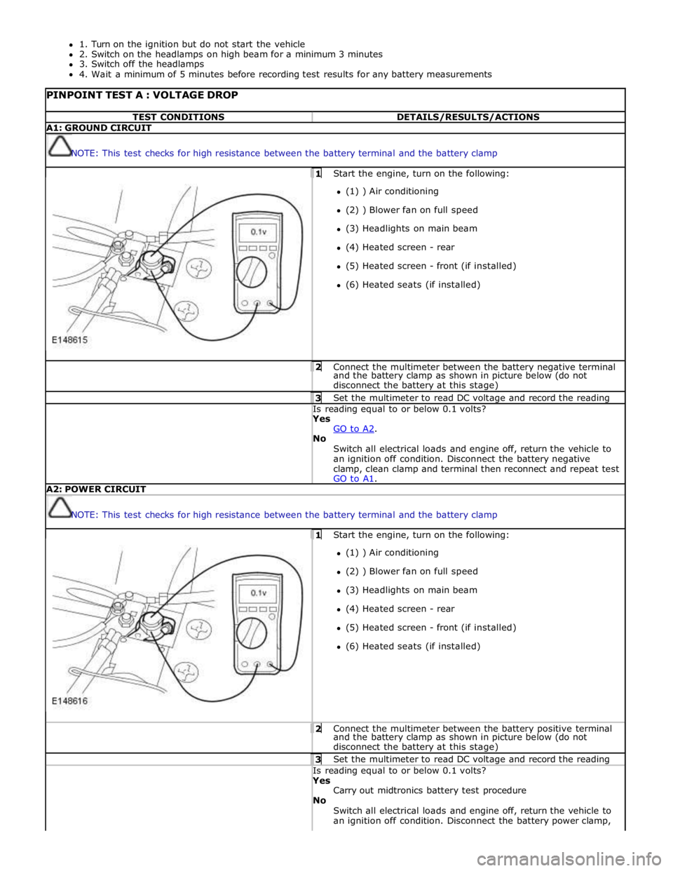
PINPOINT TEST A : VOLTAGE DROP TEST CONDITIONS DETAILS/RESULTS/ACTIONS A1: GROUND CIRCUIT
NOTE: This test checks for high resistance between the battery terminal and the battery clamp 1 Start the engine, turn on the following: (1) ) Air conditioning
(2) ) Blower fan on full speed
(3) Headlights on main beam
(4) Heated screen - rear
(5) Heated screen - front (if installed)
(6) Heated seats (if installed) 2 Connect the multimeter between the battery negative terminal and the battery clamp as shown in picture below (do not
disconnect the battery at this stage) 3 Set the multimeter to read DC voltage and record the reading Is reading equal to or below 0.1 volts? Yes
GO to A2. No
Switch all electrical loads and engine off, return the vehicle to
an ignition off condition. Disconnect the battery negative
clamp, clean clamp and terminal then reconnect and repeat test
GO to A1. A2: POWER CIRCUIT
NOTE: This test checks for high resistance between the battery terminal and the battery clamp 1 Start the engine, turn on the following: (1) ) Air conditioning
(2) ) Blower fan on full speed
(3) Headlights on main beam
(4) Heated screen - rear
(5) Heated screen - front (if installed)
(6) Heated seats (if installed) 2 Connect the multimeter between the battery positive terminal and the battery clamp as shown in picture below (do not
disconnect the battery at this stage) 3 Set the multimeter to read DC voltage and record the reading Is reading equal to or below 0.1 volts? Yes
Carry out midtronics battery test procedure
No
Switch all electrical loads and engine off, return the vehicle to
an ignition off condition. Disconnect the battery power clamp,
Page 1897 of 3039
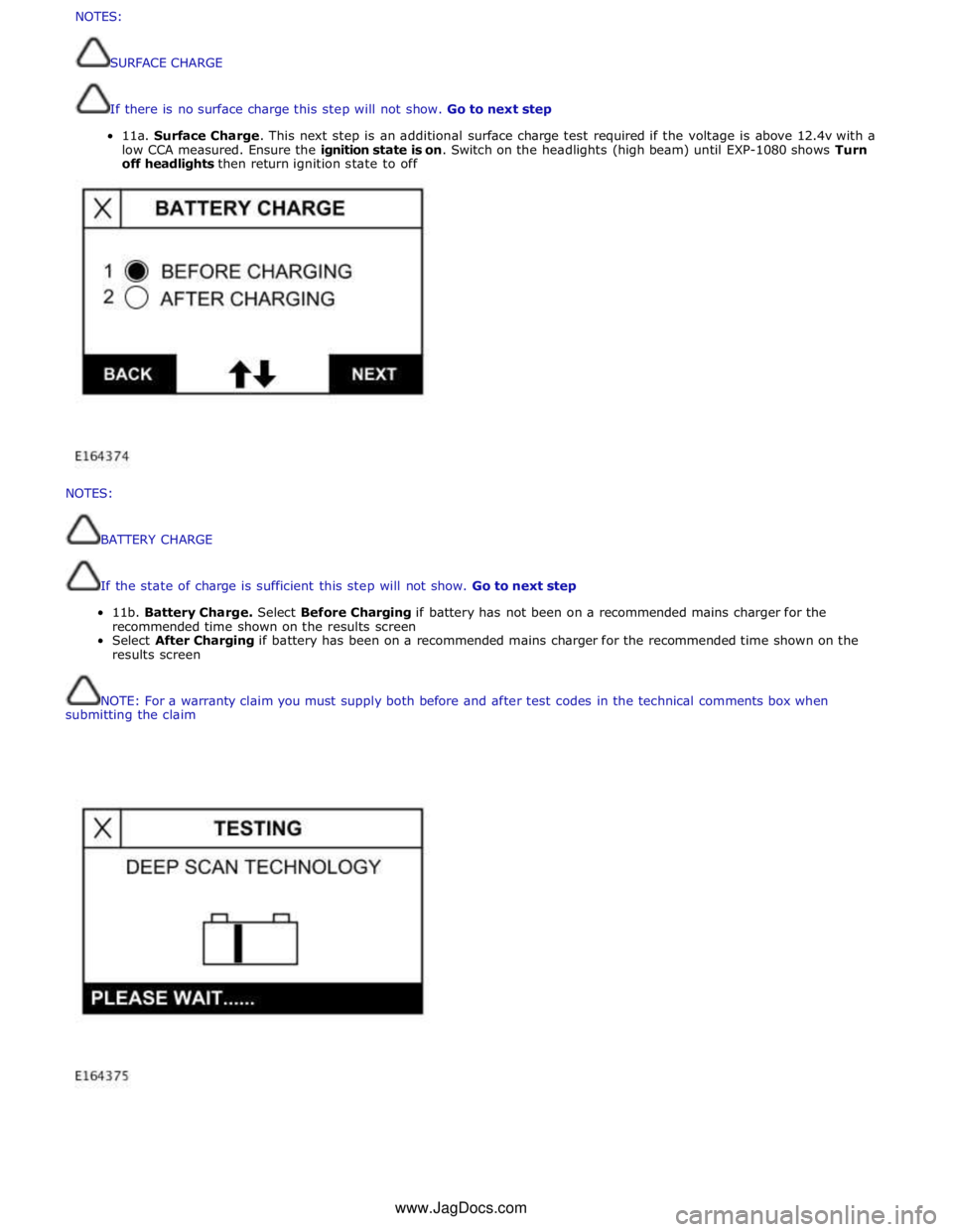
NOTES:
BATTERY
CHARGE
If
the
state
of
charge
is
sufficient
this
step
will
not
show.
Go
to
next
step
11b.
Battery
Charge.
Select
Before
Charging
if
battery
has
not
been
on
a
recommended
mains
charger
for
the
recommended
time
shown
on
the
results
screen
Select
After
Charging
if
battery
has
been
on
a
recommended
mains
charger
for
the
recommended
time
shown
on
the
results
screen
NOTE:
For
a
warranty
claim
you
must
supply
both
before
and
after
test
codes
in
the
technical
comments
box
when
submitting
the
claim
NOTES:
SURFACECHARGE
Ifthereisnosurfacechargethisstepwillnotshow.Gotonextstep
11a.SurfaceCharge.Thisnextstepisanadditionalsurfacechargetestrequiredifthevoltageisabove12.4vwith a
lowCCAmeasured.Ensuretheignitionstateis on.Switchontheheadlights(highbeam)untilEXP-1080showsTurn
offheadlightsthenreturnignitionstatetooffwww.JagDocs.com
Page 1941 of 3039
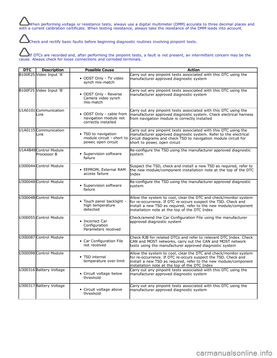
When performing voltage or resistance tests, always use a digital multimeter (DMM) accurate to three decimal places and
with a current calibration certificate. When testing resistance, always take the resistance of the DMM leads into account.
Check and rectify basic faults before beginning diagnostic routines involving pinpoint tests.
If DTCs are recorded and, after performing the pinpoint tests, a fault is not present, an intermittent concern may be the
cause. Always check for loose connections and corroded terminals.
DTC Description Possible Cause Action B100E25 Video Input 'A'
ODST Only - TV video
synch mis-match Carry out any pinpoint tests associated with this DTC using the
manufacturer approved diagnostic system B100F25 Video Input 'B'
ODST Only - Reverse
Camera video synch
mis-match Carry out any pinpoint tests associated with this DTC using the
manufacturer approved diagnostic system U1A0101
Communication
Link
ODST Only - cable from
navigation module not
correctly installed Carry out any pinpoint tests associated with this DTC using the
manufacturer approved diagnostic system. Check electrical harness
from navigation module is correctly installed U1A0115
Communication
Link
TSD to navigation
module circuit - short to
power, open circuit Carry out any pinpoint tests associated with this DTC using the
manufacturer approved diagnostic system. Refer to the electrical
circuit diagrams and check TSD to navigation module circuit for
short to power, open circuit U1A4B48
Control Module
Processor B
Supervision software
failure Re-configure the TSD using the manufacturer approved diagnostic
system U300044 Control Module
EEPROM, External RAM
access failure Suspect the TSD, check and install a new TSD as required, refer to
the new module/component installation note at the top of the DTC
Index U300048 Control Module
Supervision software
failure Re-configure the TSD using the manufacturer approved diagnostic
system U30004B Control Module
Touch panel backlight -
high temperature
detected Allow the system to cool, clear the DTC and check/monitor system
for re-occurrence. If DTC re-occurs suspect the TSD. Check and
install a new TSD as required, refer to the new module/component
installation note at the top of the DTC Index U300055 Control Module
Incorrect Car
Configuration
Parameters received Check/amend the Car Configuration File using the manufacturer
approved diagnostic system U300087 Control Module
Car Configuration File
not received Check RJB for related DTCs and refer to relevant DTC Index. Check
CAN and MOST networks, carry out the CAN and MOST network
tests using the manufacturer approved diagnostic system U300098 Control Module
TSD internal
temperature over limit Allow the system to cool, clear the DTC and check/monitor system
for re-occurrence. If DTC re-occurs suspect the TSD. Check and
install a new TSD as required, refer to the new module/component
installation note at the top of the DTC Index U300316 Battery Voltage
Circuit voltage below
threshold Carry out any pinpoint tests associated with this DTC using the
manufacturer approved diagnostic system U300317 Battery Voltage
Circuit voltage above
threshold Carry out any pinpoint tests associated with this DTC using the
manufacturer approved diagnostic system
Page 1948 of 3039
3 Satellite Radio digital receiver (Optional - NAS only) 4 Telephone control module (Optional) 5 Touch-screen 6 TV tuner (Optional) 7 Power amplifier (Not fitted to the Jaguar Sound System) 8 IAM (integrated audio module) 9 Portable audio module (Optional) 10 ICM (information control module)
AUDIO SYSTEM OPERATION System Operation
The components of the audio/infotainment system are all connected on the MOST (media orientated systems transport) ring.
The MOST (media orientated systems transport) ring is a fibre optic communications bus for multimedia applications. Audio
and control information is passed around the MOST (media orientated systems transport) ring and can be picked up by any of
the systems units. For example, radio station tuning/selection input by the vehicle user into the Touch-screen is sent along the
MOST (media orientated systems transport) ring and collected by the IAM (integrated audio module) which then selects the
requested radio station.
MOST (media orientated systems transport) technology uses a plastic optical fibre which forms a network connecting the audio
and multimedia system components. Each component in the ring is connected to the plastic optical fibre through a device
known as a FOT (fibre optical transceiver). Each FOT (fibre optical transceiver) has two optical connections; one connection is
sensitive to light and is the input, the second connection forms the light source and is the output. The system operates by
connecting the output from one FOT (fibre optical transceiver) to the input of another FOT (fibre optical transceiver).
The light signals are sent in one direction only and are formed in the following way:
Electrical signals are converted into an electrical current
The current then drives an LED (light emitting diode) in the FOT (fibre optical transceiver) to produce a high intensity
red light
The LED transmits the light through a fibre optic cable A photo diode in the FOT (fibre optical transceiver) at the opposite end of the fibre optic cable detects the light.
The following components may be connected to the MOST ring dependant on the vehicle equipment level:
IAM (integrated audio module)
Touch-screen
ICM (information control module)
DAB (digital audio broadcasting) radio receiver (Optional - Europe only)
Satellite radio digital receiver (Optional - NAS only)
Power amplifier (Not fitted to the Jaguar Sound System)
Portable audio module (Optional)
Telephone control module (Optional)
Navigation computer (Optional)
TV tuner (Optional)
NOTE: Do not view the red light directly
MOST is a synchronous network. A timing master supplies the clock information and all other devices on the network
synchronize their operation to this clock. The timing master for the MOST (media orientated systems transport) network on this
vehicle is the ICM (information control module). This unit also controls and manages the MOST (media orientated systems
transport) ring and the system components.
An Optical Bus tester is used in conjunction with the Jaguar diagnostic system to diagnose the MOST (media orientated
systems transport) system. The Optical Bus tester emits a visible, high intensity red light which can be connected into the ring
at any point to test the ring integrity. Disconnecting a MOST (media orientated systems transport) connector will reveal if the
high intensity red light is visible.
If a break occurs in the MOST (media orientated systems transport) ring fault codes are stored in the ICM (information control
module) which can be retrieved using the Jaguar diagnostic system equipment.
With reference to the audio system information and signal transfer the instrument cluster is the gateway between the high
and medium speed CAN bus communication protocols. The ICM (information control module) is the gateway between medium speed CAN and the MOST (media orientated systems transport) systems.
A typical example of information transfer is vehicle speed information from the ABS (anti-lock brake system) module used to
control the automatic volume control function. The vehicle speed information from the ABS module is sent on the high speed CAN network and collected by the instrument panel gateway. The signal is passed to the medium speed CAN network and onto the ICM (information control module) gateway. The ICM (information control module) calculates the volume adjustment
required. The corrected audio volume level signal is sent on the MOST (media orientated systems transport) network to the
IAM (integrated audio module) or Power amplifier (dependant on vehicle equipment level) for output to the speaker system.
Page 2020 of 3039
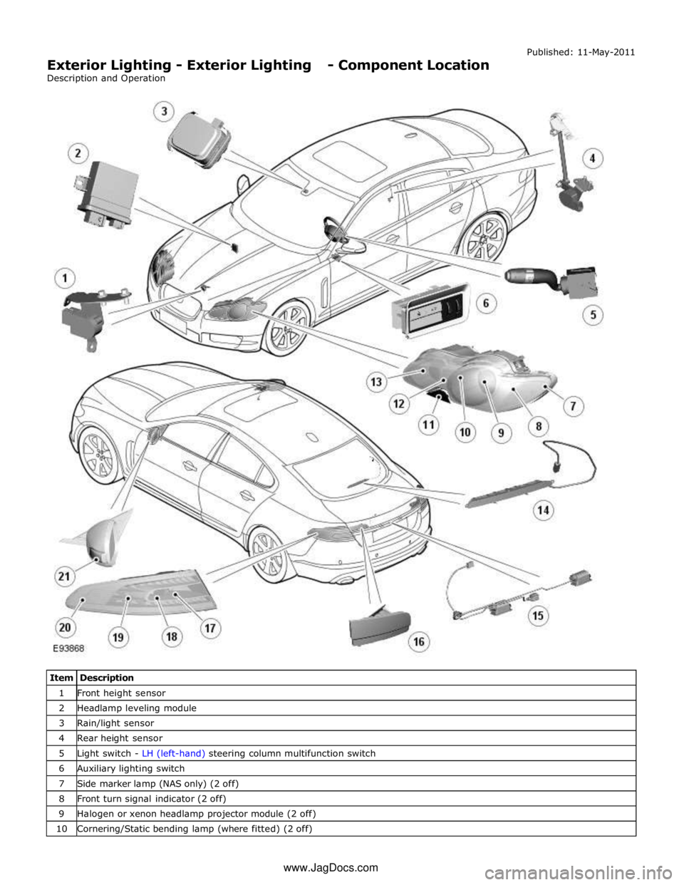
1 Front height sensor 2 Headlamp leveling module 3 Rain/light sensor 4 Rear height sensor 5 Light switch - LH (left-hand) steering column multifunction switch 6 Auxiliary lighting switch 7 Side marker lamp (NAS only) (2 off) 8 Front turn signal indicator (2 off) 9 Halogen or xenon headlamp projector module (2 off) 10 Cornering/Static bending lamp (where fitted) (2 off) www.JagDocs.com
Page 2021 of 3039

12 Front side lamp (2 off) 13 High beam only halogen lamp (2 off) 14 High Mounted Stop Lamp (HMSL) LED (light emitting diode)'s 15 License plate lamps (2 off) 16 Rear fog lamp (2 off) 17 Rear turn signal indicator (2 off) 18 Reverse lamp (2 off) 19 Side lamp/stop lamp LED's (2 off) 20 Side marker LED's (All markets) (2 off) 21 Side repeater lamp (2 off)