2010 JAGUAR XFR Parking
[x] Cancel search: ParkingPage 1852 of 3039

Symptom Possible Causes Action Parking aid sensors are being
returned with no faults found
or signs of water
ingress/corrosion Possible issue with sensor connectors
not latched correctly
When either no/intermittent operation has been
reported the following action should be taken
1. Using Datalogger, identify the position of the
suspect parking aid sensor within the bumper
2. Visually locate the position of the suspect
parking aid sensor. Inspect and provide details in
claim if the sensor has any sign of physical
damage
3. Remove the bumper. Disconnect the wiring at
the main harness connector. Inspect the main
harness connectors and terminals for signs of
damage, backed out pins, corrosion and water
ingress, or damage to the seals. Provide details in
claim if any of the above symptoms are present
4. Attempt to remove the harness connector from
the suspect parking aid sensor without using the
connector latch i.e. lightly pull back on ALL wires
together, ensuring the harness is held close to the
back of the connector, not elsewhere on the wiring
harness. DO NOT apply excessive force. If the
connector can be removed without using the latch,
provide details in claim if connector is loose. If the
connector is fully latched, disconnect it from the
sensor
5. Inspect and provide details in claim if the
suspect sensor harness connector has any sign of
water ingress/corrosion
6. Inspect and provide details in claim if the
suspect parking aid sensor harness connector
shows any sign that the terminals have backed-out
of the connector or for any damage to the terminal
seals. Replace/repair the harness as required and
proceed
7. Remove the suspect parking aid sensor from the
bumper. Inspect the parking aid sensor connector
for signs of water ingress/corrosion. Provide details
in claim if corrosion/water ingress is present
8. Exchange the suspect parking aid sensor with
another parking aid sensor within the bumper that
is performing correctly. Reconnect all sensors and
reconnect the bumper main harness connector.
Repeat step 1. Confirm if the original fault now
appears at the new position of the suspect parking
aid sensor, if so, proceed to step 10
9. If not, carry out the appropriate open circuit and
short circuit checks between the original suspect
parking aid sensor harness connector and the
parking aid control module
10. Refit the parking aid sensors to their original
position in the bumper
11. Reconnect the parking aid sensor to the
bumper harness connector. Reconnect main harness
connector and refit the bumper
12. Repeat Step 1. If fault is still present, replace
only the faulty sensor
PINPOINT TEST A : PARKING AID SYSTEM NOT FUNCTIONING CORRECTLY WITH NO DTCS LOGGED TEST
CONDITIONS DETAILS/RESULTS/ACTIONS A1: PERMANENT FAULT 1 When the parking aid system is activated, there is a vibration on the parking aid sensor membrane. This can be verified by touching the parking aid sensor face with a hard item such as a pencil, ball-pen, small
screwdriver, or fingernail. Ensure no damage is caused to sensor painted surface Are the parking aid sensor(s) vibrating? Yes
GO to A2. No
GO to A5. A2: SENSORS VIBRATING WITH PARKING AID FAULT 1 Clean the parking aid sensor face Parking aid system functioning correctly? Yes
No further action required
No www.JagDocs.com
Page 1853 of 3039

A3: SENSORS VIBRATING WITH PARKING AID FAULT 1 Check parking aid sensors correctly mounted. Parking aid sensor holder correctly mounted. Parking aid sensor decoupler ring fitted or fitted correctly. Parking aid sensor positioning correct. Parking aid sensor
painted without being removed from the bumper assembly or not painted to manufacturer specification.
Rectify as required Parking aid system functioning correctly? Yes
No further action required
No
GO to A4. A4: SENSORS VIBRATING WITH PARKING AID FAULT 1 Carry out speaker test. Only applicable to vehicles with rear hard wired parking aid speakers. Check the parking aid speaker wiring circuit and connector. Rectify as required. Check and install a new parking aid
speaker as required. Vehicles with audio parking aid system. Confirm audio system is functioning
correctly. Refer to the relevant section of the workshop manual Parking aid system functioning correctly Yes
No further action required A5: SENSORS NOT VIBRATING WITH PARKING AID FAULT 1 Isolate the fault to front or rear parking aid sensors Are all rear parking aid sensors vibrating? Yes
GO to A6. No
GO to A10. A6: FRONT SENSORS NOT VIBRATING WITH PARKING AID FAULT 1 Check the parking aid control module is correctly configured. Check and update the car configuration file as required Parking aid system functioning correctly? Yes
No further action required
No
GO to A7. A7: FRONT SENSORS NOT VIBRATING WITH PARKING AID FAULT 1 Check the correct parking aid control module is installed to the vehicle Parking aid system functioning correctly? Yes
No further action required
No
GO to A8. A8: FRONT SENSORS NOT VIBRATING WITH PARKING AID FAULT 1 If all 4 front parking aid sensors are not vibrating, carry out harness test on common ground, power supply. Check main parking aid harness connector to bumper harness connector. Rectify as required Parking aid system functioning correctly? Yes
No further action required
No
GO to A9. A9: FRONT SENSORS NOT VIBRATING WITH PARKING AID FAULT 1 Check and install a new parking aid control module as required. Refer to the warranty policy and procedures manual, or determine if any prior approval programme is in operation, prior to the installation
of a new module/component Parking aid system functioning correctly Yes
No further action required A10: REAR SENSORS NOT VIBRATING WITH PARKING AID FAULT 1 Check the parking aid control module is correctly configured. Check and update the car configuration file as required Parking aid system functioning correctly? Yes
No further action required
No
GO to A11. A11: REAR SENSORS NOT VIBRATING WITH PARKING AID FAULT 1 If all 4 rear parking aid sensors are not vibrating, carry out harness test on common ground, power supply. Check main parking aid harness connector to bumper harness connector. Rectify as required Parking aid system functioning correctly Yes
No further action required
No
GO to A12. A12: REAR SENSORS NOT VIBRATING WITH PARKING AID FAULT 1 Check and install a new parking aid control module as required. Refer to the warranty policy and procedures manual, or determine if any prior approval programme is in operation, prior to the installation
of a new module/component
Page 1854 of 3039
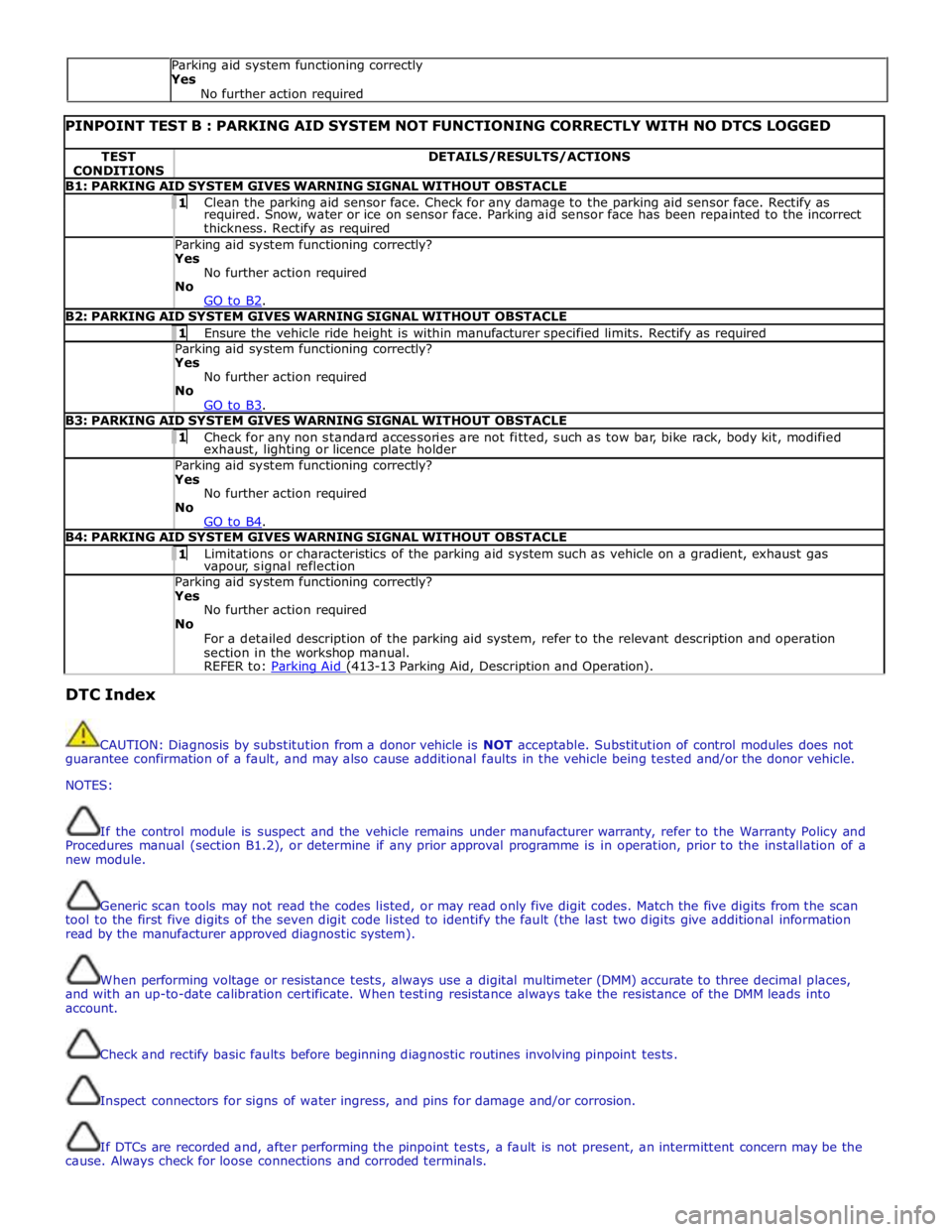
PINPOINT TEST B : PARKING AID SYSTEM NOT FUNCTIONING CORRECTLY WITH NO DTCS LOGGED TEST
CONDITIONS DETAILS/RESULTS/ACTIONS B1: PARKING AID SYSTEM GIVES WARNING SIGNAL WITHOUT OBSTACLE 1 Clean the parking aid sensor face. Check for any damage to the parking aid sensor face. Rectify as required. Snow, water or ice on sensor face. Parking aid sensor face has been repainted to the incorrect
thickness. Rectify as required Parking aid system functioning correctly? Yes
No further action required
No
GO to B2. B2: PARKING AID SYSTEM GIVES WARNING SIGNAL WITHOUT OBSTACLE 1 Ensure the vehicle ride height is within manufacturer specified limits. Rectify as required Parking aid system functioning correctly? Yes
No further action required
No
GO to B3. B3: PARKING AID SYSTEM GIVES WARNING SIGNAL WITHOUT OBSTACLE 1 Check for any non standard accessories are not fitted, such as tow bar, bike rack, body kit, modified exhaust, lighting or licence plate holder Parking aid system functioning correctly? Yes
No further action required
No
GO to B4. B4: PARKING AID SYSTEM GIVES WARNING SIGNAL WITHOUT OBSTACLE 1 Limitations or characteristics of the parking aid system such as vehicle on a gradient, exhaust gas vapour, signal reflection Parking aid system functioning correctly? Yes
No further action required
No
For a detailed description of the parking aid system, refer to the relevant description and operation
section in the workshop manual.
REFER to: Parking Aid (413-13 Parking Aid, Description and Operation). DTC Index
CAUTION: Diagnosis by substitution from a donor vehicle is NOT acceptable. Substitution of control modules does not
guarantee confirmation of a fault, and may also cause additional faults in the vehicle being tested and/or the donor vehicle.
NOTES:
If the control module is suspect and the vehicle remains under manufacturer warranty, refer to the Warranty Policy and
Procedures manual (section B1.2), or determine if any prior approval programme is in operation, prior to the installation of a
new module.
Generic scan tools may not read the codes listed, or may read only five digit codes. Match the five digits from the scan
tool to the first five digits of the seven digit code listed to identify the fault (the last two digits give additional information
read by the manufacturer approved diagnostic system).
When performing voltage or resistance tests, always use a digital multimeter (DMM) accurate to three decimal places,
and with an up-to-date calibration certificate. When testing resistance always take the resistance of the DMM leads into
account.
Check and rectify basic faults before beginning diagnostic routines involving pinpoint tests.
Inspect connectors for signs of water ingress, and pins for damage and/or corrosion.
If DTCs are recorded and, after performing the pinpoint tests, a fault is not present, an intermittent concern may be the
cause. Always check for loose connections and corroded terminals. Parking aid system functioning correctly
Yes
No further action required
Page 1856 of 3039
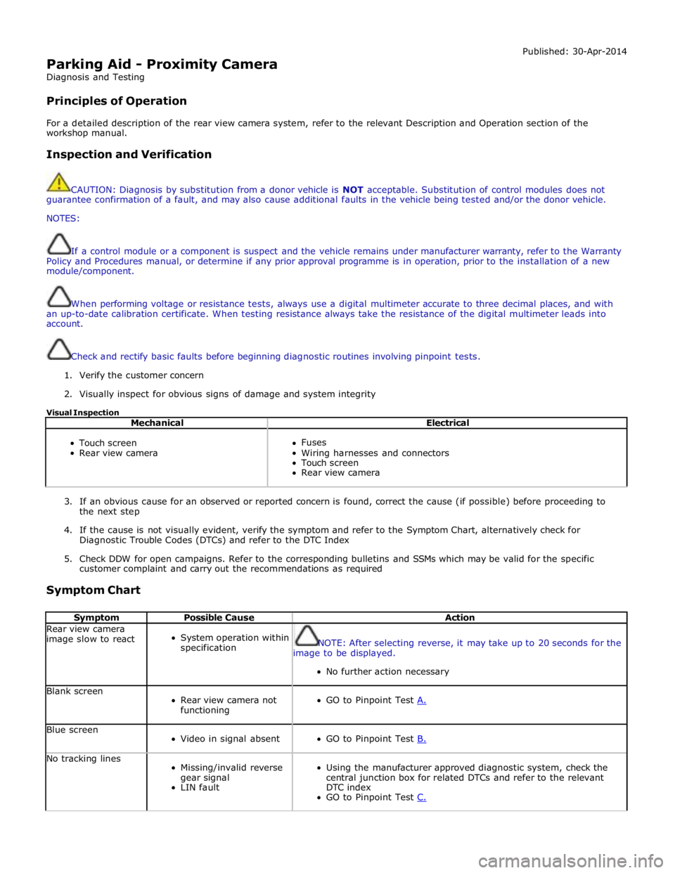
Parking Aid - Proximity Camera
Diagnosis and Testing
Principles of Operation Published: 30-Apr-2014
For a detailed description of the rear view camera system, refer to the relevant Description and Operation section of the
workshop manual.
Inspection and Verification
CAUTION: Diagnosis by substitution from a donor vehicle is NOT acceptable. Substitution of control modules does not
guarantee confirmation of a fault, and may also cause additional faults in the vehicle being tested and/or the donor vehicle.
NOTES:
If a control module or a component is suspect and the vehicle remains under manufacturer warranty, refer to the Warranty
Policy and Procedures manual, or determine if any prior approval programme is in operation, prior to the installation of a new
module/component.
When performing voltage or resistance tests, always use a digital multimeter accurate to three decimal places, and with
an up-to-date calibration certificate. When testing resistance always take the resistance of the digital multimeter leads into
account.
Check and rectify basic faults before beginning diagnostic routines involving pinpoint tests.
1. Verify the customer concern
2. Visually inspect for obvious signs of damage and system integrity
Visual Inspection
Mechanical Electrical
Touch screen
Rear view camera
Fuses
Wiring harnesses and connectors
Touch screen
Rear view camera
3. If an obvious cause for an observed or reported concern is found, correct the cause (if possible) before proceeding to
the next step
4. If the cause is not visually evident, verify the symptom and refer to the Symptom Chart, alternatively check for
Diagnostic Trouble Codes (DTCs) and refer to the DTC Index
5. Check DDW for open campaigns. Refer to the corresponding bulletins and SSMs which may be valid for the specific
customer complaint and carry out the recommendations as required
Symptom Chart
Symptom Possible Cause Action Rear view camera
image slow to react
System operation within
specification
NOTE: After selecting reverse, it may take up to 20 seconds for the
image to be displayed.
No further action necessary Blank screen
Rear view camera not
functioning
GO to Pinpoint Test A. Blue screen
Video in signal absent
GO to Pinpoint Test B. No tracking lines
Missing/invalid reverse
gear signal
LIN fault
Using the manufacturer approved diagnostic system, check the
central junction box for related DTCs and refer to the relevant
DTC index
GO to Pinpoint Test C.
Page 1859 of 3039
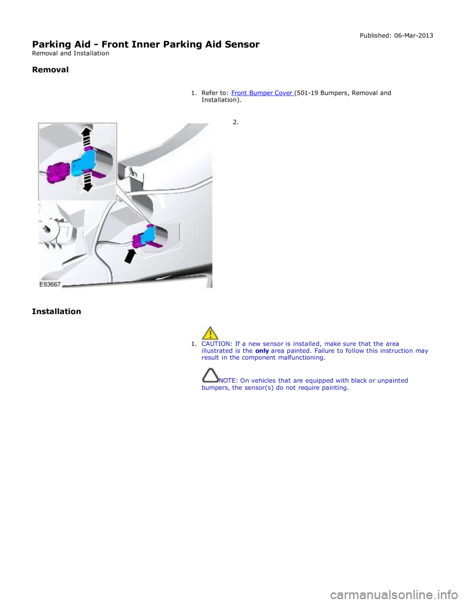
Parking Aid - Front Inner Parking Aid Sensor
Removal and Installation
Removal Published: 06-Mar-2013
1. Refer to: Front Bumper Cover (501-19 Bumpers, Removal and Installation).
2.
Installation
1. CAUTION: If a new sensor is installed, make sure that the area
illustrated is the only area painted. Failure to follow this instruction may
result in the component malfunctioning.
NOTE: On vehicles that are equipped with black or unpainted
bumpers, the sensor(s) do not require painting.
Page 1861 of 3039
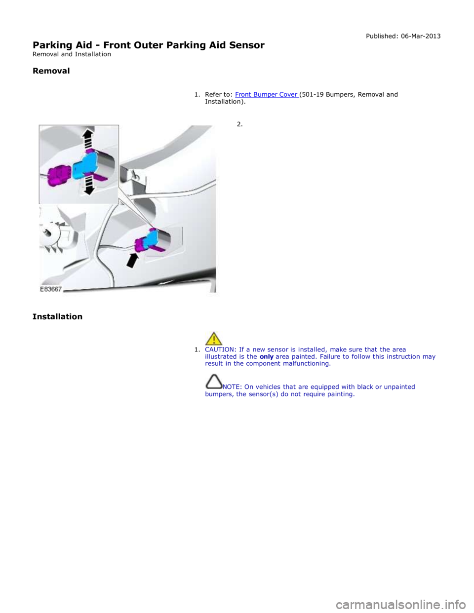
Parking Aid - Front Outer Parking Aid Sensor
Removal and Installation
Removal Published: 06-Mar-2013
1. Refer to: Front Bumper Cover (501-19 Bumpers, Removal and Installation).
2.
Installation
1. CAUTION: If a new sensor is installed, make sure that the area
illustrated is the only area painted. Failure to follow this instruction may
result in the component malfunctioning.
NOTE: On vehicles that are equipped with black or unpainted
bumpers, the sensor(s) do not require painting.
Page 1949 of 3039
systems.
A typical example of information transfer is vehicle speed information from the ABS (anti-lock brake system) module used to
control the automatic volume control function. The vehicle speed information from the ABS module is sent on the high speed
CAN network and collected by the instrument panel gateway. The signal is passed to the medium speed CAN network and onto the ICM gateway. The ICM calculates the volume adjustment required. The corrected audio volume level signal is sent on the
MOST network to the IAM or Power amplifier (dependant on vehicle equipment level) for output to the speaker system.
AUDIO SYSTEM USER CONTROLS
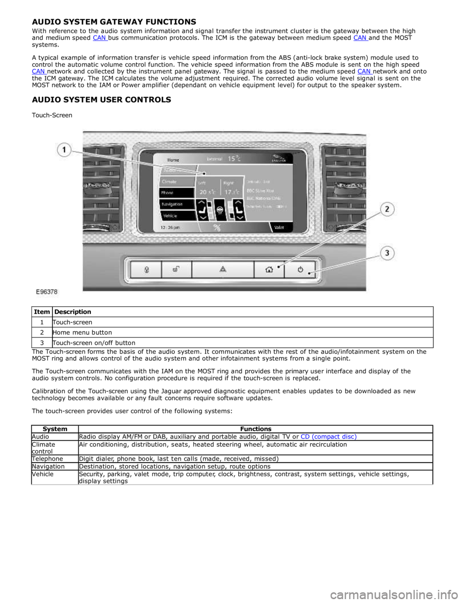
Touch-Screen
Item Description 1 Touch-screen 2 Home menu button 3 Touch-screen on/off button The Touch-screen forms the basis of the audio system. It communicates with the rest of the audio/infotainment system on the
MOST ring and allows control of the audio system and other infotainment systems from a single point.
The Touch-screen communicates with the IAM on the MOST ring and provides the primary user interface and display of the
audio system controls. No configuration procedure is required if the touch-screen is replaced.
Calibration of the Touch-screen using the Jaguar approved diagnostic equipment enables updates to be downloaded as new
technology becomes available or any fault concerns require software updates.
The touch-screen provides user control of the following systems:
System Functions Audio Radio display AM/FM or DAB, auxiliary and portable audio, digital TV or CD (compact disc) Climate
control Air conditioning, distribution, seats, heated steering wheel, automatic air recirculation Telephone Digit dialer, phone book, last ten calls (made, received, missed) Navigation Destination, stored locations, navigation setup, route options Vehicle
Security, parking, valet mode, trip computer, clock, brightness, contrast, system settings, vehicle settings, display settings
Page 1977 of 3039

In addition to the standard navigation system there are two market dependant systems that supply extra information to the
navigation system and the driver. These are:
TMC (traffic message channel) (Europe only)
VICS (vehicle information and communication system) (Japan only)
The TMC (traffic message channel) is a function of the FM (frequency modulation)RDS (radio data system). The system
broadcasts real-time traffic and weather information. Data messages are received and decoded by the TMC (traffic message
channel) integral receiver and processed by the navigation computer. TMC (traffic message channel) messages can be filtered
by the navigation computer so that only those relevant to the current journey are displayed, allowing the navigation system to
offer dynamic route guidance - alerting the driver of a problem on the planned route and calculating an alternative route to
avoid the incident. All TMC (traffic message channel) events on the map can be viewed not just the ones on the calculated
route.
TMC (traffic message channel) traffic information systems conform to a global standard that has been adopted by traffic data
gatherers, information service providers, broadcasters and vehicle/receiver manufacturers.
All TMC (traffic message channel) receivers use the same list of event codes, while the location database (on the map disc)
contains both a country-specific set of location codes for the strategic European road network.
TMC (traffic message channel) traffic data is currently broadcast in many European countries.
The VICS (vehicle information and communication system) is broadcast in the Japanese market.
The VICS (vehicle information and communication system) supplies information to enable the navigation computer to re-route
the navigation guidance or to inform the vehicle driver of traffic conditions in the vehicles vicinity. Information is provided to
the system through 3 routes:
RF (radio frequency) transmission
Infra-red transmission
FM multiplex transmissions
The RF (radio frequency) transmissions are generally transmitted from road side beacons mainly on expressways. The
information transmitted is as follows:
Traffic congestion
Travel time to next intersection
Traffic conditions in surrounding areas and expressway turn offs
Traffic accidents
Speed limits
Lane regulations
Tire change
Parking availability at expressway service areas and parking areas
Infra-Red transmissions are transmitted from road side beacons on major trunk roads. The information transmitted is:
Traffic congestion and travel time
Traffic accidents
Breakdowns
Road works restrictions
Parking availability
FM transmissions are broadcast as part of the FM multiplex broadcasting system from NHK FM stations. Information transmitted is:
Traffic congestion and travel time for wide areas
Traffic accidents, road works, speed limits and lane restrictions for a wide area
Parking availability information
The traffic data is split from the normal FM transmissions by the diversity antenna module.
Selection of 'Navigation' on the Touch-screen home menu and subsequent sub-menu selection sends a control request signal to
the navigation computer on the MOST (media orientated systems transport) ring. The requested control information is
processed by the navigation computer.
If voice guidance is operational the voice signal information is relayed from the navigation computer on the MOST (media
orientated systems transport) ring to either the IAM (integrated audio unit) or Power Amplifier, dependant on equipment level,
for output on the speaker system. The navigation audio output is through the front speakers whilst the background audio, for
example radio or CD (compact disc), is played at a reduced volume on the rear speakers.
The GPS signal is available to the navigation system at all times when the vehicle ignition is switched on.
Navigation user voice commands are made using the JaguarVoice system. The ICM (information control module) processes the
analogue signal from the JaguarVoice switch into a digital signal. The digital signal is passed from the ICM (information control
module) onto the MOST (media orientated systems transport) system to the JaguarVoice control unit which is integral with the
navigation computer.
The navigation computer sends an instruction via the MOST (media orientated systems transport) ring to the IAM (integrated
audio module) to turn on the microphone facility.
The microphone is hardwired to the IAM (integrated audio module). The spoken voice command signals are relayed from the
IAM (integrated audio module) via the MOST (media orientated systems transport) ring to the navigation computer for