2010 JAGUAR XFR Parking
[x] Cancel search: ParkingPage 1981 of 3039

Navigation Destination, stored locations, navigation setup, route options Vehicle
Security, parking, valet mode, trip computer, clock, brightness, contrast, system settings, vehicle settings, display settings The screen is a touch sensitive 7 inch LCD (liquid crystal display) VGA screen containing 800 x 480 pixels in a 15:9 format. The
screen processes its own video for system operation but receives the navigation graphics from the navigation computer.
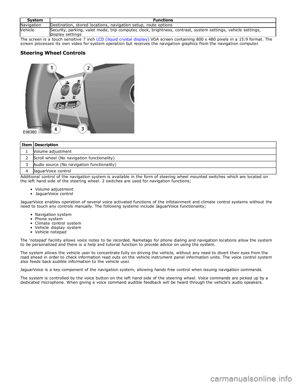
Steering Wheel Controls
Item Description 1 Volume adjustment 2 Scroll wheel (No navigation functionality) 3 Audio source (No navigation functionality) 4 JaguarVoice control Additional control of the navigation system is available in the form of steering wheel mounted switches which are located on
the left hand side of the steering wheel. 2 switches are used for navigation functions;
Volume adjustment
JaguarVoice control
JaguarVoice enables operation of several voice activated functions of the infotainment and climate control systems without the
need to touch any controls manually. The following systems include JaguarVoice functionality;
Navigation system
Phone system
Climate control system
Vehicle display system
Vehicle notepad
The 'notepad' facility allows voice notes to be recorded. Nametags for phone dialing and navigation locations allow the system
to be personalized and there is a help and tutorial function to provide advice on using the system.
The system allows the vehicle user to concentrate fully on driving the vehicle, without any need to divert their eyes from the
road ahead in order to check information read outs on the vehicle instrument panel information units. The voice control system
also feeds back audible information to the vehicle user.
JaguarVoice is a key component of the navigation system, allowing hands free control when issuing navigation commands.
The system is controlled by the voice button on the left hand side of the steering wheel. Voice commands are picked up by a
dedicated microphone. When giving a voice command audible feedback will be heard through the vehicle’s audio speakers.
Page 2019 of 3039

Low beam headlamp bulb - Vehicles with conventional headlamps - non Federal H7 Low beam headlamp bulb - Vehicles with conventional headlamps - Federal H11 Low beam headlamp bulb - Vehicles with xenon headlamps D1S High beam headlamp bulb H7 Cornering lamp bulb H8 Side repeater lamp bulb WY5W Side marker lamp bulb - Federal W5W Front turn signal lamp bulb - non Federal PY21W Front turn signal lamp bulb - Federal 3457 AK Rear turn signal lamp bulb PY19W Front side/parking lamp bulb - Vehicles built up to 01/2009 W5W halogen cool blue Front side/parking lamp bulb - Vehicles built 02/2009 onwards W5W Reversing lamp bulb PS19W
Page 2066 of 3039

Published: 11-May-2011
Daytime Running Lamps (DRL) - Daytime Running Lamps (DRL) - System
Operation and Component Description
Description and Operation
CENTRAL JUNCTION BOX (CJB) System Operation
The CJB (central junction box) controls the operation of the DRL (daytime running lamps). The DRL are activated once the CJB detects an ignition on power mode 6 signal.
The CJB also monitors the lighting control switch and the auto lamps feature and overrides the DRL if required.
DAYTIME RUNNING LAMPS - CANADA Component Description
The DRL for this market use full intensity low beam headlamps. The side marker lamps, tail lamps and license plate lamps will be on, but instrument cluster illumination will be off. DRL are active when the following parameters are met:
PARK is not selected on the electronic transmission selector
Electronic Parking Brake (EPB) is off
Power mode 6 (ignition on) detected by the CJB The CJB receives an engine running signal The lighting control switch is in the off or side lamps position.
NOTES:
If the lighting control switch is moved to the headlamp position, DRL are deactivated and normal side lamp and headlamp functionality is operational.
When DRL are active, the headlamp flash function using the left hand steering column multifunction switch will operate normally.
The high beam headlamp function using the left hand steering column stalk switch will be deactivated. When the transmission
is in PARK, DRL are turned off. This is to reduce battery discharge during long periods of engine idling in cold climate conditions. When the electronic transmission selector is moved from the PARK position, normal DRL functionality is restored.
DAYTIME RUNNING LAMPS - DENMARK, HOLLAND, NORWAY, SWEDEN, FINLAND AND POLAND
NOTE: DRL for Poland is on vehicles from 2008MY.
DRL for these markets use full intensity low beam headlamps. Side lamps and license plate lamps will be on, but instrument cluster illumination will be off. DRL are active when the following parameters are met:
Power mode 6 (ignition on) detected by the CJB The CJB receives an engine running signal The lighting control switch is in the off position.
NOTE: When DRL are active, the headlamp flash function using the left hand steering column multifunction switch will operate normally. The high beam headlamp function using the left hand steering column stalk switch will be deactivated.
If the lighting control switch is moved to the side lamp or headlamp positions, DRL are deactivated and normal side lamp and headlamp functionality is operational.
AUTOMATIC HEADLAMPS
On vehicles fitted with the automatic headlamps feature, DRL are overridden if the lighting control switch is in the 'Auto' position and the CJB receives a signal from the rain/light sensor to activate the exterior lights.
When the CJB receives a signal to de-activate the automatic headlamps feature the DRL function is restored providing the parameters for DRL activation are met.
Page 2071 of 3039

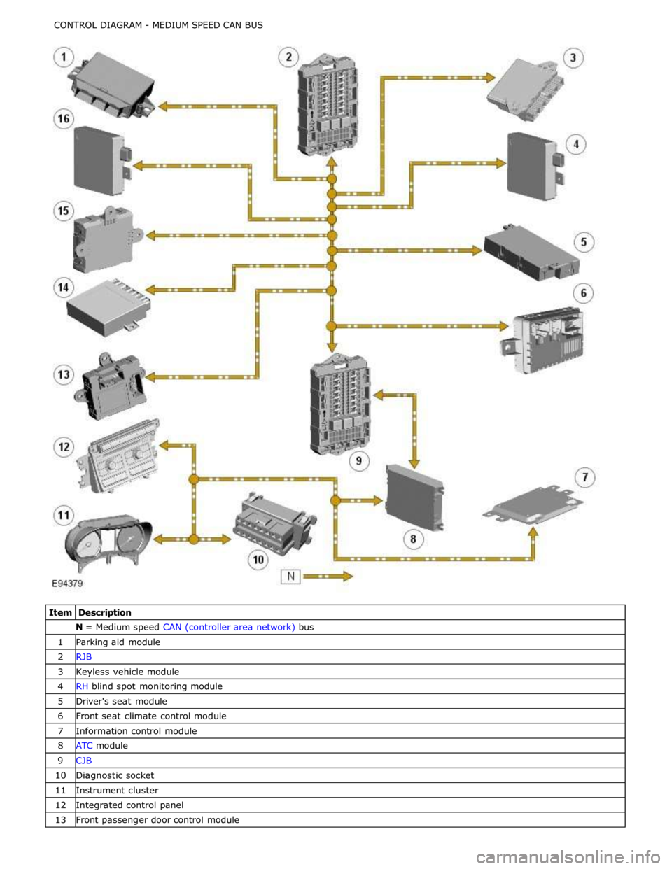
N = Medium speed CAN (controller area network) bus 1 Parking aid module 2 RJB 3 Keyless vehicle module 4 RH blind spot monitoring module 5 Driver's seat module 6 Front seat climate control module 7 Information control module 8 ATC module 9 CJB 10 Diagnostic socket 11 Instrument cluster 12 Integrated control panel 13 Front passenger door control module
Page 2095 of 3039

DTC Description Possible Causes Action Write target SID
synchronisation error
following re-programming
Noise/EMC related error B100A63
Fuel Pump
Authorisation
RJB fault
Low speed CAN fault
Instrument cluster fault
Low battery voltage <9V Check power and ground supplies to RJB and instrument cluster.
Check CAN communications between RJB and instrument cluster.
Check battery is in fully charged and serviceable condition, refer
to the battery care manual B102612
Steering Column
Lock
Steering column lock
ground circuit - short to
power Refer to the electrical circuit diagrams and check steering column
lock ground circuit for short to power B108783 LIN Bus "A"
The checksum of the
received LIN frame is
incorrect Check the battery monitoring system and rear parking aid system
for DTCs and refer to relevant DTC Index B108786 LIN Bus "A"
The header of the LIN
message received is
incorrect Carry out any pinpoint test associated with this DTC using the
manufacturer approved diagnostic system. Check the battery
monitoring system and rear parking aid system for DTCs and
refer to relevant DTC Index B108788 LIN Bus "A"
Battery monitoring
system LIN circuit - short
to ground, power Carry out any pinpoint test associated with this DTC using the
manufacturer approved diagnostic system. Refer to the electrical
circuit diagrams and check battery monitoring system LIN circuit
for short to ground, power B108A23 Start Button
Start/Stop switch digital
input signal circuit -
stuck low Carry out any pinpoint test associated with this DTC using the
manufacturer approved diagnostic system. Refer to the electrical
circuit diagrams and check Start/Stop switch digital input signal
circuit for short to ground B10A111 Trailer Tow
Detection
Trailer tow detection
digital input circuit -
short to ground Carry out any pinpoint test associated with this DTC using the
manufacturer approved diagnostic system. Refer to the electrical
circuit diagrams and check trailer tow detection digital input
circuit for short to ground B10AF12 Blower Fan Relay
High Side output not
driven - Diagnosis
feedback indicates output
is short to power Refer to the electrical circuit diagrams and check blower motor
supply circuit for short to power B10AF14 Blower Fan Relay
High Side output not
driven - Diagnosis
feedback indicates output
is short to ground, open
circuit Refer to the electrical circuit diagrams and check blower motor
supply circuit for short to ground, open circuit B10AF93 Blower Fan Relay
High Side output not
driven - Diagnosis
feedback indicates output
is at open load or short
to power Carry out any pinpoint test associated with this DTC using the
manufacturer approved diagnostic system. Refer to the electrical
circuit diagrams and check blower motor supply circuit for short
to power, open circuit B10DD11 Airbag Deployed
Airbag deployed digital
input signal circuit - short
to ground Carry out any pinpoint test associated with this DTC using the
manufacturer approved diagnostic system. Refer to the electrical
circuit diagrams and check airbag deployed digital input signal
circuit for short to ground B10DD15 Airbag Deployed
Airbag deployed digital
input signal circuit - short
to power, open circuit Carry out any pinpoint test associated with this DTC using the
manufacturer approved diagnostic system. Refer to the electrical
circuit diagrams and check airbag deployed digital input signal
circuit for short to power, open circuit B10DD38 Airbag Deployed
Signal frequency incorrect Check the RCM for related DTCs and refer to the relevant DTC
Index B10DE11
Low Fuel Warning
Switch
Diesel run-dry switch
analogue input circuit -
short to ground Carry out any pinpoint test associated with this DTC using the
manufacturer approved diagnostic system. Refer to the electrical
circuit diagrams and check diesel run-dry switch analogue input
circuit for short to ground www.JagDocs.com
Page 2096 of 3039

DTC Description Possible Causes Action B10DE15
Low Fuel Warning
Switch
Diesel run-dry switch
analogue input circuit -
short to power, open
circuit Carry out any pinpoint test associated with this DTC using the
manufacturer approved diagnostic system. Refer to the electrical
circuit diagrams and check diesel run-dry switch analogue input
circuit for short to power, open circuit B111211 Park Aid Ignition
Parking aid ignition
supply circuit - short to
ground Carry out any pinpoint test associated with this DTC using the
manufacturer approved diagnostic system. Refer to the electrical
circuit diagrams and check parking aid ignition supply circuit for
short to ground B111212 Park Aid Ignition
Parking aid ignition
supply circuit - short to
power Refer to the electrical circuit diagrams and check parking aid
ignition supply circuit for short to power B111511
High Mounted
Stop Lamp
Control
High mounted stop lamp
control circuit - short to
ground Carry out any pinpoint test associated with this DTC using the
manufacturer approved diagnostic system. Refer to the electrical
circuit diagrams and check high mounted stop lamp control circuit
for short to ground B111611 Left Tail Lamp
Left hand tail lamp
control circuit - short to
ground Carry out any pinpoint test associated with this DTC using the
manufacturer approved diagnostic system. Refer to the electrical
circuit diagrams and check left hand tail lamp control circuit for
short to ground B111711 Right Tail Lamp
Right hand tail lamp
control circuit - short to
ground Carry out any pinpoint test associated with this DTC using the
manufacturer approved diagnostic system. Refer to the electrical
circuit diagrams and check right hand tail lamp control circuit for
short to ground B111A11
Number Plate
Lamps
Right hand or left hand
number plate lamp
control circuits - short to
ground Carry out any pinpoint test associated with this DTC using the
manufacturer approved diagnostic system. Refer to the electrical
circuit diagrams and check right hand and left hand number plate
lamp control circuits for short to ground B111A12
Number Plate
Lamps
Right hand or left hand
number plate lamp
control circuits - short to
power Refer to the electrical circuit diagrams and check right hand and
left hand number plate lamp control circuits for short to power B111A13
Number Plate
Lamps
Right hand or left hand
number plate lamp
control circuits - open
circuit Refer to the electrical circuit diagrams and check right hand and
left hand number plate lamp control circuits for open circuit B111A-15
Number Plate
Lamps - circuit
short to battery
or open
Right or left side licence
plate lamp(s) inoperative
Right or left side licence
plate lamp control
circuits - short circuit to
power, open circuit, high
resistance
Refer to the electrical circuit diagrams and check right
side and left side licence plate lamp control circuits for
short circuit to power, open circuit, high resistance. Repair
wiring harness as required. Clear DTC and retest B111D12
Boot/Trunk Motor
Open
Luggage compartment lid
latch actuator control
circuit - short to power Carry out any pinpoint test associated with this DTC using the
manufacturer approved diagnostic system. Refer to the electrical
circuit diagrams and check luggage compartment lid latch
actuator control circuit for short to power B111D14
Boot/Trunk Motor
Open
Luggage compartment lid
latch actuator control
circuit - short to ground,
open circuit Carry out any pinpoint test associated with this DTC using the
manufacturer approved diagnostic system. Refer to the electrical
circuit diagrams and check luggage compartment lid latch
actuator control circuit for short to ground, open circuit B111E11 Boot/Trunk Lamps
Luggage compartment
lamp control circuit -
short to ground Carry out any pinpoint test associated with this DTC using the
manufacturer approved diagnostic system. Refer to the electrical
circuit diagrams and check luggage compartment lamp control
circuit for short to ground B111E12 Boot/Trunk Lamps
Luggage compartment
lamp control circuit -
short to power Refer to the electrical circuit diagrams and check luggage
compartment lamp control circuit for short to power
Page 2100 of 3039

DTC Description Possible Causes Action B1D3523 Hazard Switch
Hazard warning lamp
switch digital input circuit
- signal stuck low Carry out any pinpoint test associated with this DTC using the
manufacturer approved diagnostic system. Refer to the electrical
circuit diagrams and check hazard warning lamp switch digital
input circuit for short to ground U001988
Low Speed CAN
Communication
Bus
Bus off Carry out any pinpoint test associated with this DTC using the
manufacturer approved diagnostic system U014000
Lost
Communication
With Body
Control Module
No sub type information Carry out any pinpoint test associated with this DTC using the
manufacturer approved diagnostic system U015500
Lost
Communication
With Instrument
Panel Cluster
(IPC) Control
Module
No sub type information Carry out any pinpoint test associated with this DTC using the
manufacturer approved diagnostic system U015900
Lost
Communication
With Parking
Assist Control
Module "A"
No sub type information Carry out any pinpoint test associated with this DTC using the
manufacturer approved diagnostic system U016400
Lost
Communication
With HVAC
Control Module
No sub type information Carry out any pinpoint test associated with this DTC using the
manufacturer approved diagnostic system U021400
Lost
Communication
With Remote
Function
Actuation
No sub type information Carry out any pinpoint test associated with this DTC using the
manufacturer approved diagnostic system U030046
Internal Control
Module Software
Incompatibility
Calibration/parameter
memory failure Suspect the RJB. Check and install a new RJB as required, refer
to the new module/component installation note at the top of the
DTC Index U100000
Solid State Driver
Protection Active
-Driver Disabled
No sub type information Carry out any pinpoint test associated with this DTC using the
manufacturer approved diagnostic system U1A1449
CAN Initialisation
Failure
Internal electronic failure Suspect the RJB. Check and install a new RJB as required, refer
to the new module/component installation note at the top of the
DTC Index U300049 Control Module
Internal electronic failure Suspect the RJB. Check and install a new RJB as required, refer
to the new module/component installation note at the top of the
DTC Index U300055 Control Module
Not configured Re-configure the RJB using the manufacturer approved diagnostic
system www.JagDocs.com
Page 2150 of 3039

Symptom Possible Cause Action Vehicle’s current position
mark turns independently
Electrical harness open/short
circuit, dis-connected
Component failure
Vehicle on a turntable in a parking
building GO to Pinpoint Test E. Car current position not
stable
Electrical harness open/short
circuit, dis-connected
Component failure GO to Pinpoint Test F. Map display is incomplete
Map disc contaminated/damaged
Electrical harness open/short
circuit, dis-connected
Incorrect market map disc
Component failure GO to Pinpoint Test G. No navigation voice guidance
Voice guidance soft key set to OFF
position
Volume level set too low
Component failure GO to Pinpoint Test H. No response to pressing
navigation menu
Interruption during map disc
update
Electrical harness open/short
circuit, dis-connected
Incorrect Navigation Control
Module (NCM) installed
Incorrect car configuration data
received GO to Pinpoint Test I. 'NO DVD PLEASE INSERT MAP
DVD' message is displayed
A disc other than the map disc is
inserted Insert the correct map disc 'UNABLE TO READ DATA
CONSULT YOUR DEALER'
message is displayed
DVD player abnormality Check and install a new Navigation Control Module
(NCM) as required. Refer to the new
module/component installation note at top of DTC
Index. 'UNABLE TO READ DATA TEMPERATURE IS TOO HIGH'
message is displayed
Operating temperature has been
exceeded
Navigation Control Module (NCM)
internal temperature is high Move the vehicle to a cool location, and turn the
engine OFF. Wait for a while, then verify conditions
again. If the temperature around the Navigation
Control Module (NCM) is high, take measures to lower
temperature 'UNABLE TO READ DVD
CORRECTLY CHECK IF THE
DVD IS DAMAGED OR DIRTY'
message is displayed
Check map disc for contamination,
deformation, cracks, scratches or
non-genuine disc Clean the map disc and retest, replace the map disc 'UNABLE TO READ DATA
CHECK IF MAP DVD IS
CORRECT' message is displayed
Incorrect DVD map disc is inserted Insert a map disc with the correct part number Pinpoint Tests
NOTES:
If the control module or a component is suspect and the vehicle remains under manufacturer warranty, refer to the
Warranty Policy and Procedures manual (section B1.2), or determine if any prior approval Program is in operation, prior to the
installation of a new module/component.
Navigation Diagnostic Screen Access
1. With the vehicle at rest, place the ignition switch in either "ACC", "ON", or start the engine.
2.On the "Menu" screen, press the top center of the screen for more than three seconds.
3. Enter the PIN code, and then touch "OK". 660: Diagnosis Menu screen 661: System Check screen (DTC code
verification screen) 662: GPS Information screen.
4. The diagnostics screen will be displayed.
PINPOINT TEST A : POOR SATELLITE RECEPTION www.JagDocs.com