2010 JAGUAR XFR Parking
[x] Cancel search: ParkingPage 2151 of 3039
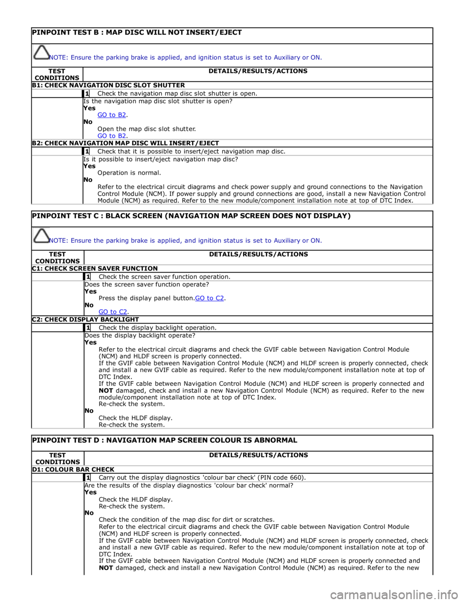
PINPOINT TEST B : MAP DISC WILL NOT INSERT/EJECT
NOTE: Ensure the parking brake is applied, and ignition status is set to Auxiliary or ON. TEST
CONDITIONS DETAILS/RESULTS/ACTIONS B1: CHECK NAVIGATION DISC SLOT SHUTTER 1 Check the navigation map disc slot shutter is open. Is the navigation map disc slot shutter is open? Yes
GO to B2. No
Open the map disc slot shutter.
GO to B2. B2: CHECK NAVIGATION MAP DISC WILL INSERT/EJECT 1 Check that it is possible to insert/eject navigation map disc. Is it possible to insert/eject navigation map disc? Yes
Operation is normal.
No
Refer to the electrical circuit diagrams and check power supply and ground connections to the Navigation
Control Module (NCM). If power supply and ground connections are good, install a new Navigation Control
Module (NCM) as required. Refer to the new module/component installation note at top of DTC Index.
PINPOINT TEST C : BLACK SCREEN (NAVIGATION MAP SCREEN DOES NOT DISPLAY)
NOTE: Ensure the parking brake is applied, and ignition status is set to Auxiliary or ON. TEST
CONDITIONS DETAILS/RESULTS/ACTIONS C1: CHECK SCREEN SAVER FUNCTION 1 Check the screen saver function operation. Does the screen saver function operate? Yes
Press the display panel button.GO to C2. No
GO to C2. C2: CHECK DISPLAY BACKLIGHT 1 Check the display backlight operation. Does the display backlight operate? Yes
Refer to the electrical circuit diagrams and check the GVIF cable between Navigation Control Module
(NCM) and HLDF screen is properly connected.
If the GVIF cable between Navigation Control Module (NCM) and HLDF screen is properly connected, check
and install a new GVIF cable as required. Refer to the new module/component installation note at top of
DTC Index.
If the GVIF cable between Navigation Control Module (NCM) and HLDF screen is properly connected and
NOT damaged, check and install a new Navigation Control Module (NCM) as required. Refer to the new
module/component installation note at top of DTC Index.
Re-check the system.
No
Check the HLDF display.
Re-check the system.
PINPOINT TEST D : NAVIGATION MAP SCREEN COLOUR IS ABNORMAL TEST
CONDITIONS DETAILS/RESULTS/ACTIONS D1: COLOUR BAR CHECK 1 Carry out the display diagnostics 'colour bar check' (PIN code 660). Are the results of the display diagnostics 'colour bar check' normal? Yes
Check the HLDF display.
Re-check the system.
No
Check the condition of the map disc for dirt or scratches.
Refer to the electrical circuit diagrams and check the GVIF cable between Navigation Control Module
(NCM) and HLDF screen is properly connected.
If the GVIF cable between Navigation Control Module (NCM) and HLDF screen is properly connected, check
and install a new GVIF cable as required. Refer to the new module/component installation note at top of
DTC Index.
If the GVIF cable between Navigation Control Module (NCM) and HLDF screen is properly connected and
NOT damaged, check and install a new Navigation Control Module (NCM) as required. Refer to the new
Page 2165 of 3039
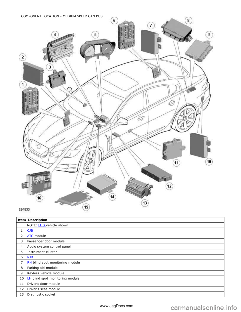
NOTE: LHD vehicle shown 1 CJB 2 ATC module 3 Passenger door module 4 Audio system control panel 5 Instrument cluster 6 RJB 7 RH blind spot monitoring module 8 Parking aid module 9 Keyless vehicle module 10 LH blind spot monitoring module 11 Driver's door module 12 Driver's seat module 13 Diagnostic socket COMPONENT LOCATION - MEDIUM SPEED CAN BUS
www.JagDocs.com
Page 2166 of 3039
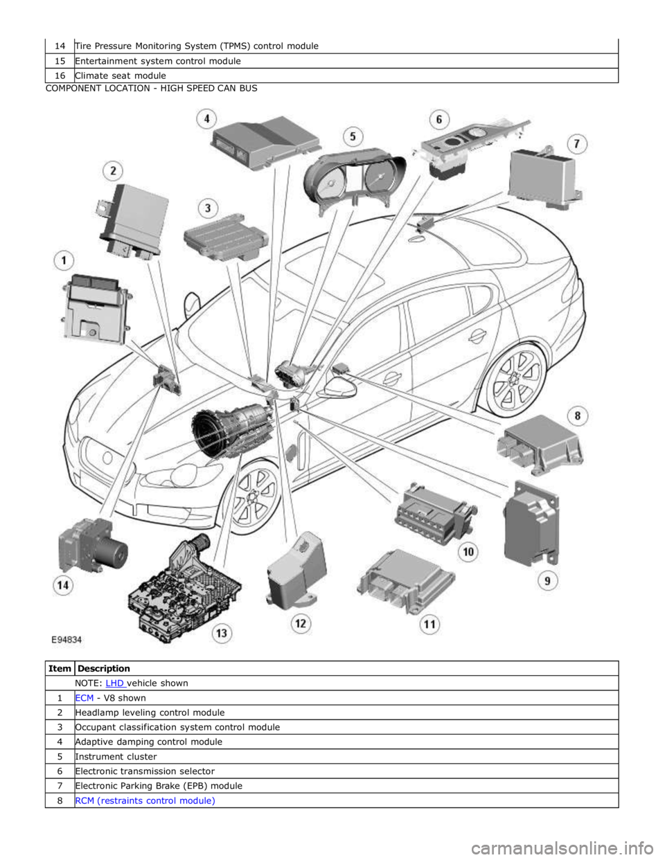
Tire Pressure Monitoring System (TPMS) control module 15 Entertainment system control module 16 Climate seat module COMPONENT LOCATION - HIGH SPEED CAN BUS
Item Description NOTE: LHD vehicle shown 1 ECM - V8 shown 2 Headlamp leveling control module 3 Occupant classification system control module 4 Adaptive damping control module 5 Instrument cluster 6 Electronic transmission selector 7 Electronic Parking Brake (EPB) module 8 RCM (restraints control module)
Page 2170 of 3039
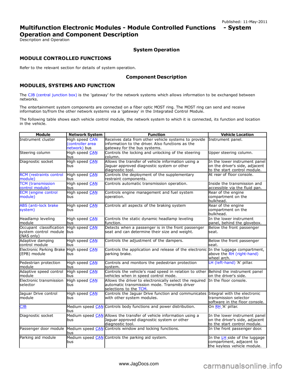
Instrument cluster
High speed CAN
(controller area network) bus Receives data from other vehicle systems to provide
information to the driver. Also functions as the gateway for the bus systems. Instrument panel. Steering column
High speed CAN bus Controls the locking and unlocking of the steering
column. Upper steering column. Diagnostic socket
High speed CAN bus Allows the transfer of vehicle information using a
Jaguar approved diagnostic system or other diagnostic tool. In the lower instrument panel
on the driver's side, adjacent
to the start control module. RCM (restraints control module) High speed CAN bus Controls the deployment of the supplementary
restraint components. At rear of floor console. TCM (transmission
control module) High speed CAN bus Controls automatic transmission operation.
Inside the transmission and
accessible via the fluid pan. ECM (engine control
module) High speed CAN bus Controls engine management and fuel system
operation. Rear of the engine
compartment on the
bulkhead. ABS (anti-lock brake
system) High speed CAN bus Controls all aspects of the braking system
Rear of the engine
compartment on the
bulkhead. Headlamp leveling
module High speed CAN bus Controls the static dynamic headlamp leveling
function. In the lower instrument panel, behind the glovebox. Occupant classification
system control module (NAS only) High speed CAN bus Detects when a passenger is in the front passenger
seat and can determine their size and weight. Below the front passenger
seat. Adaptive damping
control module High speed CAN bus Controls the adjustment of the dampers.
Below the front passenger
seat. Electronic Parking Brake
(EPB) module High speed CAN bus Controls the application and release of the electronic
parking brake. In the luggage compartment,
above the RH (right-hand)
wheel arch. Pedestrian protection
module High speed CAN bus Controls and monitors the pedestrian protection system. LH (left-hand) 'A' pillar. Adaptive speed control
module High speed CAN bus Controls the vehicle's road speed in relation to other
vehicles when in speed control mode. Behind the instrument panel
on the driver's side. Electronic transmission
selector High speed CAN bus Allows the driver to electronically select the required
automatic transmission mode. Transmits driver
selections to the TCM. In the floor console. Jaguar Drive control
module High speed CAN bus Controls the Jaguar Drive function and communicates
with other system modules. Integral with the electronic
transmission selector
software in the floor console. CJB
Medium speed CAN bus Controls body functions and power distribution. On RH 'A' pillar. Diagnostic socket
Medium speed CAN bus Allows the transfer of vehicle information using a
Jaguar approved diagnostic system or other diagnostic tool. In the lower instrument panel
on the driver's side, adjacent
to the start control module. Passenger door module
Medium speed CAN bus Controls window and locking functions. In the front passenger door. Parking aid module
Medium speed CAN bus Controls the parking aid system.
In the LH side of the luggage compartment, adjacent to
the keyless vehicle module. www.JagDocs.com
Page 2171 of 3039
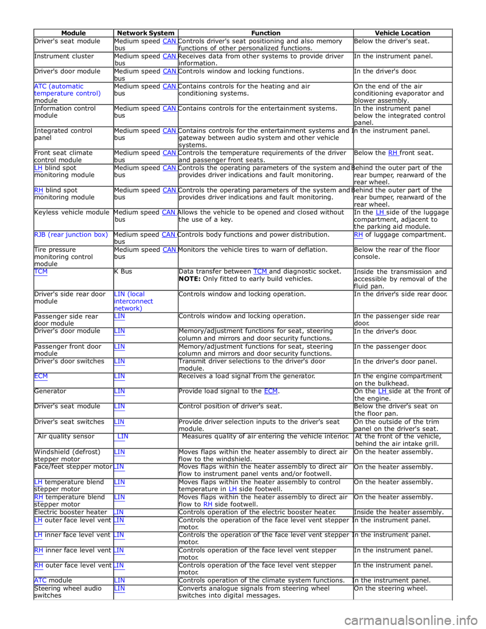
Module Network System Function Vehicle Location
Driver's seat module Medium speed CAN Controls driver's seat positioning and also memory Below the driver's seat. bus functions of other personalized functions.
Instrument cluster Medium speed CAN Receives data from other systems to provide driver In the instrument panel. bus information.
Driver's door module Medium speed CAN Controls window and locking functions. In the driver's door. bus
ATC (automatic Medium speed CAN Contains controls for the heating and air On the end of the air
temperature control)
module bus conditioning systems.
conditioning evaporator and
blower assembly.
Information control Medium speed CAN Contains controls for the entertainment systems. In the instrument panel module bus
below the integrated control
panel.
Integrated control Medium speed CAN Contains controls for the entertainment systems and In the instrument panel. panel bus
gateway between audio system and other vehicle
systems.
Front seat climate Medium speed CAN Controls the temperature requirements of the driver Below the RH front seat. control module bus and passenger front seats.
LH blind spot Medium speed CAN Controls the operating parameters of the system and Behind the outer part of the monitoring module bus provides driver indications and fault monitoring.
rear bumper, rearward of the
rear wheel.
RH blind spot Medium speed CAN Controls the operating parameters of the system and Behind the outer part of the monitoring module bus provides driver indications and fault monitoring.
rear bumper, rearward of the
rear wheel.
Keyless vehicle module Medium speed CAN Allows the vehicle to be opened and closed without In the LH side of the luggage bus the use of a key.
compartment, adjacent to
the parking aid module.
RJB (rear junction box) Medium speed CAN Controls body functions and power distribution. RH of luggage compartment. bus
Tire pressure Medium speed CAN Monitors the vehicle tires to warn of deflation. Below the rear of the floor monitoring control
module bus console.
TCM K Bus Data transfer between TCM and diagnostic socket. NOTE: Only fitted to early build vehicles. Inside the transmission and
accessible by removal of the
fluid pan.
Driver's side rear door
module LIN (local
interconnect
network) Controls window and locking operation. In the driver's side rear door.
Passenger side rear
door module LIN Controls window and locking operation. In the passenger side rear
door.
Driver's door module LIN Memory/adjustment functions for seat, steering
column and mirrors and door security functions. In the driver's door.
Passenger front door
module LIN Memory/adjustment functions for seat, steering
column and mirrors and door security functions. In the passenger door.
Driver's door switches LIN Transmit driver selections to the driver's door
module. In the driver's door panel.
ECM LIN Receives a load signal from the generator. In the engine compartment
on the bulkhead.
Generator LIN Provide load signal to the ECM. On the LH side at the front of the engine.
Driver's seat module LIN Control position of driver's seat. Below the driver's seat on
the floor pan.
Driver's seat switches LIN Provide driver selection inputs to the driver's seat
module. On the outside of the trim
panel on the driver's seat.
Air quality sensor LIN Measures quality of air entering the vehicle interior. At the front of the vehicle,
behind the air intake grill.
Windshield (defrost)
stepper motor LIN Moves flaps within the heater assembly to direct air
flow to the windshield. On the heater assembly.
Face/feet stepper motor LIN Moves flaps within the heater assembly to direct air
flow to instrument panel vents and/or footwell. On the heater assembly.
LH temperature blend
stepper motor
RH temperature blend
stepper motor LIN Moves flaps within the heater assembly to control
temperature in LH side footwell.
LIN Moves flaps within the heater assembly to direct air
flow to RH side footwell. On the heater assembly.
On the heater assembly.
Electric booster heater LIN Controls operation of the electric booster heater. Inside the heater assembly.
LH outer face level vent LIN Controls the operation of the face level vent stepper In the instrument panel.
motor.
LH inner face level vent LIN Controls the operation of the face level vent stepper In the instrument panel.
motor.
RH inner face level vent LIN Controls operation of the face level vent stepper
motor.
RH outer face level vent LIN Controls operation of the face level vent stepper
motor. In the instrument panel.
In the instrument panel.
ATC module LIN Controls operation of the climate system functions. In the instrument panel.
Steering wheel audio
switches LIN Converts analogue signals from steering wheel
switches into digital messages. On the steering wheel.