2010 JAGUAR XFR Parking
[x] Cancel search: ParkingPage 1785 of 3039
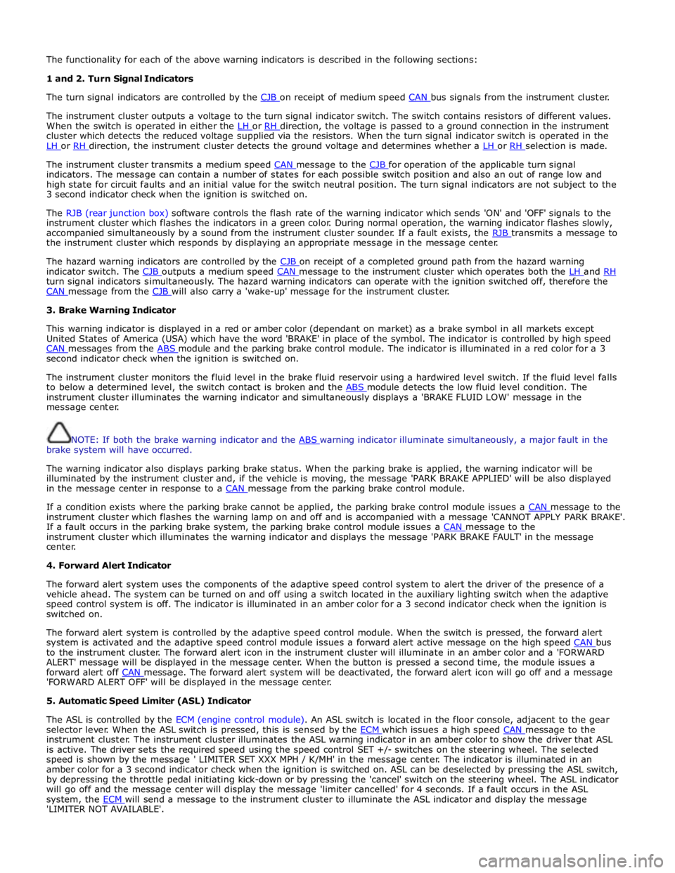
The functionality for each of the above warning indicators is described in the following sections:
1 and 2. Turn Signal Indicators
The turn signal indicators are controlled by the CJB on receipt of medium speed CAN bus signals from the instrument cluster.
The instrument cluster outputs a voltage to the turn signal indicator switch. The switch contains resistors of different values.
When the switch is operated in either the LH or RH direction, the voltage is passed to a ground connection in the instrument cluster which detects the reduced voltage supplied via the resistors. When the turn signal indicator switch is operated in the
LH or RH direction, the instrument cluster detects the ground voltage and determines whether a LH or RH selection is made.
The instrument cluster transmits a medium speed CAN message to the CJB for operation of the applicable turn signal indicators. The message can contain a number of states for each possible switch position and also an out of range low and
high state for circuit faults and an initial value for the switch neutral position. The turn signal indicators are not subject to the
3 second indicator check when the ignition is switched on.
The RJB (rear junction box) software controls the flash rate of the warning indicator which sends 'ON' and 'OFF' signals to the
instrument cluster which flashes the indicators in a green color. During normal operation, the warning indicator flashes slowly,
accompanied simultaneously by a sound from the instrument cluster sounder. If a fault exists, the RJB transmits a message to the instrument cluster which responds by displaying an appropriate message in the message center.
The hazard warning indicators are controlled by the CJB on receipt of a completed ground path from the hazard warning indicator switch. The CJB outputs a medium speed CAN message to the instrument cluster which operates both the LH and RH turn signal indicators simultaneously. The hazard warning indicators can operate with the ignition switched off, therefore the
CAN message from the CJB will also carry a 'wake-up' message for the instrument cluster. 3. Brake Warning Indicator
This warning indicator is displayed in a red or amber color (dependant on market) as a brake symbol in all markets except
United States of America (USA) which have the word 'BRAKE' in place of the symbol. The indicator is controlled by high speed
CAN messages from the ABS module and the parking brake control module. The indicator is illuminated in a red color for a 3 second indicator check when the ignition is switched on.
The instrument cluster monitors the fluid level in the brake fluid reservoir using a hardwired level switch. If the fluid level falls
to below a determined level, the switch contact is broken and the ABS module detects the low fluid level condition. The instrument cluster illuminates the warning indicator and simultaneously displays a 'BRAKE FLUID LOW' message in the
message center.
NOTE: If both the brake warning indicator and the ABS warning indicator illuminate simultaneously, a major fault in the brake system will have occurred.
The warning indicator also displays parking brake status. When the parking brake is applied, the warning indicator will be
illuminated by the instrument cluster and, if the vehicle is moving, the message 'PARK BRAKE APPLIED' will be also displayed
in the message center in response to a CAN message from the parking brake control module.
If a condition exists where the parking brake cannot be applied, the parking brake control module issues a CAN message to the instrument cluster which flashes the warning lamp on and off and is accompanied with a message 'CANNOT APPLY PARK BRAKE'.
If a fault occurs in the parking brake system, the parking brake control module issues a CAN message to the instrument cluster which illuminates the warning indicator and displays the message 'PARK BRAKE FAULT' in the message
center.
4. Forward Alert Indicator
The forward alert system uses the components of the adaptive speed control system to alert the driver of the presence of a
vehicle ahead. The system can be turned on and off using a switch located in the auxiliary lighting switch when the adaptive
speed control system is off. The indicator is illuminated in an amber color for a 3 second indicator check when the ignition is
switched on.
The forward alert system is controlled by the adaptive speed control module. When the switch is pressed, the forward alert
system is activated and the adaptive speed control module issues a forward alert active message on the high speed CAN bus to the instrument cluster. The forward alert icon in the instrument cluster will illuminate in an amber color and a 'FORWARD
ALERT' message will be displayed in the message center. When the button is pressed a second time, the module issues a
forward alert off CAN message. The forward alert system will be deactivated, the forward alert icon will go off and a message 'FORWARD ALERT OFF' will be displayed in the message center.
5. Automatic Speed Limiter (ASL) Indicator
The ASL is controlled by the ECM (engine control module). An ASL switch is located in the floor console, adjacent to the gear
selector lever. When the ASL switch is pressed, this is sensed by the ECM which issues a high speed CAN message to the instrument cluster. The instrument cluster illuminates the ASL warning indicator in an amber color to show the driver that ASL
is active. The driver sets the required speed using the speed control SET +/- switches on the steering wheel. The selected
speed is shown by the message ' LIMITER SET XXX MPH / K/MH' in the message center. The indicator is illuminated in an
amber color for a 3 second indicator check when the ignition is switched on. ASL can be deselected by pressing the ASL switch,
by depressing the throttle pedal initiating kick-down or by pressing the 'cancel' switch on the steering wheel. The ASL indicator
will go off and the message center will display the message 'limiter cancelled' for 4 seconds. If a fault occurs in the ASL
system, the ECM will send a message to the instrument cluster to illuminate the ASL indicator and display the message 'LIMITER NOT AVAILABLE'.
Page 1786 of 3039
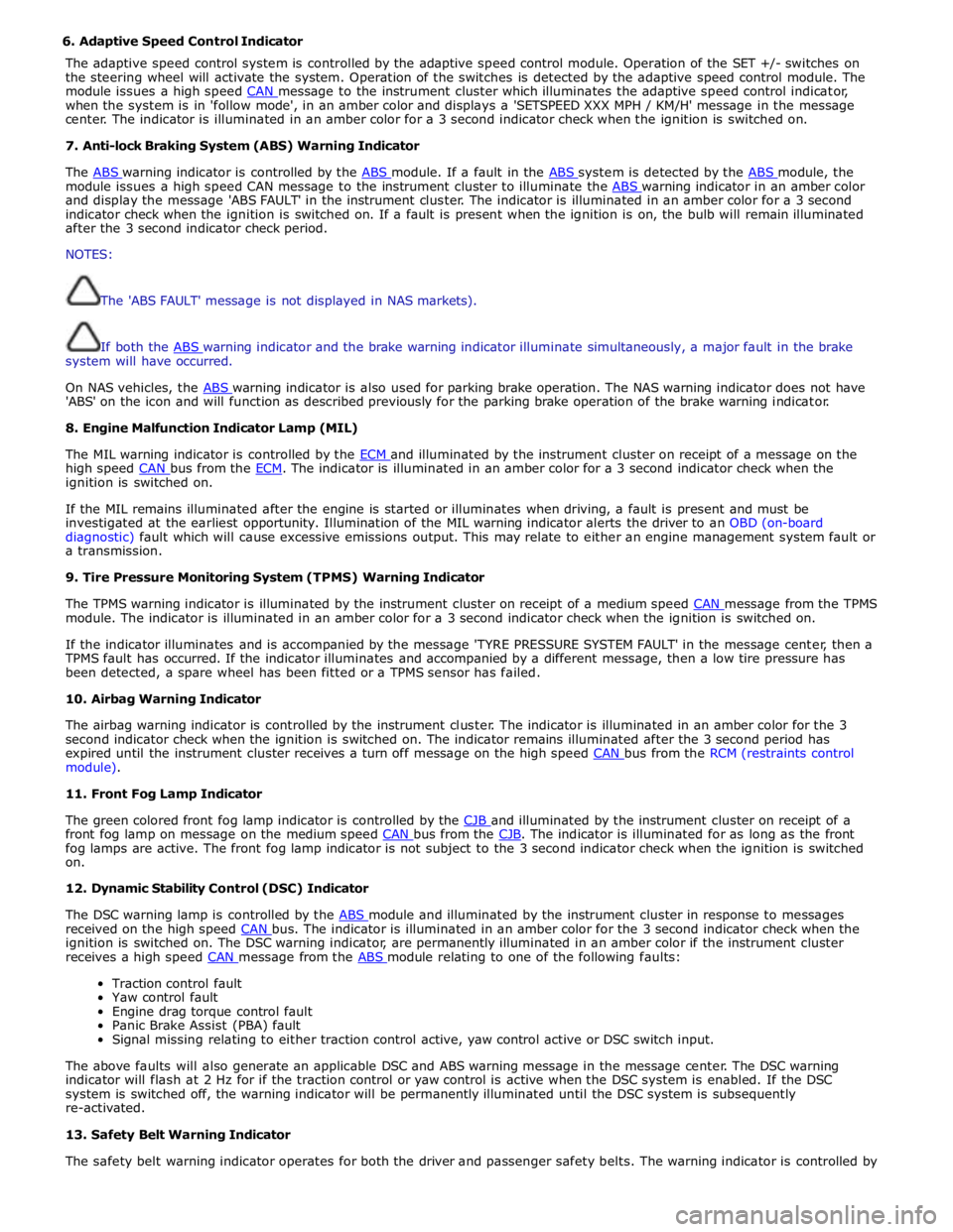
6. Adaptive Speed Control Indicator
The adaptive speed control system is controlled by the adaptive speed control module. Operation of the SET +/- switches on
the steering wheel will activate the system. Operation of the switches is detected by the adaptive speed control module. The
module issues a high speed CAN message to the instrument cluster which illuminates the adaptive speed control indicator, when the system is in 'follow mode', in an amber color and displays a 'SETSPEED XXX MPH / KM/H' message in the message
center. The indicator is illuminated in an amber color for a 3 second indicator check when the ignition is switched on.
7. Anti-lock Braking System (ABS) Warning Indicator
The ABS warning indicator is controlled by the ABS module. If a fault in the ABS system is detected by the ABS module, the module issues a high speed CAN message to the instrument cluster to illuminate the ABS warning indicator in an amber color and display the message 'ABS FAULT' in the instrument cluster. The indicator is illuminated in an amber color for a 3 second
indicator check when the ignition is switched on. If a fault is present when the ignition is on, the bulb will remain illuminated
after the 3 second indicator check period.
NOTES:
The 'ABS FAULT' message is not displayed in NAS markets).
If both the ABS warning indicator and the brake warning indicator illuminate simultaneously, a major fault in the brake system will have occurred.
On NAS vehicles, the ABS warning indicator is also used for parking brake operation. The NAS warning indicator does not have 'ABS' on the icon and will function as described previously for the parking brake operation of the brake warning indicator.
8. Engine Malfunction Indicator Lamp (MIL)
The MIL warning indicator is controlled by the ECM and illuminated by the instrument cluster on receipt of a message on the high speed CAN bus from the ECM. The indicator is illuminated in an amber color for a 3 second indicator check when the ignition is switched on.
If the MIL remains illuminated after the engine is started or illuminates when driving, a fault is present and must be
investigated at the earliest opportunity. Illumination of the MIL warning indicator alerts the driver to an OBD (on-board
diagnostic) fault which will cause excessive emissions output. This may relate to either an engine management system fault or
a transmission.
9. Tire Pressure Monitoring System (TPMS) Warning Indicator
The TPMS warning indicator is illuminated by the instrument cluster on receipt of a medium speed CAN message from the TPMS module. The indicator is illuminated in an amber color for a 3 second indicator check when the ignition is switched on.
If the indicator illuminates and is accompanied by the message 'TYRE PRESSURE SYSTEM FAULT' in the message center, then a
TPMS fault has occurred. If the indicator illuminates and accompanied by a different message, then a low tire pressure has
been detected, a spare wheel has been fitted or a TPMS sensor has failed.
10. Airbag Warning Indicator
The airbag warning indicator is controlled by the instrument cluster. The indicator is illuminated in an amber color for the 3
second indicator check when the ignition is switched on. The indicator remains illuminated after the 3 second period has
expired until the instrument cluster receives a turn off message on the high speed CAN bus from the RCM (restraints control module).
11. Front Fog Lamp Indicator
The green colored front fog lamp indicator is controlled by the CJB and illuminated by the instrument cluster on receipt of a front fog lamp on message on the medium speed CAN bus from the CJB. The indicator is illuminated for as long as the front fog lamps are active. The front fog lamp indicator is not subject to the 3 second indicator check when the ignition is switched
on.
12. Dynamic Stability Control (DSC) Indicator
The DSC warning lamp is controlled by the ABS module and illuminated by the instrument cluster in response to messages received on the high speed CAN bus. The indicator is illuminated in an amber color for the 3 second indicator check when the ignition is switched on. The DSC warning indicator, are permanently illuminated in an amber color if the instrument cluster
receives a high speed CAN message from the ABS module relating to one of the following faults:
Traction control fault
Yaw control fault
Engine drag torque control fault
Panic Brake Assist (PBA) fault
Signal missing relating to either traction control active, yaw control active or DSC switch input.
The above faults will also generate an applicable DSC and ABS warning message in the message center. The DSC warning
indicator will flash at 2 Hz for if the traction control or yaw control is active when the DSC system is enabled. If the DSC
system is switched off, the warning indicator will be permanently illuminated until the DSC system is subsequently
re-activated.
13. Safety Belt Warning Indicator
The safety belt warning indicator operates for both the driver and passenger safety belts. The warning indicator is controlled by
Page 1804 of 3039

DTC Description Possible Cause Action B1D3615
Turn Indicator
Switch
Direction indicator switch
circuit - short to power, open
circuit Carry out any pinpoint tests associated with this DTC using
the manufacturer approved diagnostic system. Refer to the
electrical circuit diagrams and check direction indicator
switch circuit for short to power, open circuit B1D3711
Wiper Switch
Connection Circuit
Flick wipe switch circuit - short
to ground Refer to the electrical circuit diagrams and check flick wipe
switch circuit for short to ground B1D3715
Wiper Switch
Connection Circuit
Flick wipe switch circuit - short
to power, open circuit Carry out any pinpoint tests associated with this DTC using
the manufacturer approved diagnostic system. Refer to the
electrical circuit diagrams and check flick wipe switch circuit
for short to power, open circuit C111064
Power steering
Calibration Data
Invalid VAPS curve loaded Re-configure the instrument cluster as new to download
VAPS curve data P063511
Power Steering
Control Circuit
VAPS ignition supply circuit -
short to ground Refer to the electrical circuit diagrams and check VAPS
ignition supply circuit for short to ground P063512
Power Steering
Control Circuit
VAPS ignition supply circuit -
short to power Refer to the electrical circuit diagrams and check VAPS
ignition supply circuit for short to power P063513
Power Steering
Control Circuit
VAPS ignition supply circuit -
open circuit Refer to the electrical circuit diagrams and check VAPS
ignition supply circuit for open circuit P063522
Power Steering
Control Circuit
First valid received speed
value above threshold Check ABS module for DTCs and refer to relevant DTC Index P063544
Power Steering
Control Circuit
Data memory failure Re-configure the instrument cluster as new to download
VAPS curve data U000188
High Speed CAN
Communication
Bus
Bus Off Carry out any pinpoint tests associated with this DTC using
the manufacturer approved diagnostic system. Carry out CAN
network integrity test using the manufacturer approved
diagnostic system. Refer to the electrical circuit diagrams
and check HS CAN network to instrument cluster U001088
Medium Speed
CAN
Communication
Bus
Bus Off Carry out any pinpoint tests associated with this DTC using
the manufacturer approved diagnostic system. Carry out CAN
network integrity test using the manufacturer approved
diagnostic system. Refer to the electrical circuit diagrams
and check MS CAN network to instrument cluster U010000
Lost
Communication
With ECM/PCM “A”
Loss of CAN communication
with ECM Carry out any pinpoint tests associated with this DTC using
the manufacturer approved diagnostic system. Check ECM for
DTCs and refer to the relevant DTC Index U010100
Lost
Communication
with TCM
Loss of CAN communication
with TCM Carry out any pinpoint tests associated with this DTC using
the manufacturer approved diagnostic system. Check TCM for
DTCs and refer to the relevant DTC Index U010300
Lost
Communication
With Gear Shift
Module
Loss of CAN communication
with transmission shift module Carry out any pinpoint tests associated with this DTC using
the manufacturer approved diagnostic system. Check
transmission shift module for DTCs and refer to the relevant
DTC Index U010400
Lost
Communication
With Cruise
Control Module
Loss of CAN communication
with speed control module Carry out any pinpoint tests associated with this DTC using
the manufacturer approved diagnostic system. Check speed
control module for DTCs and refer to the relevant DTC Index U012100
Lost
Communication
With Anti-Lock
Brake System
(ABS) Control
Module
Loss of CAN communication
with ABS module Carry out any pinpoint tests associated with this DTC using
the manufacturer approved diagnostic system. Check ABS
module for DTCs and refer to the relevant DTC Index U012700
Lost
Communication
With Tire
Pressure Monitor
Module
Loss of CAN communication
with tire pressure monitoring
module Carry out any pinpoint tests associated with this DTC using
the manufacturer approved diagnostic system. Check tire
pressure monitoring module for DTCs and refer to the
relevant DTC Index U012800 Lost
Loss of CAN communication Carry out any pinpoint tests associated with this DTC using Communication the manufacturer approved diagnostic system. Check parking With Park Brake with parking brake module
brake module for DTCs and refer to the relevant DTC Index Control Module
Page 1823 of 3039
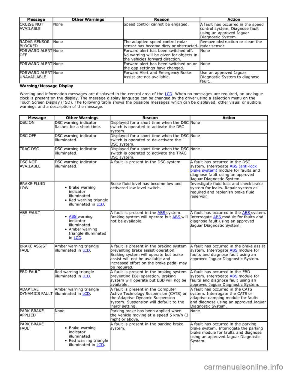
Message Other Warnings Reason Action CRUISE NOT
AVAILABLE None Speed control cannot be engaged.
A fault has occurred in the speed
control system. Diagnose fault
using an approved Jaguar Diagnostic System. RADAR SENSOR
BLOCKED None
The adaptive speed control radar
sensor has become dirty or obstructed. Remove obstruction or clean the
radar sensor. FORWARD ALERT
OFF None
Forward alert has been switched off.
No warning will be given for objects in
the vehicles forward direction. None FORWARD ALERT None
Forward alert has been switched on or
the gap settings have changed. None FORWARD ALERT
UNAVAILABLE None
Forward Alert and Emergency Brake
Assist are not available. Use an approved Jaguar
Diagnostic System to diagnose
fault.. Warning/Message Display
Warning and information messages are displayed in the central area of the LCD. When no messages are required, an analogue clock is present on the display. The message display language can be changed by the driver using a selection menu on the
Touch Screen Display (TSD). The following table shows the possible messages which can be displayed, other visual or audible
warnings and a description of the message.
Message Other Warnings Reason Action DSC ON
DSC warning indicator
flashes for a short time. Displayed for a short time when the DSC
switch is operated to activate the DSC system. None DSC OFF
DSC warning indicator
illuminated. Displayed for a short time when the DSC
switch is operated to de-activate the
DSC system. None TRAC DSC
DSC warning indicator
illuminated. Displayed for a short time when the DSC
switch is operated to activate the TRAC
DSC system. None DSC NOT
AVAILABLE DSC warning indicator
illuminated. A fault is present in the DSC system.
A fault has occurred in the DSC
system. Interrogate ABS (anti-lock
brake system) module for faults and
diagnose fault using an approved Jaguar Diagnostic System. BRAKE FLUID
LOW
Brake warning
indicator
illuminated.
Red warning triangle
illuminated in LCD. Brake fluid level has become low and
activated low level switch. Investigate fluid loss and check brake
system for leaks. Repair system as
required and replenish brake fluid
reservoir. ABS FAULT
ABS warning indicator
illuminated.
Amber warning
triangle illuminated
in LCD. A fault is present in the ABS system. Braking system will operate but ABS will not be available. A fault has occurred in the ABS system. Interrogate ABS module for faults and diagnose fault using an approved
Jaguar Diagnostic System. BRAKE ASSIST
FAULT Amber warning triangle
illuminated in LCD. A fault is present in the braking system
preventing brake assist operation.
Braking system will operate but brake
assist will not be available and
increased effort on the brake pedal may
be required. A fault has occurred in the brake assist
system. Interrogate ABS module for faults and diagnose fault using an
approved Jaguar Diagnostic System. EBD FAULT
Red warning triangle
illuminated in LCD. A fault is present in the braking system
preventing EBD operation. Braking
system will operate but EBD will not be
available. A fault has occurred in the EBD
system. Interrogate ABS module for faults and diagnose fault using an approved Jaguar Diagnostic System. ADAPTIVE
DYNAMICS FAULT Amber warning triangle
illuminated in LCD. A fault is present in the Computer
Active Technology Suspension (CATS) or
the Adaptive Dynamic Suspension
system. Suspension will default to the
'hard' setting. A fault has occurred in the CATS
system. Interrogate the CATS or
adaptive damping module for faults
and diagnose using an approved Jaguar Diagnostic System. PARK BRAKE
APPLIED None
Parking brake has been applied when
the vehicle moving at a speed 5 km/h (3 mph) or above. None PARK BRAKE
FAULT
Brake warning
indicator
illuminated.
Red warning triangle
illuminated in LCD. A fault is present in the parking brake
system. A fault has occurred in the parking
brake system. Interrogate the parking
brake module for faults and diagnose
using an approved Jaguar Diagnostic
System.
Page 1824 of 3039

Message Other Warnings Reason Action APPLY FOOT AND
PARK BRAKE Amber warning triangle
illuminated in LCD. The battery has been disconnected or
power supply interrupted to the parking
brake module. Apply foot brake and parking brake to
reset the parking brake module. CANNOT APPLY
PARK BRAKE
Brake warning
indicator flashing.
Red warning triangle
illuminated in LCD. NOTE: In certain
markets the brake
warning indicator
does not flash. A fault is present in the parking brake
system and the parking brake cannot be
applied. A fault has occurred in the parking
brake system. Interrogate the parking
brake module for faults and diagnose
using an approved Jaguar Diagnostic
System. CHECK TYRE
PRESSURE
Tire Pressure
Monitoring System
(TPMS) warning
indicator
illuminated.
Vehicle graphic
displaying tire
location. A tire pressure has decreased to below
the warning threshold. Check tires for punctures and re-inflate
to correct pressures. TYRE NOT
MONITORED
Tire Pressure
Monitoring System
(TPMS) warning
indicator
illuminated.
Vehicle graphic
displaying tire
location.
One or more tire pressure
sensors have developed a fault.
A temporary spare wheel or a
wheel without a sensor has been
fitted at the displayed position.
An unapproved accessory may be
interfering with the TPMS.
Check for local RF interference.
A wheel has been fitted without
a TPMS sensor fitted (space
saver spare wheel).
TPMS sensor has developed a
fault or the battery voltage is
low.
A fault has occurred in the
TPMS. Interrogate the TPMS
module for faults and diagnose
using an approved Jaguar
Diagnostic System. CHECK ALL TYRE
PRESSURES
Tire Pressure
Monitoring System
(TPMS) warning
indicator
illuminated.
Amber warning
triangle illuminated
in LCD. Vehicle graphic
displaying tire
location. One or more tire pressures have
decreased to below the warning
threshold.
Check tires for punctures and
re-inflate to correct pressures.
Message may be displayed
when TPMS is learning position
of a new sensor. TYRE PRESSURE
SYSTEM FAULT
Tire Pressure
Monitoring System
(TPMS) warning
indicator
illuminated.
Amber warning
triangle illuminated
in LCD.
Wheels and tires without sensors
have been fitted to the vehicle.
TPMS sensors have become
defective.
An unapproved accessory may be
interfering with the TPMS.
A fault is present in the TPMS
system and the tire pressures
cannot be monitored. A fault has occurred in the TPMS.
Interrogate the TPMS module for faults
and diagnose using an approved Jaguar
Diagnostic System. TYRE PRESSURE
LOW FOR SPEED
Tire Pressure
Monitoring System
(TPMS) warning
indicator
illuminated.
Amber warning
triangle illuminated
in LCD. TPMS has detected current tire
pressures are too low for sustained high
speed driving Check tire pressures and inflate to the
correct pressures if necessary. TYRE PRESSURE
SYSTEM FAULT
Tire Pressure
Monitoring System
(TPMS) warning
indicator
illuminated.
Amber warning
triangle illuminated
Wheels and tires without sensors
have been fitted to the vehicle.
TPMS sensors have become
defective.
An unapproved accessory may be
interfering with the TPMS.
A fault is present in the TPMS A fault has occurred in the TPMS.
Interrogate the TPMS module for faults
and diagnose using an approved Jaguar
Diagnostic System.
Page 1840 of 3039
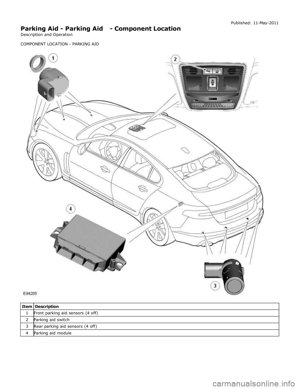
Parking Aid - Parking Aid - Component Location
Description and Operation
COMPONENT LOCATION - PARKING AID Published: 11-May-2011
Item Description 1 Front parking aid sensors (4 off) 2 Parking aid switch 3 Rear parking aid sensors (4 off) 4 Parking aid module
Page 1841 of 3039
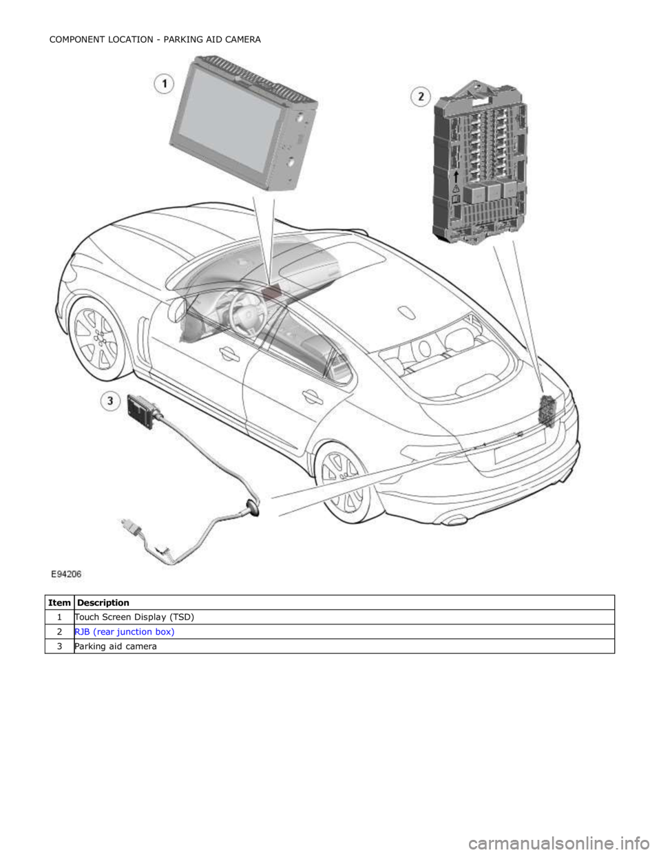
1 Touch Screen Display (TSD) 2 RJB (rear junction box) 3 Parking aid camera COMPONENT LOCATION - PARKING AID CAMERA
Page 1842 of 3039

Parking Aid - Parking Aid - Overview
Description and Operation
OVERVIEW Published: 11-May-2011
The parking aid system provides an audible warning to the driver when any obstacles are in the path of the vehicle during a
forward (if front sensors are fitted) or reversing manoeuver. The purpose of the system is to assist the driver when parking or
manoeuvring in a restricted space. It is not designed as a crash avoidance system or a replacement for visual interpretation by
the driver.
All vehicles are fitted with rear parking aid sensors. Higher specification vehicles may also be fitted with front parking aid
sensors.
A roof console mounted parking aid switch allows the driver to deactivate the parking aid system if operation is not required.
NOTE: The switch is only fitted to vehicles with front parking aid sensors.
A parking aid camera is a standard fitment on some models and optional on others. The parking aid camera supplements the
information provided by the parking aid system by providing the driver with a visual display of the area directly behind the
vehicle.
www.JagDocs.com