Page 1986 of 3039

System Operation
The Televis ion s ys tem has various l evels of us er cont rol t hrough the Touch-s creen, ICP (int egrated control panel) and
s teeri ng wheel control panel. The s ys tem includes nine analogue and nine di git al cha nnel pre-s et s . As wit h t he audio
s ys t em, the us er can s earch up or down and s tore by a l ong pres s of the s elect ed cha nnel but ton. The s ys t em offers a
choi ce of screen as pect rati os s imi lar t o a t ypi cal domes ti c receiver, givi ng opt ions bet ween the s t andard 4:3 format, wi de
s creen 16:9 format and zoom to fil l the screen.
To provide the s t rongest pos s ible si gnal t he Televis ion t uner recei ves s i gnal s from 4 ant enna s ources l ocat ed in the
heat ed rear wi ndow. Unl ike domes ti c s ys t ems t hi s s yst em gi ves a more progres s ive pict ure l oss if t he s ignal i s los t . The
s ignal los s is i ndicat ed t o t he user by a ‘los s of recepti on’ s creen mes s age.
The Televis ion s ys tem is primaril y cont rol led from the Touch-s creen and t he ICP (i nt egrat ed cont rol panel ) which are
located i n t he cent er of the i nst rument panel. Control s i gnals from t he Touch-screen di s pl ay are sent on t he MOST (media
ori ent ed s yst ems t rans port ) ri ng to the Televis i on tuner. The Televis i on tuner uses a dedi cat ed CVBS (compos it e video
s ignal) bus t o t ransmit video s i gnals to the Touch-s creen.
Control s i gnals from t he ICP (Integrat ed control panel) are rel ayed on the medi um s peed CAN bus t o t he ICM (i nformati on
cont rol module). The ICM (i nformati on cont rol module) rel ays the control s i gnal s to the Tel evi si on tuner on t he MOST
(medi a oriented s ys tems trans port ) ri ng. The ICM (i nformat ion control modul e) is t he t imi ng mas ter for the MOST (medi a
ori ent ed s yst ems t rans port ) ri ng and als o host s a gat eway functi on between t he medium s peed CAN bus and the MOST
(medi a oriented s ys tems trans port ) ri ng.
Dependi ng upon the audio sys tem vers ion fit ted the Televis i on tuner audi o output s ignals are s ent on the MOST (medi a
ori ent ed s yst ems t rans port ) ri ng to the IAM (int egrated audi o module) or the power a mpli fi er for s peaker out put.
Component Description
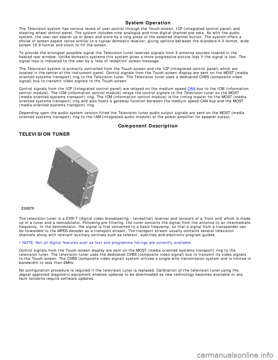
TELEVISION TUNERThe t el evi s ion t uner i s a DVB-T (di git al vi deo broadcas ti ng - terres trial ) receiver and cons is ts of a 'front end' whi ch is made
up of a t uner and a demodul at or. Foll owing pre-fi lt eri ng, t he t uner converts t he s ignal from t he antenna t o an i nt ermedi ate
frequency. In t he demodulator, the si gnal i s fi rs t convert ed t o a bas ic frequency, s o t hat a s ignal from a t rans ponder can
be forwarded t o t he MPEG decoder as a trans port s t ream. The t rans port s tream us ual ly contai ns several t el evi s ion
channels al ong wit h rel evant auxili ary s ervi ces s uch as t eletext , subt it les and electronic program guides .
• NOTE: Not all digi tal feat ures s uch as text and programme l is ti ngs are currentl y a vai lable.
Control s i gnals from t he Touch-screen di s pl ay are sent on t he MOST (media orient ed sys t ems transport) ring t o t he
t el evi s ion t uner. The tel evi si on tuner us es the dedicated CVBS (composi te vi deo s ignal) bus t o transmit i ts vi deo si gnal s
t o the Touch-s creen. The CVBS (composi te video s ignal) s yst em ut il izes a s i ngl e wire t rans mis s ion sys tem and is limit ed in
bandwi dth to l ess than 6MHz.
No confi gurati on procedure is required if t he tel evi si on t uner is replaced. Cal ibrat ion of t he t el evi s ion t uner us ing t he
Jaguar approved di agnos t ic equipment enabl es updat es to be downl oaded as new technol ogy becomes availabl e or any
faul t concerns require s oft ware updat es .
Page 1988 of 3039
1
2
3 frequency) si gnal s. The pos it ive fil ter i s pres ent on al l vehi cl e t ypes and market s .
The ri ght hand s i de doubl e coi l RF (radio frequency) filt er is onl y used in conjunct ion wit h t he tel evi si on antenna modules
and is connect ed acros s the heat ed rear wi ndow ground ci rcuit . If a tel evi si on s ys t e m i s not fi tt ed a fil ter i s used whi ch is
li nked di rectl y t o ground.
Touch-ScreenItemDescription
Touch-s creen
Touch-s creen on/off but ton
Home menu butt on
The Touch-screen i s t he pri mary us er int erface for the t elevis ion sys tem. From t he 'Home' s creen menu t elevis ion is a
s ub-menu of 'Audio'. The Touch-s creen communicates wi th the t elevis ion tuner. Vi deo si gnal s to the Touch-s creen are
t ransmit ted from t he tel evi si on t uner.
Integrated Control Panel
Page 1989 of 3039

1
2
3
4
5
6
1
2
3
4Touch-s creen
Seek up but ton
Set ti ngs but ton
O n/off and volume cont rol
Source but ton
Seek down but ton
The ICP (i ntegrat ed cont rol panel ) dupl icates many of t he Touch-s creen tel evi si on user control features . The ICP
(integrat ed cont rol panel) communicates wi th the televis i on sys t em t hrough the medium speed CAN and MOST (medi a
ori ent ated sys tems trans port ) bus s ys t ems .
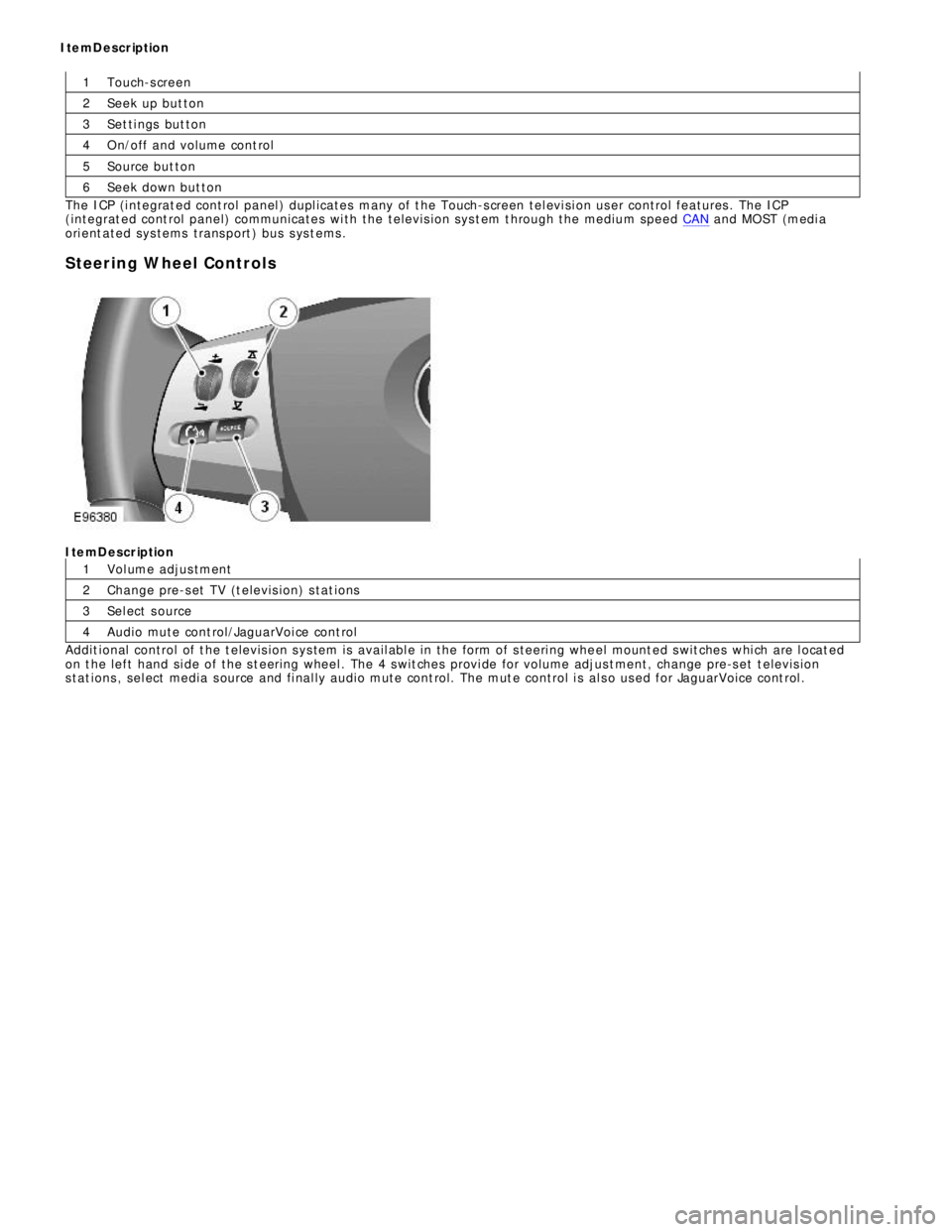
Steering Wheel ControlsItemDescription
Vol ume adjus tment
Change pre-s et TV (t elevis ion) s tat ions
Sel ect s ource
Audio mute cont rol/JaguarVoi ce cont rol
Addit ional control of t he t elevis ion s ys tem is avail abl e in the form of s teeri ng whe el mount ed s wit ches whi ch are l ocat ed
on t he left hand si de of the s t eering wheel . The 4 s wit ches provi de for volume adjus t ment, change pre-s et t elevis ion
s tat ions , sel ect media s ource and fi nal ly audio mute cont rol. The mut e control i s al s o us ed for JaguarVoice cont rol . ItemDescription
Page 1991 of 3039
Information and Entertainment System - Audio Unit
Removal and Installation
Removal
NOTE: Removal steps in this procedure may contain installation details. Published: 05-Apr-2013
1. Refer to: Battery Disconnect and Connect (414-01 Battery, Mounting and Cables, General Procedures).
2. Refer to: Audio and Climate Control Assembly (415-01A Information and Entertainment System, Removal and Installation).
3. CAUTION: Protect the surrounding trim to avoid
damage.
4. CAUTION: Cover fiber optic cable connectors to
minimize dust ingress and avoid bending the cables in a
radius of less than 30 mm.
Page 1993 of 3039
Published: 11-May-2011
Information and Entertainment System - Audio Unit Antenna Amplifier
Removal and Installation
Removal
NOTE: Removal steps in this procedure may contain installation details.
1. Refer to: Battery Disconnect and Connect (414-01 Battery, Mounting and Cables, General Procedures).
2. Refer to: C-Pillar Trim Panel (501-05 Interior Trim and Ornamentation, Removal and Installation).
Installation
3. Torque: 10 Nm
4.
1. To install, reverse the removal procedure.
Page 1994 of 3039
Published: 11-May-2011
Information and Entertainment System - Audio and Climate Control Assembly
Removal and Installation
Removal
NOTE: Removal steps in this procedure may contain installation details.
1. Remove both floor console side trim panels.
Refer to: Floor Console Side Trim Panel (501-12 Instrument Panel and Console, Removal and Installation).
Installation
2. Torque: 4 Nm
1. To install, reverse the removal procedure.
Page 1998 of 3039
Published: 11-May-2011
Information and Entertainment System - Information and Entertainment Module
Removal and Installation
Removal
NOTE: Removal steps in this procedure may contain installation details.
1. Refer to: Battery Disconnect and Connect (414-01 Battery, Mounting and Cables, General Procedures).
2. Refer to: Audio Unit (415-01A Information and Entertainment System, Removal and Installation).
Installation
3. Torque: 3 Nm
1. NOTE: New units must be configured using the Programmable
Module Installation Routine in the diagnostic tool.
To install, reverse the removal procedure.
Page 2001 of 3039
Published: 11-May-2011
Information and Entertainment System - Steering Wheel Audio Controls
Removal and Installation
Removal
NOTE: Removal steps in this procedure may contain installation details.
1. Make the SRS system safe.
Refer to: Standard Workshop Practices (100-00 General Information, Description and Operation).
2. Refer to: Driver Air Bag Module (501-20B Supplemental Restraint System, Removal and Installation).
3. Refer to: Upshift Paddle Switch (307-05A Automatic Transmission/Transaxle External Controls - V6 3.0L Petrol, Removal and
Installation).
4. Refer to: Downshift Paddle Switch (307-05A Automatic Transmission/Transaxle External Controls - V6 3.0L Petrol, Removal and
Installation).
5. Torque: 3 Nm 6. Torque: 3 Nm