2010 JAGUAR XFR audio
[x] Cancel search: audioPage 2018 of 3039
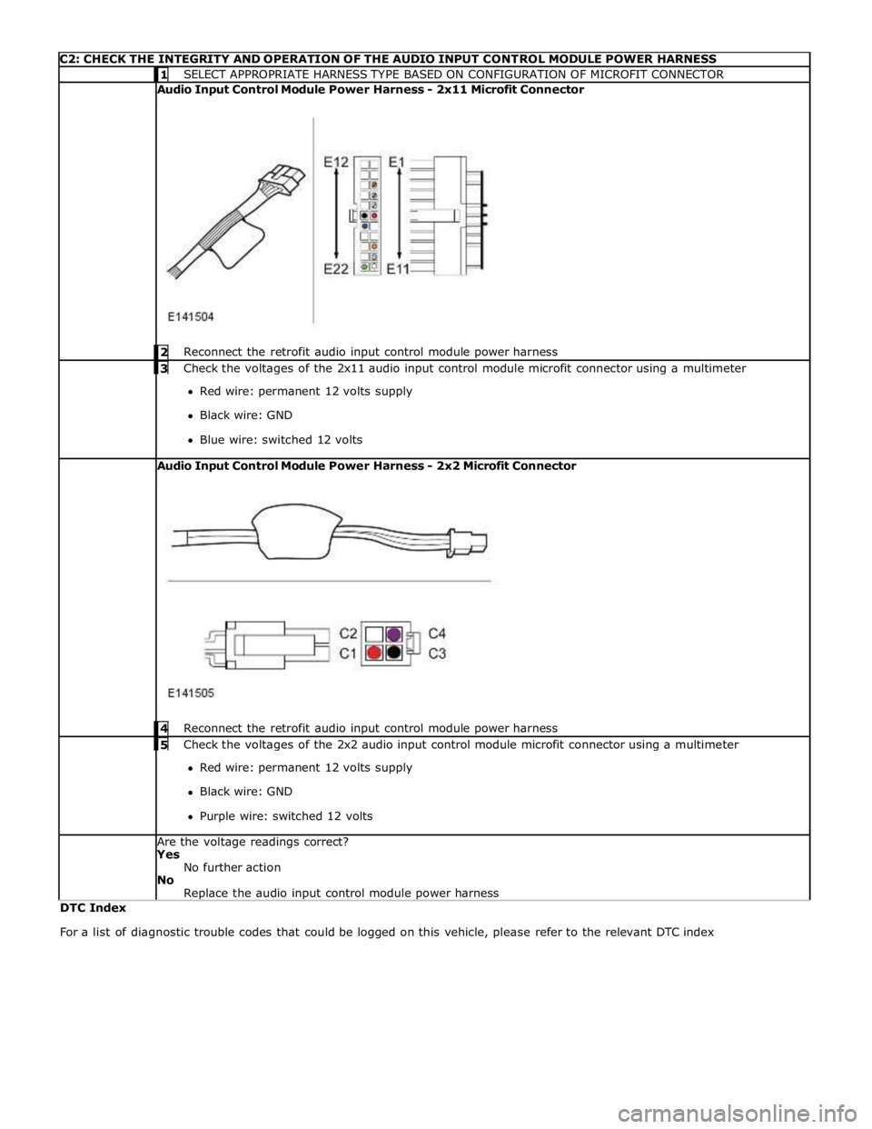
C2: CHECK THE INTEGRITY AND OPERATION OF THE AUDIO INPUT CONTROL MODULE POWER HARNESS 1 SELECT APPROPRIATE HARNESS TYPE BASED ON CONFIGURATION OF MICROFIT CONNECTOR Audio Input Control Module Power Harness - 2x11 Microfit Connector
2 Reconnect the retrofit audio input control module power harness 3 Check the voltages of the 2x11 audio input control module microfit connector using a multimeter Red wire: permanent 12 volts supply
Black wire: GND
Blue wire: switched 12 volts Audio Input Control Module Power Harness - 2x2 Microfit Connector
4 Reconnect the retrofit audio input control module power harness 5 Check the voltages of the 2x2 audio input control module microfit connector using a multimeter Red wire: permanent 12 volts supply
Black wire: GND
Purple wire: switched 12 volts Are the voltage readings correct?
Yes
No further action
No
Replace the audio input control module power harness DTC Index
For a list of diagnostic trouble codes that could be logged on this vehicle, please refer to the relevant DTC index
Page 2069 of 3039

5 RJB (rear junction box) 6 Battery monitoring system module 7 Rear view camera 8 TCM (transmission control module) 9 Generator 10 Driver's door switch pack 11 Rear door control module 12 Driver's door control module 13 ECM (engine control module) 14 Electronic transmission selector 15 Driver's seat module 16 Driver's seat switch pack 17 Rear door control module 18 Front passenger door control module 19 Clockspring 20 Audio and telephone steering wheel switches 21 Instrument cluster 22 Start control module
Page 2073 of 3039
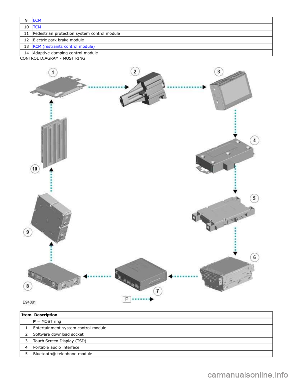
10 TCM 11 Pedestrian protection system control module 12 Electric park brake module 13 RCM (restraints control module) 14 Adaptive damping control module CONTROL DIAGRAM - MOST RING
Item Description P = MOST ring 1 Entertainment system control module 2 Software download socket 3 Touch Screen Display (TSD) 4 Portable audio interface 5 Bluetooth® telephone module
Page 2074 of 3039

7 Multi-media module 8 DAB/SDARS receiver 9 Television (TV) tuner 10 Audio system amplifier
OPERATION System Operation
Refer to the relevant system section for details of system operation.
DESCRIPTION Component Description
Refer to the relevant system section for details of system description.
Page 2077 of 3039
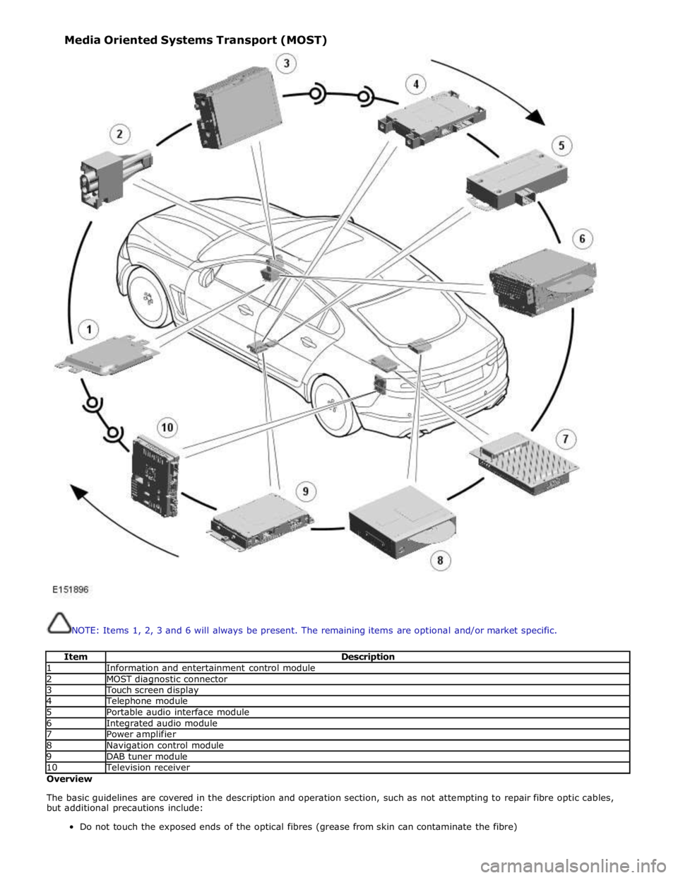
NOTE: Items 1, 2, 3 and 6 will always be present. The remaining items are optional and/or market specific.
Item Description 1 Information and entertainment control module 2 MOST diagnostic connector 3 Touch screen display 4 Telephone module 5 Portable audio interface module 6 Integrated audio module 7 Power amplifier 8 Navigation control module 9 DAB tuner module 10 Television receiver Overview
The basic guidelines are covered in the description and operation section, such as not attempting to repair fibre optic cables,
but additional precautions include:
Do not touch the exposed ends of the optical fibres (grease from skin can contaminate the fibre) Media Oriented Systems Transport (MOST)
Page 2080 of 3039
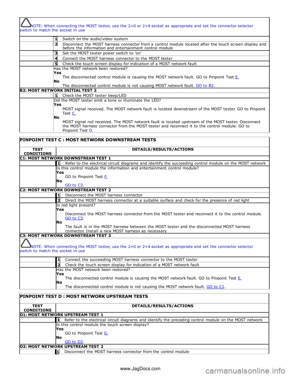
NOTE: When connecting the MOST tester, use the 2+0 or 2+4 socket as appropriate and set the connector selector
switch to match the socket in use 1 Switch on the audio/video system 2 Disconnect the MOST harness connector from a control module located after the touch screen display and before the information and entertainment control module 3 Set the MOST tester power switch to 'on' 4 Connect the MOST harness connector to the MOST tester 5 Check the touch screen display for indication of a MOST network fault Has the MOST network been restored? Yes
The disconnected control module is causing the MOST network fault. GO to Pinpoint Test E. No
The disconnected control module is not causing MOST network fault. GO to B2. B2: MOST NETWORK INITIAL TEST 2 1 Check the MOST tester beep/LED Did the MOST tester emit a tone or illuminate the LED? Yes
MOST signal received. The MOST network fault is located downstream of the MOST tester. GO to Pinpoint
Test C. No
MOST signal not received. The MOST network fault is located upstream of the MOST tester. Disconnect
the MOST harness connector from the MOST tester and reconnect it to the control module. GO to Pinpoint Test D.
PINPOINT TEST C : MOST NETWORK DOWNSTREAM TESTS TEST
CONDITIONS DETAILS/RESULTS/ACTIONS C1: MOST NETWORK DOWNSTREAM TEST 1 1 Refer to the electrical circuit diagrams and identify the succeeding control module on the MOST network Is this control module the information and entertainment control module?
Yes
GO to Pinpoint Test F. No
GO to C2. C2: MOST NETWORK DOWNSTREAM TEST 2 1 Disconnect the MOST harness connector 2 Direct the MOST harness connector at a suitable surface and check for the presence of red light Is red light present?
Yes
Disconnect the MOST harness connector from the MOST tester and reconnect it to the control module.
GO to C3. No
The fault is in the MOST harness between the MOST tester and the disconnected MOST harness
connector. Install a new MOST harness as necessary C3: MOST NETWORK DOWNSTREAM TEST 3
NOTE: When connecting the MOST tester, use the 2+0 or 2+4 socket as appropriate and set the connector selector
switch to match the socket in use 1 Connect the succeeding MOST harness connector to the MOST tester 2 Check the touch screen display for indication of a MOST network fault Has the MOST network been restored?
Yes
The disconnected control module is causing the MOST network fault. GO to Pinpoint Test E. No
The disconnected control module is not causing the MOST network fault. GO to C1.
PINPOINT TEST D : MOST NETWORK UPSTREAM TESTS TEST
CONDITIONS DETAILS/RESULTS/ACTIONS D1: MOST NETWORK UPSTREAM TEST 1 1 Refer to the electrical circuit diagrams and identify the preceding control module on the MOST network Is this control module the touch screen display?
Yes
GO to Pinpoint Test G. No
GO to D2. D2: MOST NETWORK UPSTREAM TEST 2 1 Disconnect the MOST harness connector from the control module www.JagDocs.com
Page 2082 of 3039
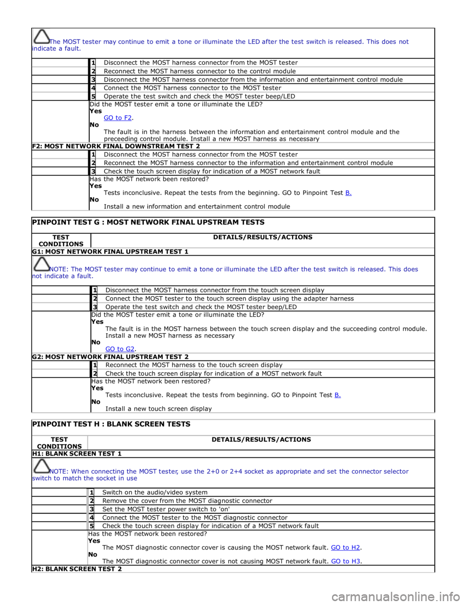
The MOST tester may continue to emit a tone or illuminate the LED after the test switch is released. This does not
indicate a fault. 1 Disconnect the MOST harness connector from the MOST tester 2 Reconnect the MOST harness connector to the control module 3 Disconnect the MOST harness connector from the information and entertainment control module 4 Connect the MOST harness connector to the MOST tester 5 Operate the test switch and check the MOST tester beep/LED Did the MOST tester emit a tone or illuminate the LED? Yes
GO to F2. No
The fault is in the harness between the information and entertainment control module and the preceeding control module. Install a new MOST harness as necessary F2: MOST NETWORK FINAL DOWNSTREAM TEST 2 1 Disconnect the MOST harness connector from the MOST tester 2 Reconnect the MOST harness connector to the information and entertainment control module 3 Check the touch screen display for indication of a MOST network fault Has the MOST network been restored? Yes
Tests inconclusive. Repeat the tests from the beginning. GO to Pinpoint Test B. No
Install a new information and entertainment control module
PINPOINT TEST G : MOST NETWORK FINAL UPSTREAM TESTS TEST
CONDITIONS DETAILS/RESULTS/ACTIONS G1: MOST NETWORK FINAL UPSTREAM TEST 1
NOTE: The MOST tester may continue to emit a tone or illuminate the LED after the test switch is released. This does
not indicate a fault. 1 Disconnect the MOST harness connector from the touch screen display 2 Connect the MOST tester to the touch screen display using the adapter harness 3 Operate the test switch and check the MOST tester beep/LED Did the MOST tester emit a tone or illuminate the LED? Yes
The fault is in the MOST harness between the touch screen display and the succeeding control module.
Install a new MOST harness as necessary
No
GO to G2. G2: MOST NETWORK FINAL UPSTREAM TEST 2 1 Reconnect the MOST harness to the touch screen display 2 Check the touch screen display for indication of a MOST network fault Has the MOST network been restored? Yes
Tests inconclusive. Repeat the tests from beginning. GO to Pinpoint Test B. No
Install a new touch screen display
PINPOINT TEST H : BLANK SCREEN TESTS TEST
CONDITIONS DETAILS/RESULTS/ACTIONS H1: BLANK SCREEN TEST 1
NOTE: When connecting the MOST tester, use the 2+0 or 2+4 socket as appropriate and set the connector selector
switch to match the socket in use 1 Switch on the audio/video system 2 Remove the cover from the MOST diagnostic connector 3 Set the MOST tester power switch to 'on' 4 Connect the MOST tester to the MOST diagnostic connector 5 Check the touch screen display for indication of a MOST network fault Has the MOST network been restored? Yes
The MOST diagnostic connector cover is causing the MOST network fault. GO to H2. No
The MOST diagnostic connector cover is not causing MOST network fault. GO to H3. H2: BLANK SCREEN TEST 2
Page 2149 of 3039
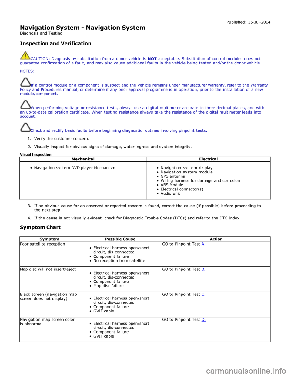
Navigation System - Navigation System
Diagnosis and Testing
Inspection and Verification Published: 15-Jul-2014
CAUTION: Diagnosis by substitution from a donor vehicle is NOT acceptable. Substitution of control modules does not
guarantee confirmation of a fault, and may also cause additional faults in the vehicle being tested and/or the donor vehicle.
NOTES:
If a control module or a component is suspect and the vehicle remains under manufacturer warranty, refer to the Warranty
Policy and Procedures manual, or determine if any prior approval programme is in operation, prior to the installation of a new
module/component.
When performing voltage or resistance tests, always use a digital multimeter accurate to three decimal places, and with
an up-to-date calibration certificate. When testing resistance always take the resistance of the digital multimeter leads into
account.
Check and rectify basic faults before beginning diagnostic routines involving pinpoint tests.
1. Verify the customer concern.
2. Visually inspect for obvious signs of damage, water ingress and system integrity.
Visual Inspection
Mechanical Electrical
Navigation system DVD player Mechanism
Navigation system display
Navigation system module
GPS antenna
Wiring harness for damage and corrosion
ABS Module
Electrical connector(s)
Audio unit
3. If an obvious cause for an observed or reported concern is found, correct the cause (if possible) before proceeding to
the next step.
4. If the cause is not visually evident, check for Diagnostic Trouble Codes (DTCs) and refer to the DTC Index.
Symptom Chart
Symptom Possible Cause Action Poor satellite reception
Electrical harness open/short
circuit, dis-connected
Component failure
No reception from satellite GO to Pinpoint Test A. Map disc will not insert/eject
Electrical harness open/short
circuit, dis-connected
Component failure
Map disc failure GO to Pinpoint Test B. Black screen (navigation map
screen does not display)
Electrical harness open/short
circuit, dis-connected
Component failure
GVIF cable GO to Pinpoint Test C. Navigation map screen color
is abnormal
Electrical harness open/short
circuit, dis-connected
Component failure
GVIF cable GO to Pinpoint Test D.