2010 INFINITI QX56 upper
[x] Cancel search: upperPage 1957 of 4210
EM-106
< DISASSEMBLY AND ASSEMBLY >
HOW TO SELECT PISTON AND BEARING
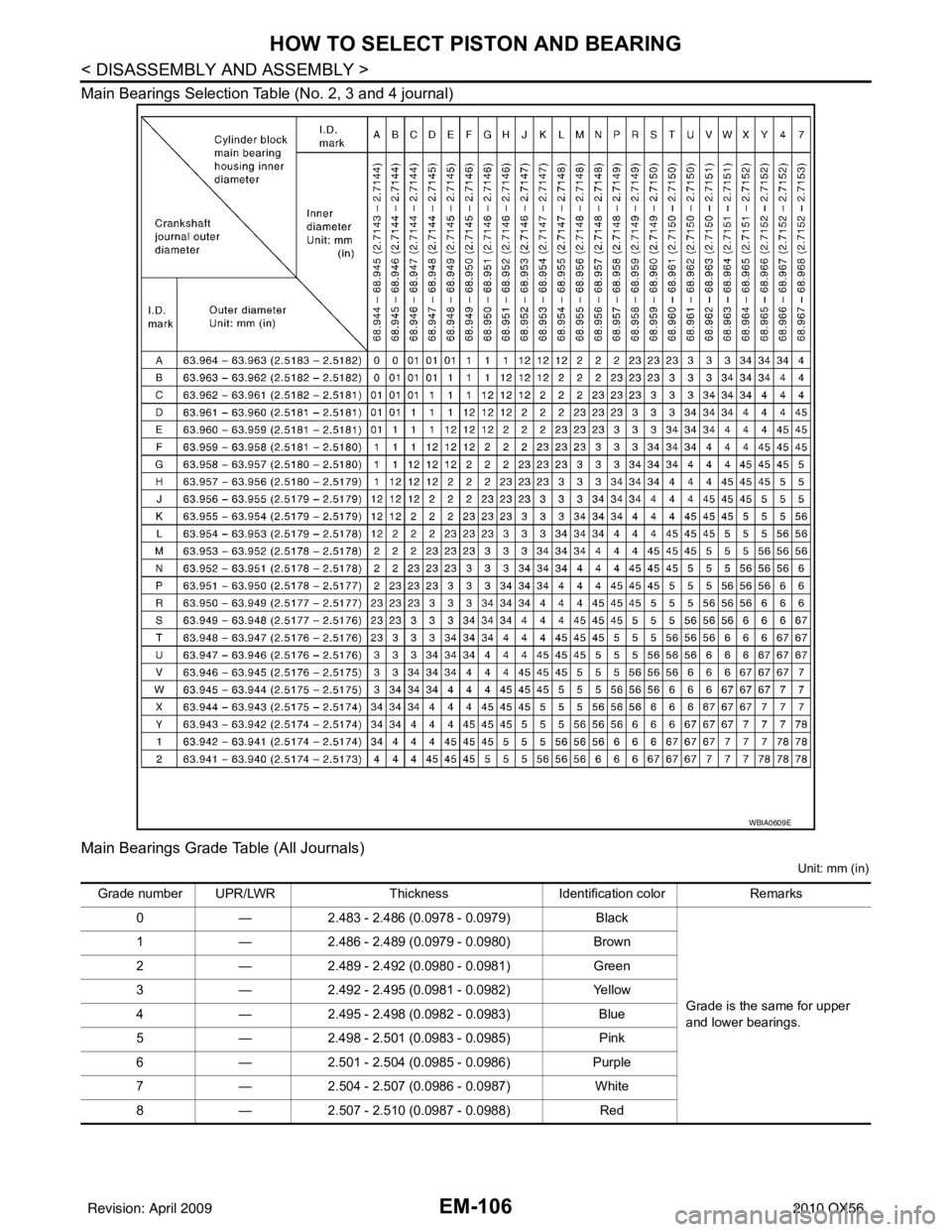
Main Bearings Selection Table (No. 2, 3 and 4 journal)
Main Bearings Grade Table (All Journals)
Unit: mm (in)
WBIA0609E
Grade number UPR/LWRThickness Identification color Remarks
0 —2.483 - 2.486 (0.0978 - 0.0979) Black
Grade is the same for upper
and lower bearings.
1
—2.486 - 2.489 (0.0979 - 0.0980) Brown
2 —2.489 - 2.492 (0.0980 - 0.0981) Green
3 —2.492 - 2.495 (0.0981 - 0.0982) Yellow
4 —2.495 - 2.498 (0.0982 - 0.0983) Blue
5 —2.498 - 2.501 (0.0983 - 0.0985) Pink
6 —2.501 - 2.504 (0.0985 - 0.0986) Purple
7 —2.504 - 2.507 (0.0986 - 0.0987) White
8 —2.507 - 2.510 (0.0987 - 0.0988) Red
Revision: April 20092010 QX56
Page 1958 of 4210
HOW TO SELECT PISTON AND BEARINGEM-107
< DISASSEMBLY AND ASSEMBLY >
C
DE
F
G H
I
J
K L
M A
EM
NP
O
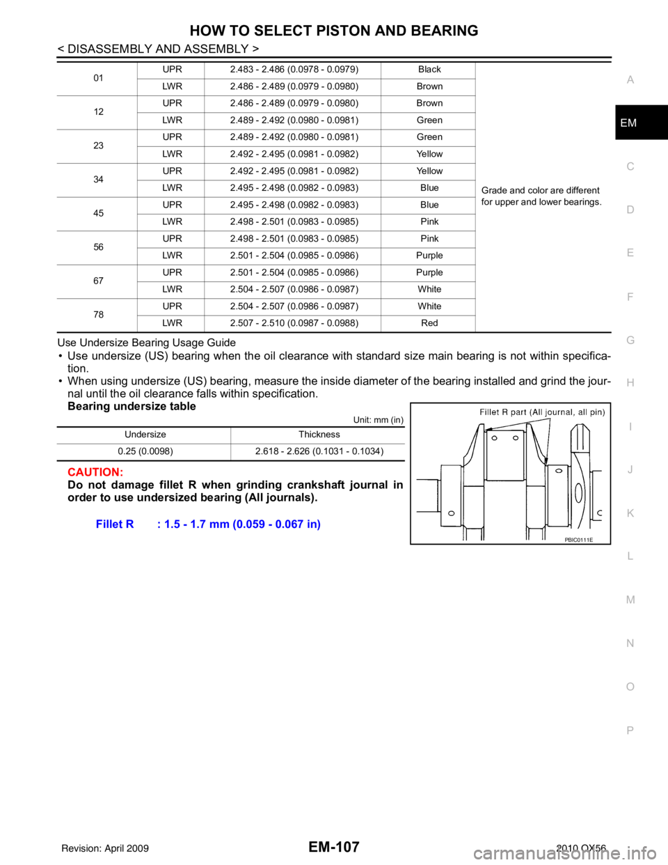
Use Undersize Bearing Usage Guide
• Use undersize (US) bearing when the oil clearance with
standard size main bearing is not within specifica-
tion.
• When using undersize (US) bearing, measure the inside di ameter of the bearing installed and grind the jour-
nal until the oil clearance falls within specification.
Bearing undersize table
Unit: mm (in)
CAUTION:
Do not damage fillet R when grinding crankshaft journal in
order to use undersized bearing (All journals).
01 UPR
2.483 - 2.486 (0.0978 - 0.0979) Black
Grade and color are different
for upper and lower bearings.
LWR
2.486 - 2.489 (0.0979 - 0.0980) Brown
12 UPR
2.486 - 2.489 (0.0979 - 0.0980) Brown
LWR 2.489 - 2.492 (0.0980 - 0.0981) Green
23 UPR
2.489 - 2.492 (0.0980 - 0.0981) Green
LWR 2.492 - 2.495 (0.0981 - 0.0982) Yellow
34 UPR
2.492 - 2.495 (0.0981 - 0.0982) Yellow
LWR 2.495 - 2.498 (0.0982 - 0.0983) Blue
45 UPR
2.495 - 2.498 (0.0982 - 0.0983) Blue
LWR 2.498 - 2.501 (0.0983 - 0.0985) Pink
56 UPR
2.498 - 2.501 (0.0983 - 0.0985) Pink
LWR 2.501 - 2.504 (0.0985 - 0.0986) Purple
67 UPR
2.501 - 2.504 (0.0985 - 0.0986) Purple
LWR 2.504 - 2.507 (0.0986 - 0.0987) White
78 UPR
2.504 - 2.507 (0.0986 - 0.0987) White
LWR 2.507 - 2.510 (0.0987 - 0.0988) Red
UndersizeThickness
0.25 (0.0098) 2.618 - 2.626 (0.1031 - 0.1034)
Fillet R : 1.5 - 1.7 mm (0.059 - 0.067 in)
PBIC0111E
Revision: April 20092010 QX56
Page 1968 of 4210
SERVICE DATA AND SPECIFICATIONS (SDS)EM-117
< SERVICE DATA AND SPECIFICATIONS (SDS)
C
DE
F
G H
I
J
K L
M A
EM
NP
O
*: Always check with the Parts Department for the latest parts information
Undersize
Unit: mm (in)
Main Bearing Oil Clearance
Unit: mm (in)
Connecting Rod Bearing
*: Always check with the Parts Department for the latest parts information
Undersize
0
—2.483 - 2.486 (0.0978 - 0.0979) Black
Grade is the same for upper
and lower bearings
1
—2.486 - 2.489 (0.0979 - 0.0980) Brown
2 —2.489 - 2.492 (0.0980 - 0.0981) Green
3 —2.492 - 2.495 (0.0981 - 0.0982) Yellow
4 —2.495 - 2.498 (0.0982 - 0.0983) Blue
5 —2.498 - 2.501 (0.0983 - 0.0985) Pink
6 —2.501 - 2.504 (0.0985 - 0.0986) Purple
7 —2.504 - 2.507 (0.0986 - 0.0987) White
8 —2.507 - 2.510 (0.0987 - 0.0988) Red
01 UPR
2.483 - 2.486 (0.0978 - 0.0979) Black
Grade is different for upper and
lower bearings.
LWR
2.486 - 2.489 (0.0979 - 0.0980) Brown
12 UPR
2.486 - 2.489 (0.0979 - 0.0980) Brown
LWR 2.489 - 2.492 (0.0980 - 0.0981) Green
23 UPR
2.489 - 2.492 (0.0980 - 0.0981) Green
LWR 2.492 - 2.495 (0.0981 - 0.0982) Yellow
34 UPR
2.492 - 2.495 (0.0981 - 0.0982) Yellow
LWR 2.495 - 2.498 (0.0982 - 0.0983) Blue
45 UPR
2.495 - 2.498 (0.0982 - 0.0983) Blue
LWR 2.498 - 2.501 (0.0983 - 0.0985) Pink
56 UPR
2.498 - 2.501 (0.0983 - 0.0985) Pink
LWR 2.501 - 2.504 (0.0985 - 0.0986) Purple
67 UPR
2.501 - 2.504 (0.0985 - 0.0986) Purple
LWR 2.504 - 2.507 (0.0986 - 0.0987) White
78 UPR
2.504 - 2.507 (0.0986 - 0.0987) White
LWR 2.507 - 2.510 (0.0987 - 0.0988) Red
UndersizeThickness Main journal diameter
0.25 (0.0098) 2.618 - 2.626 (0.1031 - 0.1034) Grind so that bearing clearance is the specified value.
Items StandardLimit
Main bearing oil clearance No.1 and 5
0.001 - 0.011 (0.00004 - 0.0004) 0.021 (0.0008)
No.2, 3 and 4 0.007 - 0.017 (0.0003 - 0.0007) 0.027 (0.0011)
Grade number*Thickness “T” mm (in) Identification color (mark)
0 1.500 - 1.503 (0.0591 - 0.0592) Black
1 1.503 - 1.506 (0.0592 - 0.0593) Brown
2 1.506 - 1.509 (0.0593 - 0.0594) Green
3 1.509 - 1.512 (0.0594 - 0.0595) Yellow
Revision: April 20092010 QX56
Page 2133 of 4210
STOP LAMPEXL-157
< REMOVAL AND INSTALLATION >
C
DE
F
G H
I
J
K
M A
B
EXL
N
O P
STOP LAMP
Bulb ReplacementINFOID:0000000005146708
HIGH-MOUNTED STOP LAMP
NOTE:
High-mounted stop lamp bulbs are not serviceable.
STOP LAMP
Refer to EXL-157, "Removal and Installation".
Removal and InstallationINFOID:0000000005146709
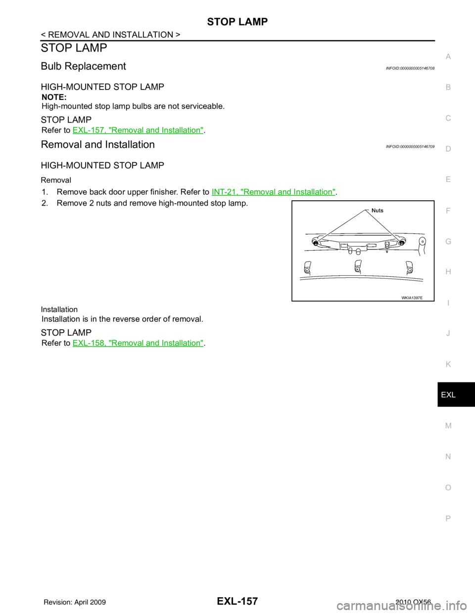
HIGH-MOUNTED STOP LAMP
Removal
1. Remove back door upper finisher. Refer to INT-21, "Removal and Installation".
2. Remove 2 nuts and remove high-mounted stop lamp.
Installation
Installation is in the reverse order of removal.
STOP LAMP
Refer to EXL-158, "Removal and Installation".
WKIA1397E
Revision: April 20092010 QX56
Page 2148 of 4210
FRONT BUMPEREXT-13
< SERVICE INFORMATION >
C
DE
F
G H
I
J
L
M A
B
EXT
N
O P
FRONT BUMPER
Removal and InstallationINFOID:0000000005147318
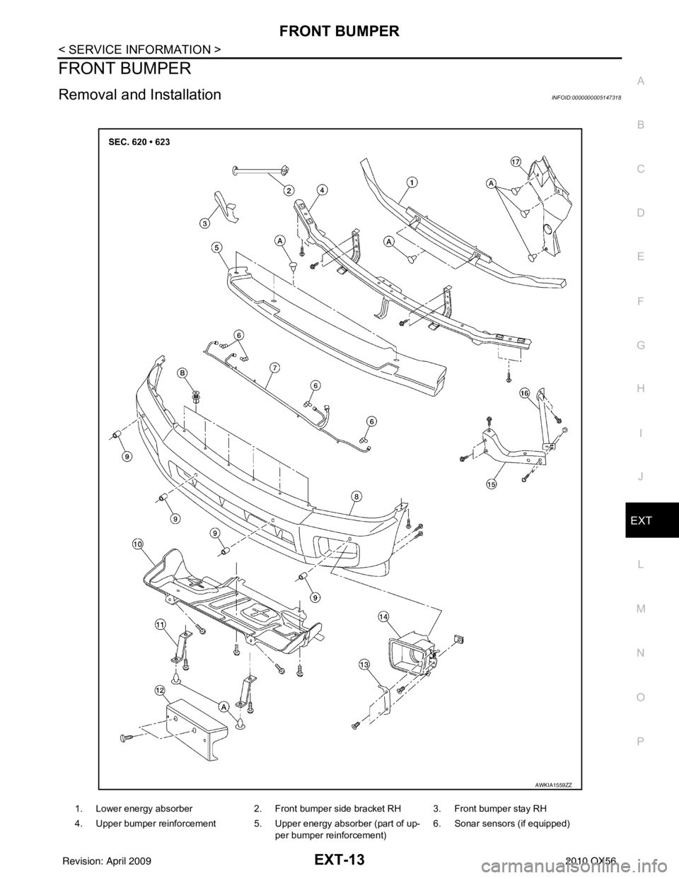
1. Lower energy absorber 2. Front bumper side bracket RH 3. Front bumper stay RH
4. Upper bumper reinforcement 5. Upper energy absorber (part of up- per bumper reinforcement) 6. Sonar sensors (if equipped)
AWKIA1559ZZ
Revision: April 20092010 QX56
Page 2149 of 4210
EXT-14
< SERVICE INFORMATION >
FRONT BUMPER
REMOVAL
1. Remove the side screws from the front fascia assembly.
2. Remove the screws from the front of fender protector. Refer to EXT-23
.
3. Remove the fog turn/fog lamp finisher and the fog turn/fog lamp. • Disconnect the harnesses.
4. Disconnect the sonar sensor, if equipped harness connector under the front fascia assembly.
5. Remove the fasteners, release the clips and remove the front fascia assembly.
6. Remove the plastic clips and remove the upper energy absorber.
7. Remove the upper bumper reinforcement.
8. Remove the plastic clips and remove the lower energy absorber.
9. Remove the front bumper stays and the front bumper side brackets, LH and RH.
10. Disconnect the sonar sensors, if equipped from the sonar sensor retainers, if equipped.
11. Remove the sonar sensors, if equipped and harness from the front fascia assembly. • Disconnect the sonar sensors, if equipped from the harness.
• Remove the sonar sensor retainers, if equipped from the front fascia assembly.
INSTALLATION
Installation is in the reverse order of removal.
7. Sonar sensor harness (if equipped) 8. Front fascia assembly 9. Sonar sensor retainers (if equipped)
10. Engine under cover 11. Front fascia bracket12. License plate bracket
13. Fog turn/fog lamp finisher LH/RH 14. Fog turn/fog lamp 15. Front bumper stay LH
16. Front bumper side bracket LH 17. Headlamp finisher (RH shown) A. Clip C103
B. Clip CS101
Revision: April 20092010 QX56
Page 2175 of 4210
DRIVE SHAFTFAX-9
< REMOVAL AND INSTALLATION >
CEF
G H
I
J
K L
M A
B
FA X
N
O P
DRIVE SHAFT
Removal and InstallationINFOID:0000000005148945
REMOVAL
1. Remove wheel and tire using power tool.
2. Remove engine under cover using power tool.
3. Remove wheel sensor harness from mount on knuckle and reposition aside. Refer to BRC-114, "
Removal
and Installation".
CAUTION:
Do not pull on wheel sensor harness.
4. Without disassembling the hydraulic lines, remove brake caliper using power tool. Reposition it aside with wire. Refer to BR-31, "
Removal and Installation of Brake Caliper and Rotor" .
NOTE:
Avoid depressing brake pedal while brake caliper is removed.
5. Remove coil spring and shock absorber assembly using power tool. Refer to FSU-14, "
Removal and
Installation" .
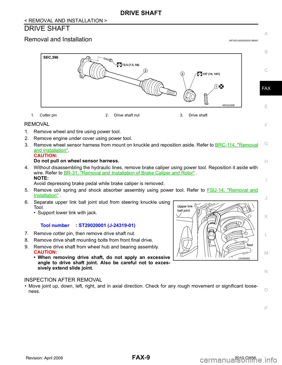
6. Separate upper link ball joint stud from steering knuckle using Tool.
• Support lower link with jack.
7. Remove cotter pin, then remove drive shaft nut.
8. Remove drive shaft mounting bolts from front final drive.
9. Remove drive shaft from wheel hub and bearing assembly. CAUTION:
• When removing drive shaf t, do not apply an excessive
angle to drive shaft joint. Also be careful not to exces-
sively extend slide joint.
INSPECTION AFTER REMOVAL
• Move joint up, down, left, right, and in axial directi on. Check for any rough movement or significant loose-
ness.
1. Cotter pin 2. Drive shaft nut3. Drive shaft
WDIA0329E
Tool number : ST29020001 (J-24319-01)
LEIA0095E
Revision: April 20092010 QX56
Page 2200 of 4210
FSU-1
SUSPENSION
C
DF
G H
I
J
K L
M
SECTION FSU
A
B
FSU
N
O PCONTENTS
FRONT SUSPENSION
PRECAUTION ....... ........................................2
PRECAUTIONS .............................................. .....2
Precaution for Supplemental Restraint System
(SRS) "AIR BAG" and "SEAT BELT PRE-TEN-
SIONER" ............................................................. ......
2
Precaution Necessary for Steering Wheel Rota-
tion After Battery Disconnect ............................... ......
2
Precaution .................................................................3
PREPARATION ............................................4
PREPARATION .............................................. .....4
Special Service Tool ........................................... ......4
Commercial Service Tool ..........................................4
SYMPTOM DIAGNOSIS ...............................5
NOISE, VIBRATION AND HARSHNESS
(NVH) TROUBLESHOOTING ........................ .....
5
NVH Troubleshooting Chart ................................ ......5
ON-VEHICLE MAINTENANCE .....................6
ON-VEHICLE SERVICE ................................. .....6
Front Suspension Parts ....................................... ......6
Front Wheel Alignment ..............................................6
UPPER BALL JOINT AND LOWER BALL
JOINT .................................................................
10
Inspection ............................................................ ....10
KNUCKLE ...................................................... ....12
On-Vehicle Inspection and Service ..................... ....12
ON-VEHICLE REPAIR .................................13
FRONT SUSPENSION ASSEMBLY .............. ....13
Component .......................................................... ....13
REMOVAL AND INSTALLATION ...............14
COIL SPRING AND SHOCK ABSORBER .......14
Removal and Installation ..................................... ....14
Disposal ...................................................................14
STABILIZER BAR .............................................15
Removal and Installation .........................................15
UPPER LINK .....................................................16
Removal and Installation ..................................... ....16
LOWER LINK ....................................................17
Removal and Installation .........................................17
UPPER BALL JOINT AND LOWER BALL
JOINT ................................................................
18
Removal and Installation .........................................18
KNUCKLE .........................................................19
Removal and Installation ..................................... ....19
DISASSEMBLY AND ASSEMBLY ..............21
COIL SPRING AND SHOCK ABSORBER .......21
Disassembly and Assembly ................................. ....21
SERVICE DATA AND SPECIFICATIONS
(SDS) ............... .......................................... ...
23
SERVICE DATA AND SPECIFICATIONS
(SDS) .................................................................
23
General Specification .......................................... ....23
Spring Free Height ..................................................23
Wheel Alignment (Unladen*1) ..................................23
Ball Joint .............................................................. ....24
Wheelarch Height (Unladen*1) ................................24
Revision: April 20092010 QX56