Page 2203 of 4210
FSU-4
< PREPARATION >
PREPARATION
PREPARATION
PREPARATION
Special Service ToolINFOID:0000000005148105
The actual shapes of Kent-Moore tools may differ from those of special service tools illustrated here.
Commercial Service ToolINFOID:0000000005148106
Tool number
(Kent-Moore No.)
Tool name Description
ST29020001
(J-24319-01)
Pitman arm puller Removing upper link ball joint from knuckle
spindle
a: 34 mm (1.34 in)
b: 6.5 mm (0.256 in)
c: 61.5 mm (2.421 in)
HT72520000
(J-25730-A)
Ball joint remover Removing tie-rod outer end
NT694
NT146
Tool name
Description
Attachment wheel alignment Measure wheel alignment
a: Screw M24 x 1.5 pitch
b: 35 mm (1.38 in) dia.
c: 65 mm (2.56 in) dia.
d: 56 mm (2.20 in)
e: 12 mm (0.47 in)
Spring compressor Removing and installing coil spring
Power tool Loosening bolts and nuts
NT148
NT717
PBIC0190E
Revision: April 20092010 QX56
Page 2209 of 4210

FSU-10
< ON-VEHICLE MAINTENANCE >
UPPER BALL JOINT AND LOWER BALL JOINT
UPPER BALL JOINT AND LOWER BALL JOINT
InspectionINFOID:0000000005148110
• Check the ball joint for excessive play. Replace the upper or lower link assembly if any of the followingexists:
- Ball joint stud is worn.
- Ball joint is hard to swing.
- Ball joint play in axial directions or end play is excessive.
Swinging Force
NOTE:
Before checking the axial forces and end play, turn the lower ball joint at least 10 revolutions so that the ball
joint is properly broken in.
1. Measure the ball joint swinging force using a suitable tool.
• Measure at the cotter pin hole for upper ball joint as shown.
• Measure at the groove for lower ball joint as shown.
2. Verify the ball joint swinging force is within specification.
Turning Force
Check the turning torque using a suitable tool.
NOTE:
Before checking the axial forces and end play, turn the lower ball
joint at least 10 revolutions so that the ball joint is properly broken in.
Vertical End Play
Check dust cover for damage. Replace it and the cover clamp if necessary.
NOTE:
WEIA0076E
Swinging force (A)
Upper ball joint : 8.1 - 103.2 N (0.8 - 10.5 kg-f, 1.8 - 23.2 lb-f)
Lower ball joint : 11.4 - 145.5 N (1.1 - 14.8 kg-f, 2.5 - 32.7 lb-f)
SFA858A
Turning torque (B) : 0.5 - 6.4 N·m (0.05 - 0.65 kg-m, 4 - 57 in-lb)
SFA858A
Revision: April 20092010 QX56
Page 2210 of 4210
UPPER BALL JOINT AND LOWER BALL JOINTFSU-11
< ON-VEHICLE MAINTENANCE >
C
DF
G H
I
J
K L
M A
B
FSU
N
O P
Before checking the axial forces and end play, turn the lower ball
joint at least 10 revolutions so that the ball joint is properly broken in. Vertical end play (C) : 0 mm (0 in)
SFA858A
Revision: April 20092010 QX56
Page 2212 of 4210
FRONT SUSPENSION ASSEMBLYFSU-13
< ON-VEHICLE REPAIR >
C
DF
G H
I
J
K L
M A
B
FSU
N
O P
ON-VEHICLE REPAIR
FRONT SUSPENSION ASSEMBLY
ComponentINFOID:0000000005148112
1. Dust cover 2. Shock absorber 3. Upper link
4. Steering knuckle 5. Cotter pin 6. Bolt
7. Jounce bumper 8. Washer 9. Lower link
10. Stabilizer bar 11. Stabilizer bar bushing 12. Stabilizer bar mounting bracket
13. Connecting rod 14. Coil spring 15. Upper seat
16. Upper spring seat 17. Shock absorber bushing 18. Shock absorber mounting insulator
19. Spacer 20. Washer Front
AWEIA0142GB
Revision: April 20092010 QX56
Page 2213 of 4210

FSU-14
< REMOVAL AND INSTALLATION >
COIL SPRING AND SHOCK ABSORBER
REMOVAL AND INSTALLATION
COIL SPRING AND SHOCK ABSORBER
Removal and InstallationINFOID:0000000005148113
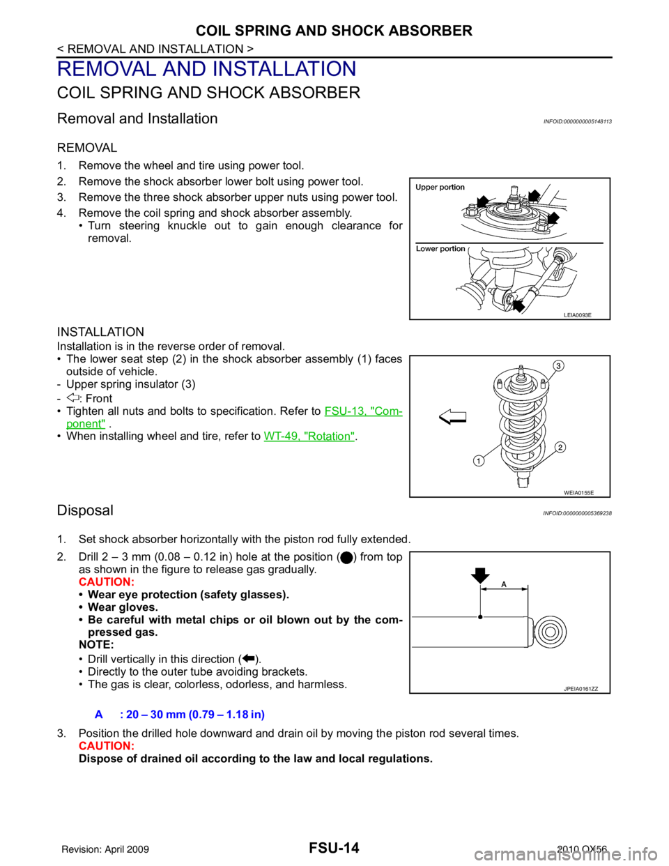
REMOVAL
1. Remove the wheel and tire using power tool.
2. Remove the shock absorber lower bolt using power tool.
3. Remove the three shock absorber upper nuts using power tool.
4. Remove the coil spring and shock absorber assembly.• Turn steering knuckle out to gain enough clearance forremoval.
INSTALLATION
Installation is in the reverse order of removal.
• The lower seat step (2) in the shock absorber assembly (1) faces
outside of vehicle.
- Upper spring insulator (3)
- : Front
• Tighten all nuts and bolts to specification. Refer to FSU-13, "
Com-
ponent" .
• When installing wheel and tire, refer to WT-49, "
Rotation".
DisposalINFOID:0000000005369238
1. Set shock absorber horizontally with the piston rod fully extended.
2. Drill 2 – 3 mm (0.08 – 0.12 in) hole at the position ( ) from top
as shown in the figure to release gas gradually.
CAUTION:
• Wear eye protection (safety glasses).
• Wear gloves.
• Be careful with metal chips or oil blown out by the com-pressed gas.
NOTE:
• Drill vertically in this direction ( ).
• Directly to the outer tube avoiding brackets.
• The gas is clear, colorless, odorless, and harmless.
3. Position the drilled hole downward and drain oil by moving the piston rod several times. CAUTION:
Dispose of drained oil according to the law and local regulations.
LEIA0093E
WEIA0155E
A : 20 – 30 mm (0.79 – 1.18 in)
JPEIA0161ZZ
Revision: April 20092010 QX56
Page 2215 of 4210

FSU-16
< REMOVAL AND INSTALLATION >
UPPER LINK
UPPER LINK
Removal and InstallationINFOID:0000000005148115
REMOVAL
1. Remove the wheel and tire using power tool.
2. Remove the fender protector to access upper link. Refer to EXT-23, "
Removal and Installation" .
3. Remove cotter pin and nut from upper link ball joint and discard the cotter pin.
4. Separate upper link ball joint stud from steering knuckle using Tool.
• Support lower link with jack.
5. Remove upper link bolts and nuts, then remove upper link.
INSPECTION AFTER REMOVAL
Upper Link
Check for deformation and cracks. Replace if necessary.
Upper Link Ball Joint
Check for distortion and damage. Replace if necessary.
INSTALLATION
Installation is in the reverse order of removal.
• Tighten all nuts and bolts to specification. Refer to FSU-13, "
Component".
CAUTION:
Use a new cotter pin for installation of upper link ball joint nut.
• When installing wheel and tire, refer to WT-49, "
Rotation".
• After installation, check that the front wheel alignment is within specification. Refer to FSU-6, "
Front Wheel
Alignment" .
Tool number : ST29020001 (J-24319-01)
LEIA0095E
LEIA0096E
Revision: April 20092010 QX56
Page 2217 of 4210
FSU-18
< REMOVAL AND INSTALLATION >
UPPER BALL JOINT AND LOWER BALL JOINT
UPPER BALL JOINT AND LOWER BALL JOINT
Removal and InstallationINFOID:0000000005148117
The ball joints are part of the upper and lower links. Refer to FSU-16, "Removal and Installation" (upper link),
FSU-17, "
Removal and Installation" (lower link).
Revision: April 20092010 QX56
Page 2218 of 4210

KNUCKLEFSU-19
< REMOVAL AND INSTALLATION >
C
DF
G H
I
J
K L
M A
B
FSU
N
O P
KNUCKLE
Removal and InstallationINFOID:0000000005148118
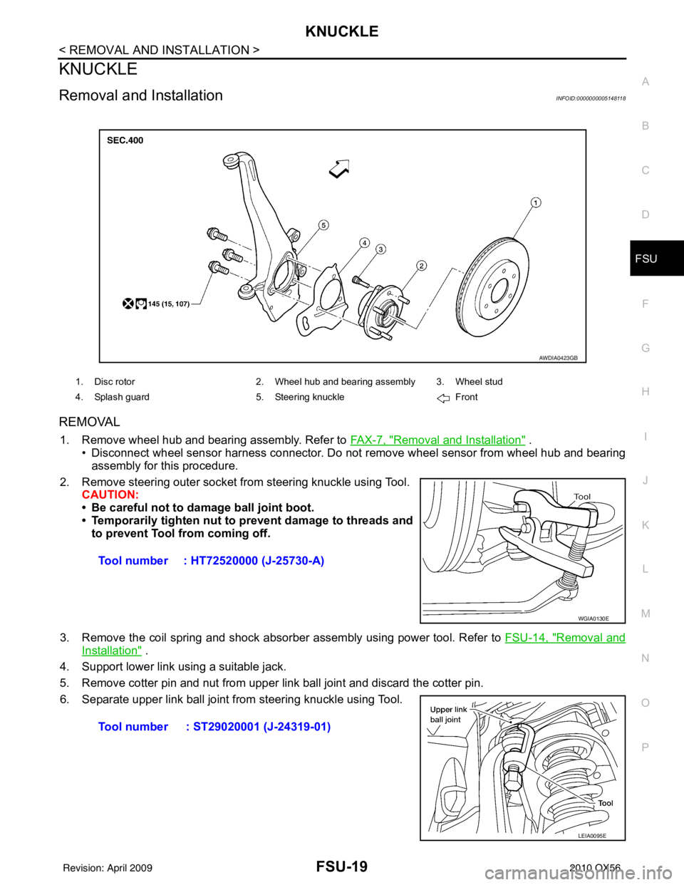
REMOVAL
1. Remove wheel hub and bearing assembly. Refer to FAX-7, "Removal and Installation" .
• Disconnect wheel sensor harness connector. Do not remove wheel sensor from wheel hub and bearing
assembly for this procedure.
2. Remove steering outer socket from steering knuckle using Tool. CAUTION:
• Be careful not to damage ball joint boot.
• Temporarily tighten nut to prevent damage to threads andto prevent Tool from coming off.
3. Remove the coil spring and shock absorber assembly using power tool. Refer to FSU-14, "
Removal and
Installation" .
4. Support lower link using a suitable jack.
5. Remove cotter pin and nut from upper link ball joint and discard the cotter pin.
6. Separate upper link ball joint from steering knuckle using Tool.
1. Disc rotor 2. Wheel hub and bearing assembly 3. Wheel stud
4. Splash guard 5. Steering knuckle Front
AWDIA0423GB
Tool number : HT72520000 (J-25730-A)
WGIA0130E
Tool number : ST29020001 (J-24319-01)
LEIA0095E
Revision: April 20092010 QX56