2010 INFINITI QX56 upper
[x] Cancel search: upperPage 2566 of 4210
INT-14
< ON-VEHICLE REPAIR >
BODY SIDE TRIM
BODY SIDE TRIM
Removal and InstallationINFOID:0000000005147350
CAUTION:
• Wrap the tip of flat-bladed screwdriver with a cloth when removing metal clips from finishers.
• When removing or installing body side welts, do not allow butyl seal to come in contact with pillar
finisher.
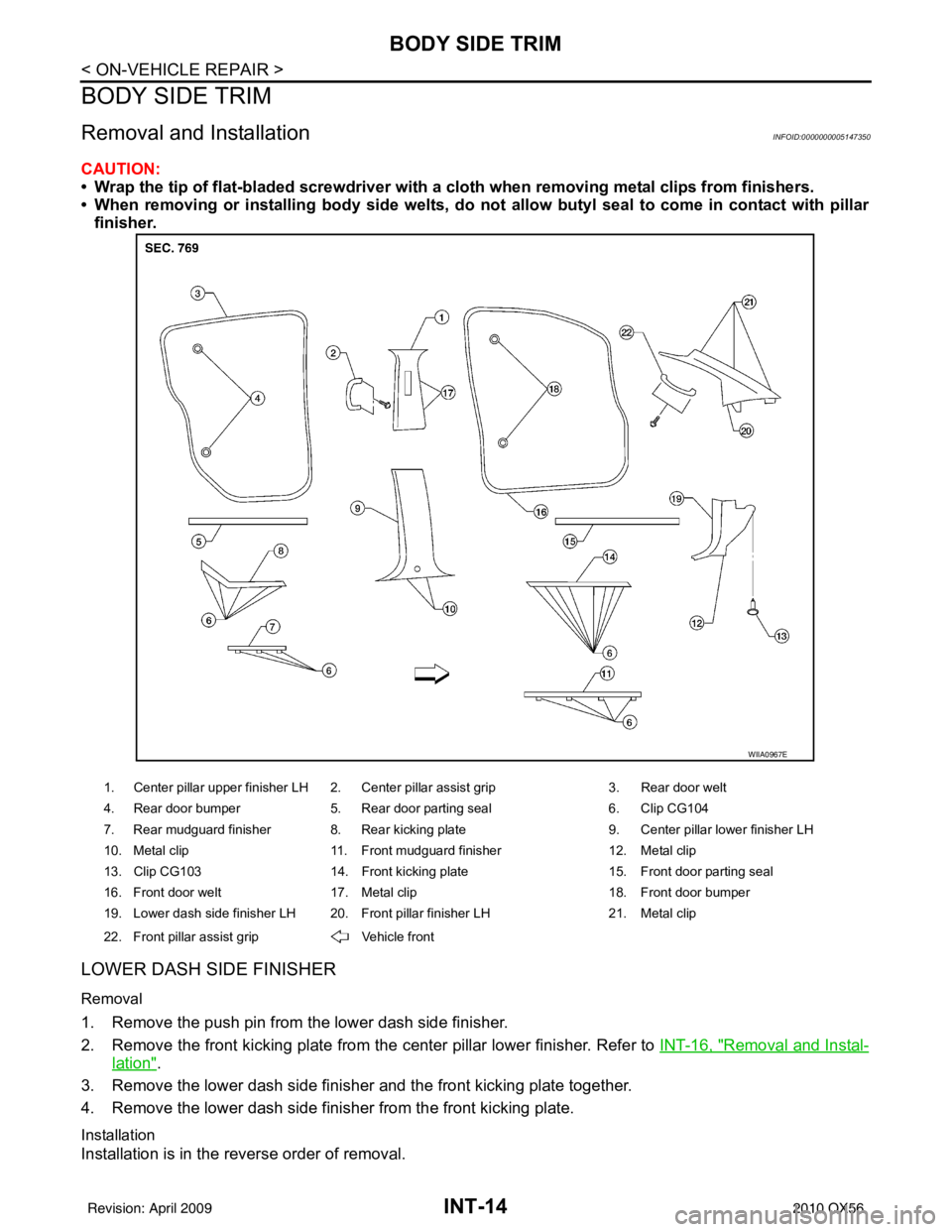
LOWER DASH SIDE FINISHER
Removal
1. Remove the push pin from the lower dash side finisher.
2. Remove the front kicking plate from the center pillar lower finisher. Refer to INT-16, "
Removal and Instal-
lation".
3. Remove the lower dash side finisher and the front kicking plate together.
4. Remove the lower dash side finisher from the front kicking plate.
Installation
Installation is in the reverse order of removal.
1. Center pillar upper finisher LH 2. Center pillar assist grip 3. Rear door welt
4. Rear door bumper 5. Rear door parting seal 6. Clip CG104
7. Rear mudguard finisher 8. Rear kicking plate 9. Center pillar lower finisher LH
10. Metal clip 11. Front mudguard finisher 12. Metal clip
13. Clip CG103 14. Front kicking plate 15. Front door parting seal
16. Front door welt 17. Metal clip 18. Front door bumper
19. Lower dash side finisher LH 20. Front pillar finisher LH 21. Metal clip
22. Front pillar assist grip Vehicle front
WIIA0967E
Revision: April 20092010 QX56
Page 2567 of 4210
BODY SIDE TRIMINT-15
< ON-VEHICLE REPAIR >
C
DE
F
G H
I
K L
M A
B
INT
N
O P
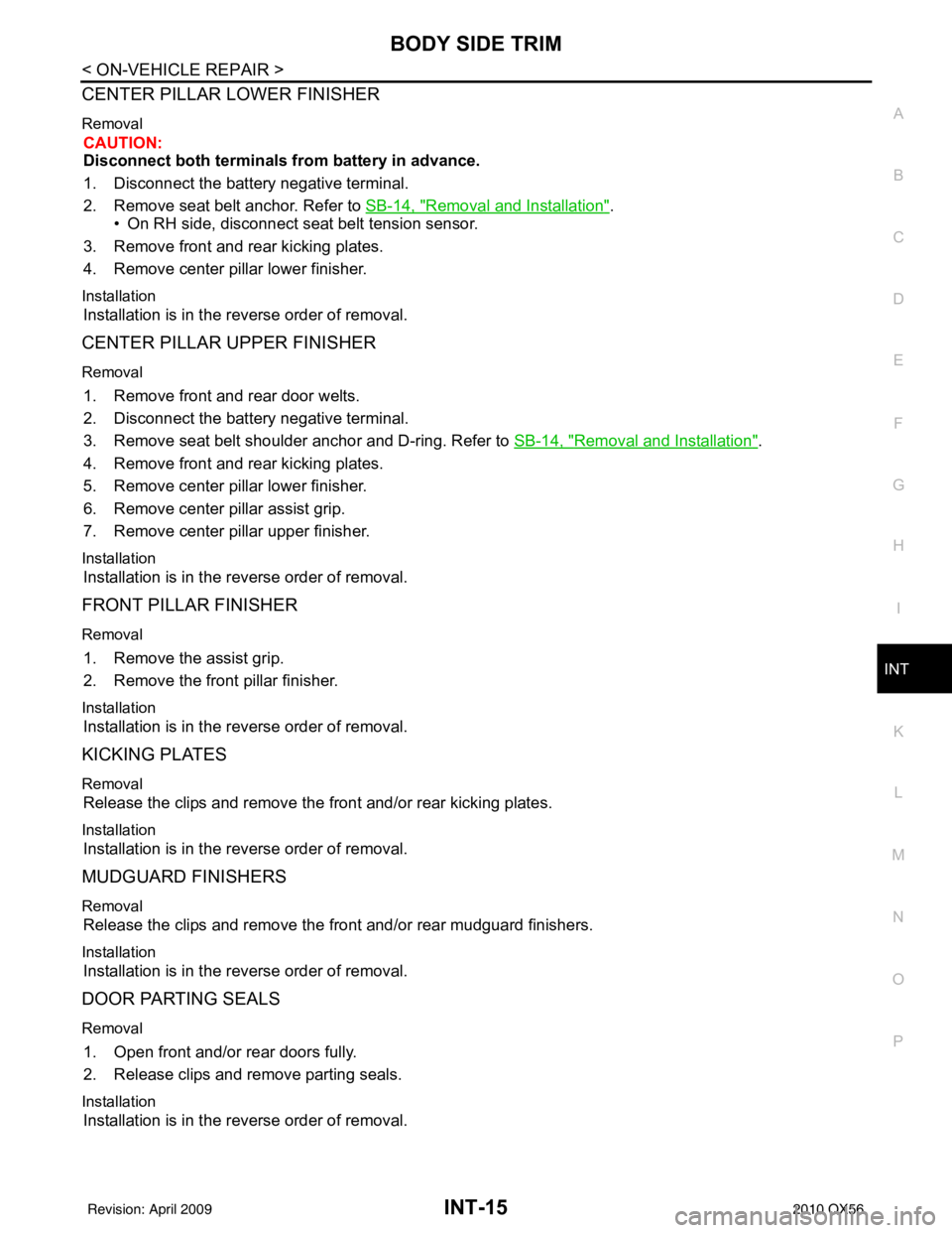
CENTER PILLAR LOWER FINISHER
Removal
CAUTION:
Disconnect both terminals from battery in advance.
1. Disconnect the battery negative terminal.
2. Remove seat belt anchor. Refer to SB-14, "
Removal and Installation".
• On RH side, disconnect seat belt tension sensor.
3. Remove front and rear kicking plates.
4. Remove center pillar lower finisher.
Installation
Installation is in the reverse order of removal.
CENTER PILLAR UPPER FINISHER
Removal
1. Remove front and rear door welts.
2. Disconnect the battery negative terminal.
3. Remove seat belt shoulder anchor and D-ring. Refer to SB-14, "
Removal and Installation".
4. Remove front and rear kicking plates.
5. Remove center pillar lower finisher.
6. Remove center pillar assist grip.
7. Remove center pillar upper finisher.
Installation
Installation is in the reverse order of removal.
FRONT PILLAR FINISHER
Removal
1. Remove the assist grip.
2. Remove the front pillar finisher.
Installation
Installation is in the reverse order of removal.
KICKING PLATES
Removal
Release the clips and remove the front and/or rear kicking plates.
Installation
Installation is in the reverse order of removal.
MUDGUARD FINISHERS
Removal
Release the clips and remove the front and/or rear mudguard finishers.
Installation
Installation is in the reverse order of removal.
DOOR PARTING SEALS
Removal
1. Open front and/or rear doors fully.
2. Release clips and remove parting seals.
Installation
Installation is in the reverse order of removal.
Revision: April 20092010 QX56
Page 2571 of 4210
LUGGAGE FLOOR TRIMINT-19
< ON-VEHICLE REPAIR >
C
DE
F
G H
I
K L
M A
B
INT
N
O P
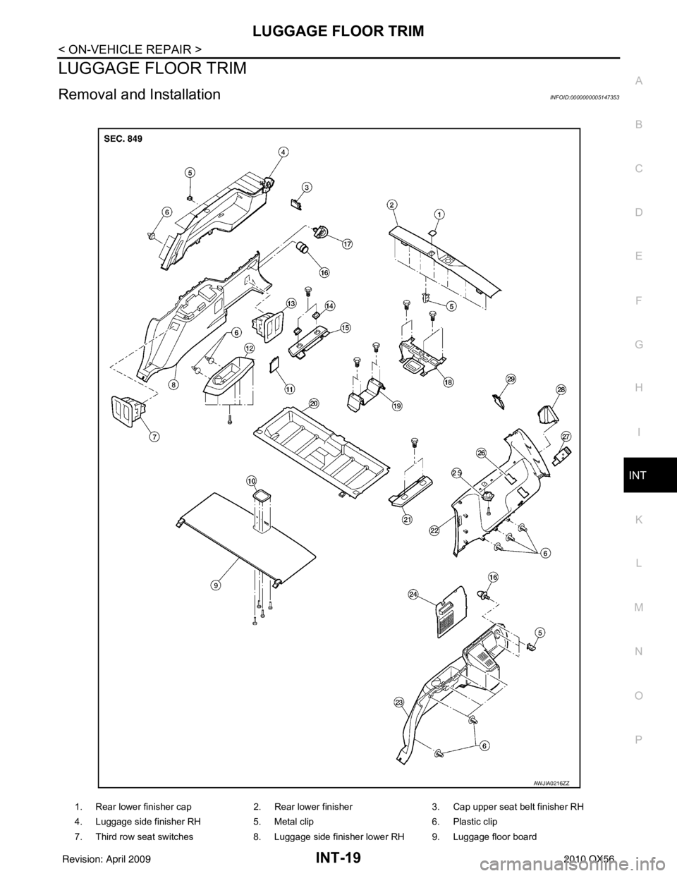
LUGGAGE FLOOR TRIM
Removal and InstallationINFOID:0000000005147353
1. Rear lower finisher cap 2. Rear lower finisher3. Cap upper seat belt finisher RH
4. Luggage side finisher RH 5. Metal clip6. Plastic clip
7. Third row seat switches 8. Luggage side finisher lower RH 9. Luggage floor board
AWJIA0216ZZ
Revision: April 20092010 QX56
Page 2572 of 4210
INT-20
< ON-VEHICLE REPAIR >
LUGGAGE FLOOR TRIM
REMOVAL
1. Remove the 2nd and 3rd row seat belts. Refer to SB-7, "Removal and Installation of Second Row Seat
Belt" and SB-8, "Removal and Installation of Third Row Seat Belt".
2. Remove the third row seat belt buckles.
3. Remove the third row seat assembly. Refer to SE-77, "
Exploded View".
4. Remove the back door weatherstrip. Refer to INT-21
.
5. Remove the rear luggage room lamp. Refer to INT-17
.
• Disconnect the harness from lamp.
6. Remove the rear upper finisher. Refer to INT-17
.
7. Remove the rear door kicking plates. Refer to INT-14
.
8. Remove the rear lower finisher.
9. Disconnect the door open/close link. Refer to INT-21, "
Removal and Installation".
10. Remove the cargo net hooks.
11. Remove the luggage side lower finishers LH/RH. • Disconnect the power point and the third row seat harness connectors RH side, if equipped.
12. Remove the coat hooks.
13. Remove the luggage side upper finishers LH/RH. • Disconnect the harness to door open/close switch, LH side.
14. Remove the tie down hooks LH/RH.
15. Remove the floor side finishers LH/RH.
16. Remove the luggage floor board.
17. Remove the storage box.
18. Remove the front luggage floor bracket.
19. Remove the rear luggage box bracket.
INSTALLATION
Installation is in the reverse order of removal.
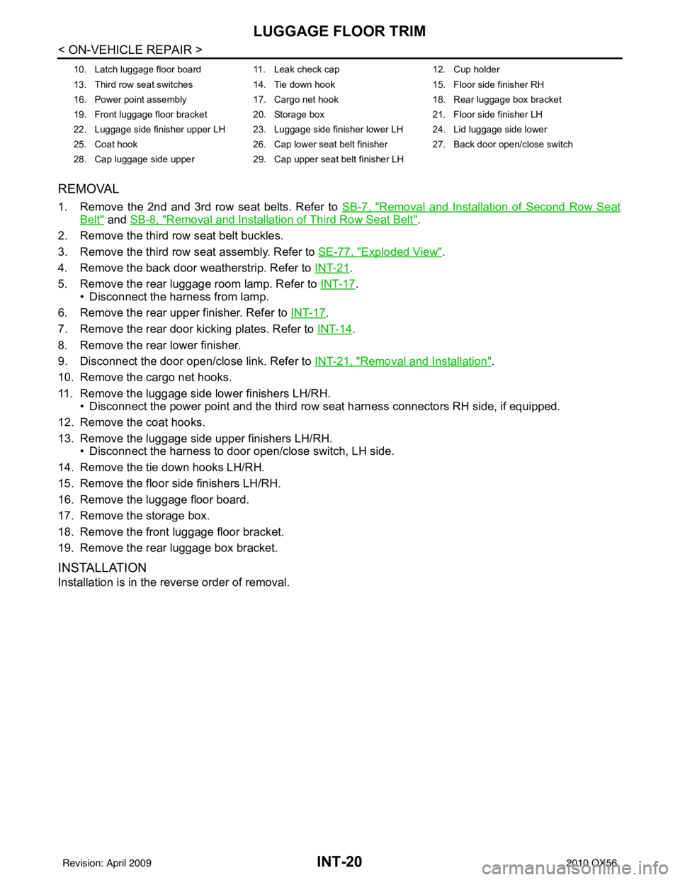
10. Latch luggage floor board 11. Leak check cap 12. Cup holder
13. Third row seat switches 14. Tie down hook 15. Floor side finisher RH
16. Power point assembly 17. Cargo net hook 18. Rear luggage box bracket
19. Front luggage floor bracket 20. Storage box 21. Floor side finisher LH
22. Luggage side finisher upper LH 23. Luggage side finisher lower LH 24. Lid luggage side lower
25. Coat hook 26. Cap lower seat belt finisher 27. Back door open/close switch
28. Cap luggage side upper 29. Cap upper seat belt finisher LH
Revision: April 20092010 QX56
Page 2573 of 4210
BACK DOOR TRIMINT-21
< ON-VEHICLE REPAIR >
C
DE
F
G H
I
K L
M A
B
INT
N
O P
BACK DOOR TRIM
Removal and InstallationINFOID:0000000005147354
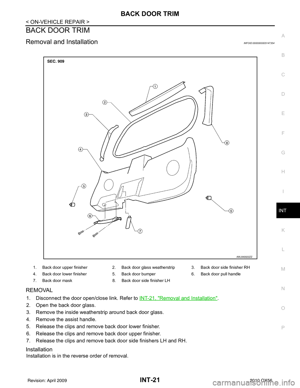
REMOVAL
1. Disconnect the door open/close link. Refer to INT-21, "Removal and Installation".
2. Open the back door glass.
3. Remove the inside weatherstrip around back door glass.
4. Remove the assist handle.
5. Release the clips and remove back door lower finisher.
6. Release the clips and remove back door upper finisher.
7. Release the clips and remove back door side finishers LH and RH.
Installation
Installation is in the reverse order of removal.
1. Back door upper finisher 2. Back door glass weatherstrip 3. Back door side finisher RH
4. Back door lower finisher 5. Back door bumper6. Back door pull handle
7. Back door mask 8. Back door side finisher LH
AWJIA0022ZZ
Revision: April 20092010 QX56
Page 2574 of 4210
IP-1
BODY INTERIOR
C
DE
F
G H
I
K L
M
SECTION IP
A
B
IP
N
O P
CONTENTS
INSTRUMENT PANEL
PRECAUTION ....... ........................................2
PRECAUTIONS .............................................. .....2
Precaution for Supplemental Restraint System
(SRS) "AIR BAG" and "SEAT BELT PRE-TEN-
SIONER" ............................................................. ......
2
Precaution Necessary for Steering Wheel Rota-
tion After Battery Disconnect ............................... ......
2
PREPARATION ............................................4
PREPARATION .............................................. .....4
Special Service Tool ........................................... ......4
Commercial Service Tool ..........................................4
SYMPTOM DIAGNOSIS ...............................5
SQUEAK AND RATTLE TROUBLE DIAG-
NOSES ........................ ........................................
5
Work Flow ........................................................... ......5
Generic Squeak and Rattle Troubleshooting ............7
Diagnostic Worksheet ...............................................9
ON-VEHICLE REPAIR .................................11
INSTRUMENT PANEL ASSEMBLY .............. ....11
Exploded View .................................................... ....11
Removal and Installation .........................................12
CLUSTER LID A ............................................. ....14
Exploded View .................................................... ....14
Removal and Installation .........................................14
CLUSTER LID C ...............................................15
Exploded View ..................................................... ....15
Removal and Installation .........................................15
INSTRUMENT LOWER PANEL RH AND
GLOVE BOX .....................................................
17
Exploded View .........................................................17
Removal and Installation .........................................17
INSTRUMENT UPPER PANEL RH ..................18
Exploded View .........................................................18
Removal and Installation .........................................18
A/T FINISHER ...................................................19
Removal and Installation .........................................19
FRONT CENTER CONSOLE ............................20
Exploded View .........................................................20
Removal and Installation .........................................20
REAR CENTER CONSOLE ..............................21
Removal and Installation .........................................21
DISASSEMBLY AND ASSEMBLY ..............22
FRONT CENTER CONSOLE ............................22
Exploded View ..................................................... ....22
Disassembly and Assembly .....................................23
REAR CENTER CONSOLE ..............................24
Exploded View .........................................................24
Disassembly and Assembly .....................................25
Revision: April 20092010 QX56
Page 2585 of 4210
IP-12
< ON-VEHICLE REPAIR >
INSTRUMENT PANEL ASSEMBLY
Removal and Installation
INFOID:0000000005147362
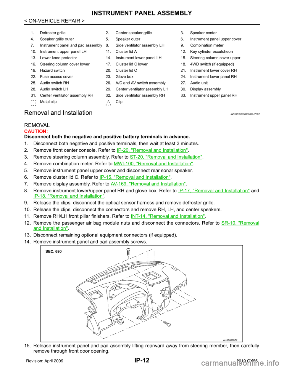
REMOVAL
CAUTION:
Disconnect both the negative and po sitive battery terminals in advance.
1. Disconnect both negative and positive termi nals, then wait at least 3 minutes.
2. Remove front center console. Refer to IP-20, "
Removal and Installation".
3. Remove steering column assembly. Refer to ST-20, "
Removal and Installation".
4. Remove combination meter. Refer to MWI-100, "
Removal and Installation".
5. Remove instrument panel upper cover and disconnect rear sonar speaker.
6. Remove cluster lid C. Refer to IP-15, "
Removal and Installation".
7. Remove display assembly. Refer to AV-169, "
Removal and Installation".
8. Remove instrument lower/upper panel RH and glove box. Refer to IP-17, "
Removal and Installation" and
IP-18, "
Removal and Installation".
9. Release the clips, disconnect the optical sensor harness and remove defroster grille.
10. Release the clips, disconnect the connecto rs and remove RH, LH, and center speakers.
11. Remove RH/LH front pillar finishers. Refer to INT-14, "
Removal and Installation".
12. Remove the passenger air bag module nuts and disconnect the connectors. Refer to SR-10, "
Removal
and Installation".
13. Disconnect remaining optional equipment connectors (if equipped).
14. Remove instrument panel and pad assembly screws.
15. Release instrument panel and pad assembly lifting rearward away from steering member, then carefully remove through front door opening.
1. Defroster grille 2. Center speaker grille3. Speaker center
4. Speaker grille outer 5. Speaker outer6. Instrument panel upper cover
7. Instrument panel and pad assembly 8. Side ventilator assembly LH 9. Combination meter
10. Instrument upper panel LH 11. Cluster lid A 12. Key cylinder escutcheon
13. Lower knee protector 14. Instrument lower panel LH 15. Steering column cover upper
16. Steering column cover lower 17. Cluster lid C lower 18. 4WD switch (if equipped)
19. Hazard switch 20. Cluster lid C21. Instrument lower cover RH
22. Fuse access cover 23. Glove box 24. Instrument lower panel RH
25. Audio switch RH 26. A/C and AV switch assembly 27. Audio unit
28. Audio switch LH 29. Center ventilator assembly LH 30. Display assembly
31. Center ventilator assembly RH 32. Side ventilator assembly RH 33. Instrument upper panel RH Metal clip Clip
ALJIA0083ZZ
Revision: April 20092010 QX56
Page 2587 of 4210
IP-14
< ON-VEHICLE REPAIR >
CLUSTER LID A
CLUSTER LID A
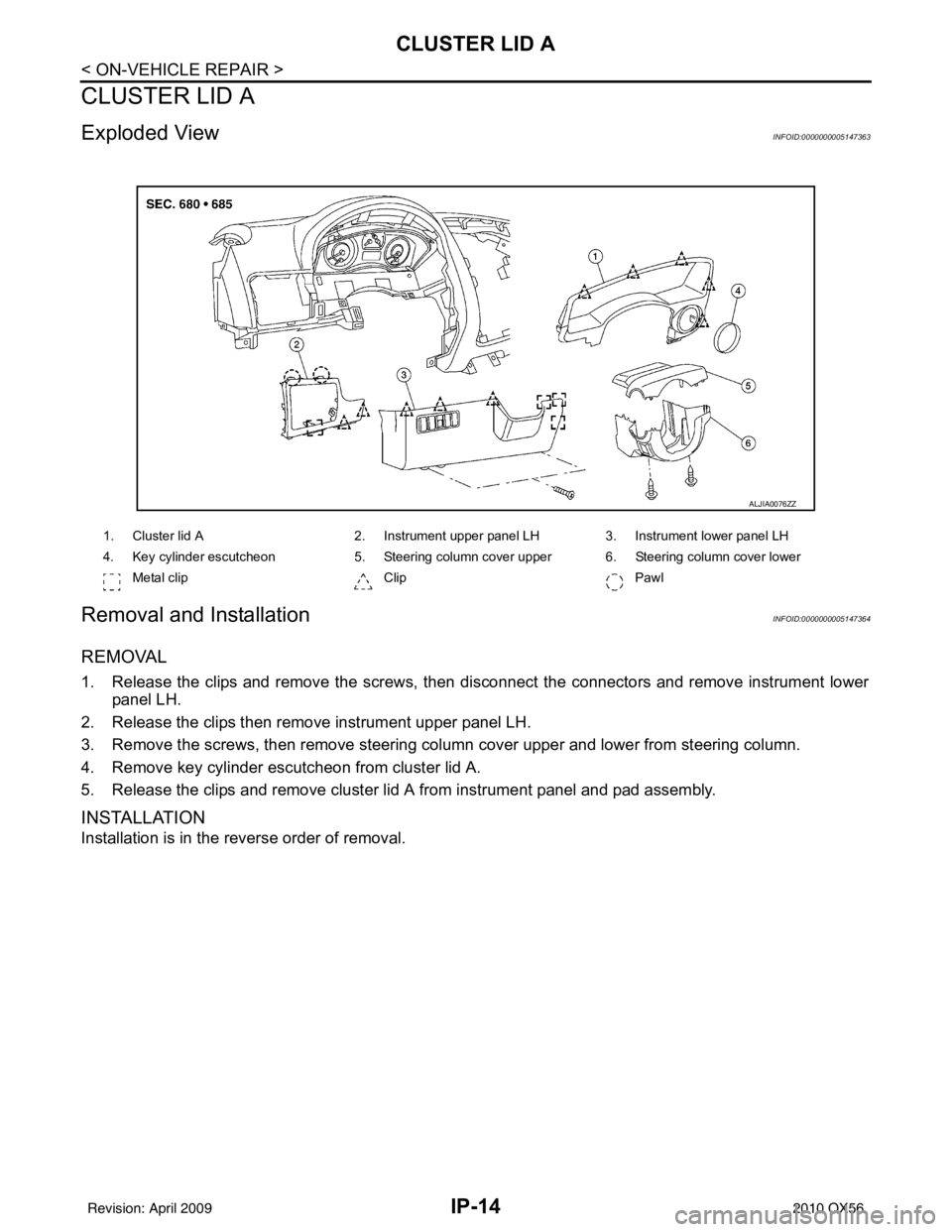
Exploded ViewINFOID:0000000005147363
Removal and InstallationINFOID:0000000005147364
REMOVAL
1. Release the clips and remove the screws, then disconnect the connectors and remove instrument lowerpanel LH.
2. Release the clips then remove instrument upper panel LH.
3. Remove the screws, then remove steering column cover upper and lower from steering column.
4. Remove key cylinder escutcheon from cluster lid A.
5. Release the clips and remove cluster lid A from instrument panel and pad assembly.
INSTALLATION
Installation is in the reverse order of removal.
ALJIA0076ZZ
1. Cluster lid A 2. Instrument upper panel LH 3. Instrument lower panel LH
4. Key cylinder escutcheon 5. Steering column cover upper 6. Steering column cover lower
Metal clip Clip Pawl
Revision: April 20092010 QX56