Page 2780 of 4210
MWI-18
< FUNCTION DIAGNOSIS >
METER SYSTEM
SHIFT POSITION INDICATOR : Component Parts Location
INFOID:0000000005146060
SHIFT POSITION INDICATOR : Component DescriptionINFOID:0000000005146061
WARNING LAMPS/INDICATOR LAMPS
WARNING LAMPS/INDICATOR LAMPS : System DiagramINFOID:0000000005146062
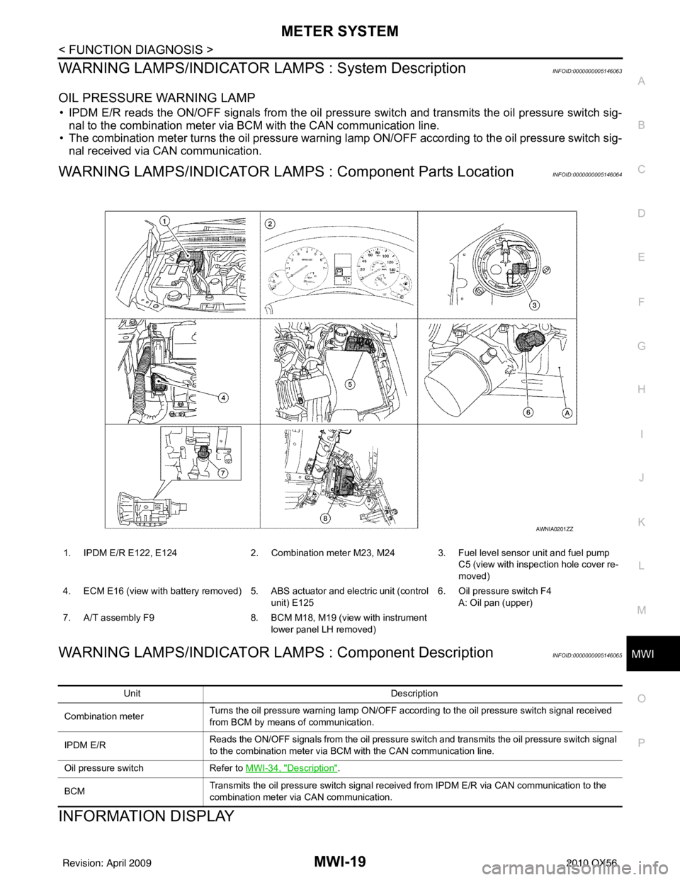
1. IPDM E/R E122, E124 2. Combination meter M23, M24 3. Fuel level sensor unit and fuel pump
C5 (view with inspection hole cover re-
moved)
4. ECM E16 (view with battery removed) 5. ABS actuator and electric unit (control
unit) E125 6. Oil pressure switch F4
A: Oil pan (upper)
7. A/T assembly F9 8. BCM M18, M19 (view with instrument
lower panel LH removed)
AWNIA0201ZZ
Unit Description
Combination meter Displays the shift position on the information display using shift position signal received from TCM.
TCM Transmits the shift position signal to the combination meter via CAN communication.
JSNIA0449GB
Revision: April 20092010 QX56
Page 2781 of 4210

MWI
METER SYSTEMMWI-19
< FUNCTION DIAGNOSIS >
C
DE
F
G H
I
J
K L
M B A
O P
WARNING LAMPS/INDICATOR LAMPS : System DescriptionINFOID:0000000005146063
OIL PRESSURE WARNING LAMP
• IPDM E/R reads the ON/OFF signals from the oil pressure switch and transmits the oil pressure switch sig-
nal to the combination meter via BCM with the CAN communication line.
• The combination meter turns the oil pressure warning lamp ON/OFF according to the oil pressure switch sig- nal received via CAN communication.
WARNING LAMPS/INDICATOR LAMPS : Component Parts LocationINFOID:0000000005146064
WARNING LAMPS/INDICATOR LAMPS : Component DescriptionINFOID:0000000005146065
INFORMATION DISPLAY
1. IPDM E/R E122, E124 2. Combination meter M23, M24 3. Fuel level sensor unit and fuel pump
C5 (view with inspection hole cover re-
moved)
4. ECM E16 (view with battery removed) 5. ABS actuator and electric unit (control unit) E1256. Oil pressure switch F4
A: Oil pan (upper)
7. A/T assembly F9 8. BCM M18, M19 (view with instrument
lower panel LH removed)
AWNIA0201ZZ
Unit Description
Combination meter Turns the oil pressure warning lamp ON/OFF according to the oil pressure switch signal received
from BCM by means of communication.
IPDM E/R Reads the ON/OFF signals from the oil pressure switch and transmits the oil pressure switch signal
to the combination meter via BCM with the CAN communication line.
Oil pressure switch Refer to MWI-34, "
Description".
BCM Transmits the oil pressure switch signal received from IPDM E/R via CAN communication to the
combination meter via CAN communication.
Revision: April 20092010 QX56
Page 2783 of 4210

MWI
METER SYSTEMMWI-21
< FUNCTION DIAGNOSIS >
C
DE
F
G H
I
J
K L
M B A
O P
INFORMATION DISPLAY : Co mponent Parts LocationINFOID:0000000005146068
INFORMATION DISPLAY : Component DescriptionINFOID:0000000005146069
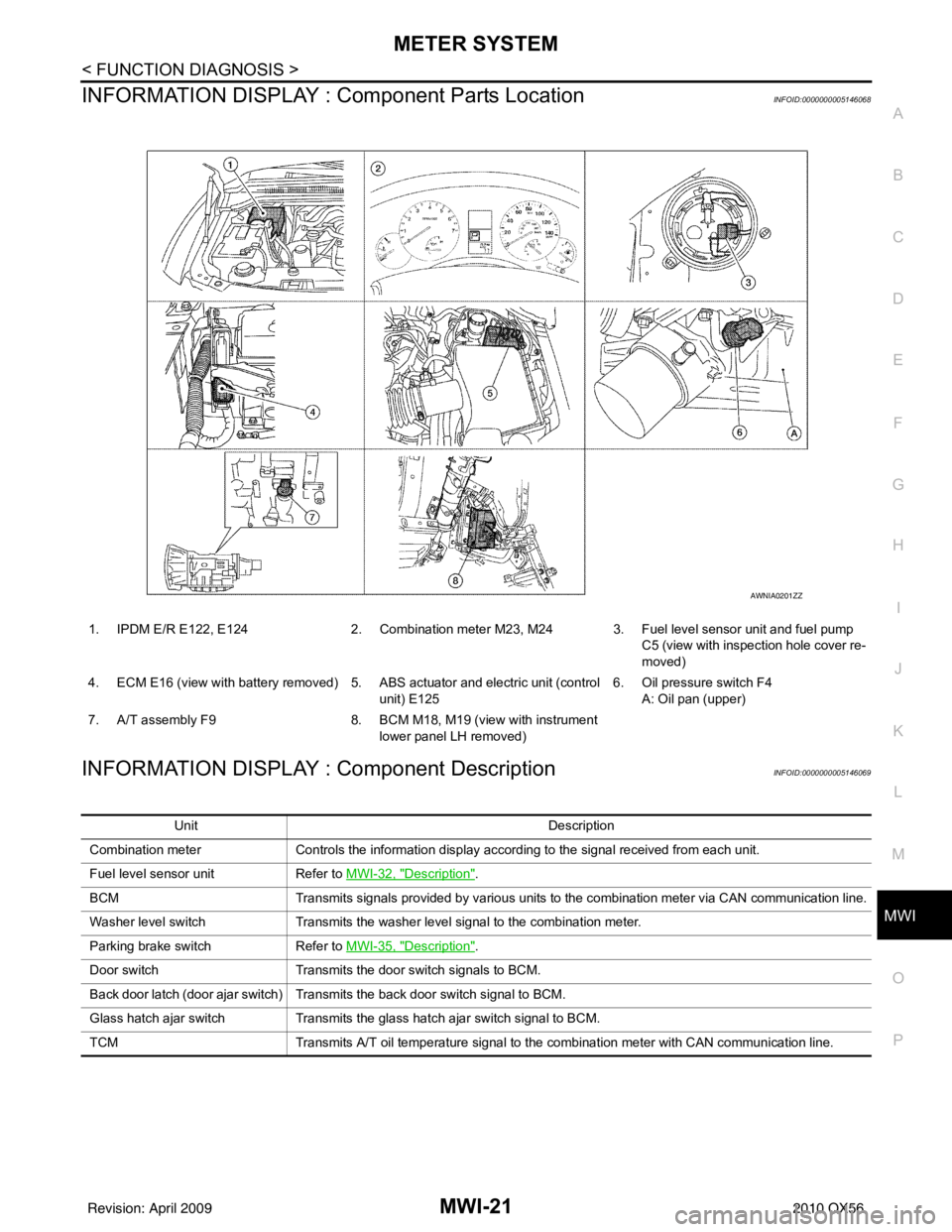
1. IPDM E/R E122, E124 2. Combination meter M23, M24 3. Fuel level sensor unit and fuel pump
C5 (view with inspection hole cover re-
moved)
4. ECM E16 (view with battery removed) 5. ABS actuator and electric unit (control unit) E1256. Oil pressure switch F4
A: Oil pan (upper)
7. A/T assembly F9 8. BCM M18, M19 (view with instrument
lower panel LH removed)
AWNIA0201ZZ
Unit Description
Combination meter Controls the information display according to the signal received from each unit.
Fuel level sensor unit Refer to MWI-32, "
Description".
BCM Transmits signals provided by various units to the combination meter via CAN communication line.
Washer level switch Transmits the washer level signal to the combination meter.
Parking brake switch Refer to MWI-35, "
Description".
Door switch Transmits the door switch signals to BCM.
Back door latch (door ajar switch) Transmits the back door switch signal to BCM.
Glass hatch ajar switch Transmits the glass hatch ajar switch signal to BCM.
TCM Transmits A/T oil temperature signal to the combination meter with CAN communication line.
Revision: April 20092010 QX56
Page 2862 of 4210
MWI-100
< ON-VEHICLE REPAIR >
COMBINATION METER
ON-VEHICLE REPAIR
COMBINATION METER
Removal and InstallationINFOID:0000000005146131
REMOVAL
1. Disconnect battery negative terminal.
2. Remove the cluster lid A. Refer to IP-14, "
Removal and Installation".
3. Remove the combination meter lower screws (A), using power tool.
4. Remove the combination meter upper screws, using power tool, and pull out the combination meter.
5. Disconnect the combination meter connectors, and remove the combination meter.
INSTALLATION
Installation is in the reverse order of removal.
ALNIA0283ZZ
Revision: April 20092010 QX56
Page 2910 of 4210
PCS
IPDM E/R (INTELLIGENT POWER DISTRIBUTION MODULE ENGINE ROOM)
PCS-35
< REMOVAL AND INSTALLATION > [IPDM E/R]
C
D
E
F
G H
I
J
K L
B A
O P
N
REMOVAL AND INSTALLATION
IPDM E/R (INTELLIGENT POWER
DISTRIBUTION MODULE ENGINE
ROOM)
Removal and Installation of IPDM E/RINFOID:0000000005146519
REMOVAL
1. Disconnect negative battery cable.
2. Remove IPDM E/R upper cover.
3. Release 2 clips and pull IPDM E/R up from case.
4. Disconnect IPDM E/R connectors and remove the IPDM E/R.
INSTALLATION
Installation is in the reverse order of removal.
WKIA1454E
WKIA1696E
Revision: April 20092010 QX56
Page 3105 of 4210
PWC-120
< ON-VEHICLE REPAIR >
REAR POWER VENT WINDOW SWITCH
REAR POWER VENT WINDOW SWITCH
Removal and InstallationINFOID:0000000005268493
REMOVAL
1. Remove the instrument lower panel LH, refer to IP-14, "Removal and Installation".
2. Using a suitable tool, release the upper and lower tabs , then remove the rear power vent window switch.
INSTALLATION
Installation is in the reverse order of removal.
1. Rear power vent window switch 2. Instrument lower panel LH Tab
ALKIA1619ZZ
Revision: April 20092010 QX56
Page 3197 of 4210
RSU-10
< ON-VEHICLE REPAIR >
REAR SUSPENSION ASSEMBLY
Rear Load Leveling Air Suspension System
13. Coil spring14. Upper rubber seat15. Rear suspension member
16. Spare tire bracket 17. Bound bumper Front
AWEIA0054GB
1. Rear load leveling air suspension
hose, RH 2. Shock absorber, RH
3. Height sensor
4. Rear load leveling air suspension hose, LH 5. Shock absorber, LH
6. Rear load leveling air suspension
compressor assembly
Front
Revision: April 20092010 QX56
Page 3199 of 4210

RSU-12
< REMOVAL AND INSTALLATION >
REAR SUSPENSION MEMBER
Rear Load Leveling Air Suspension System
REMOVAL
1. Use the CONSULT-III “EXHAUST SOLENOID” active test to release the air pressure from the rear load
leveling air suspension system.
2. Disconnect the electrical connectors for the height sensor and the rear load leveling air suspension com-
pressor assembly.
3. Unclip the rubber cover to access the rear load leveling air suspension compressor assembly.
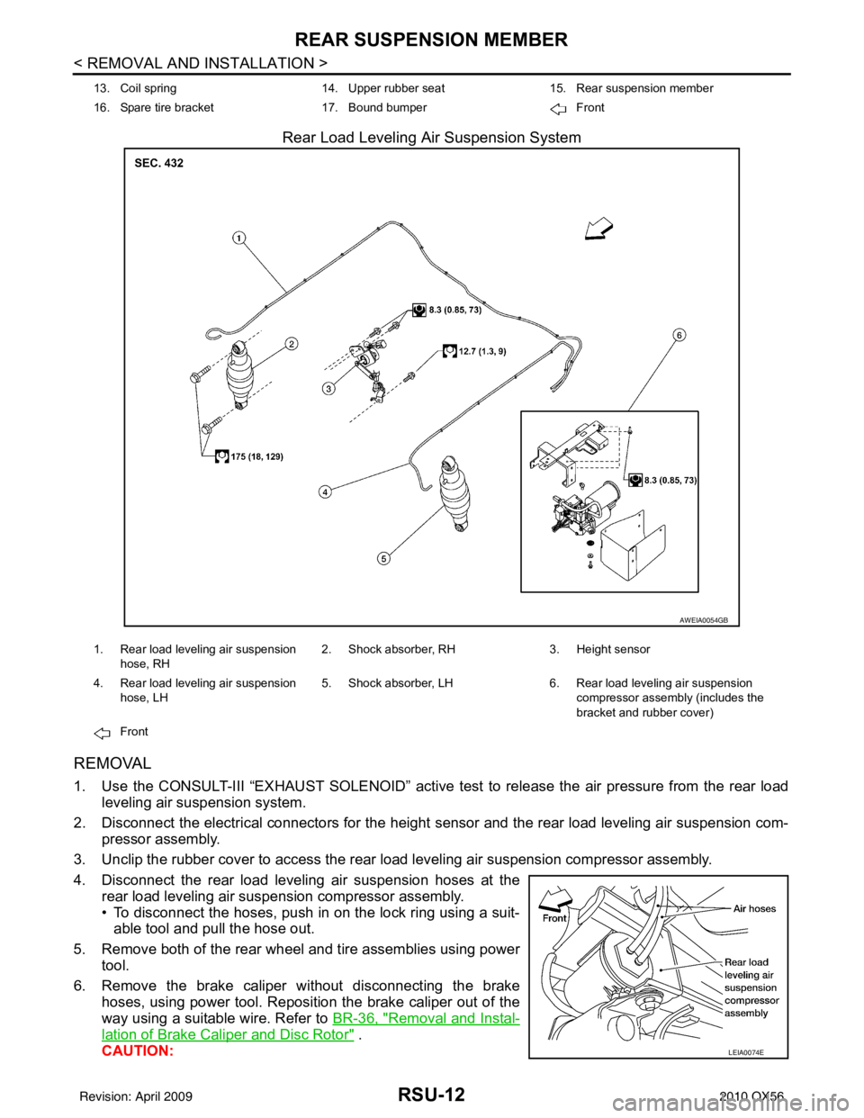
4. Disconnect the rear load leveling air suspension hoses at the rear load leveling air suspension compressor assembly.
• To disconnect the hoses, push in on the lock ring using a suit-able tool and pull the hose out.
5. Remove both of the rear wheel and tire assemblies using power tool.
6. Remove the brake caliper without disconnecting the brake hoses, using power tool. Reposition the brake caliper out of the
way using a suitable wire. Refer to BR-36, "
Removal and Instal-
lation of Brake Caliper and Disc Rotor" .
CAUTION:
13. Coil spring 14. Upper rubber seat15. Rear suspension member
16. Spare tire bracket 17. Bound bumper Front
AWEIA0054GB
1. Rear load leveling air suspension
hose, RH 2. Shock absorber, RH
3. Height sensor
4. Rear load leveling air suspension hose, LH 5. Shock absorber, LH
6. Rear load leveling air suspension
compressor assembly (includes the
bracket and rubber cover)
Front
LEIA0074E
Revision: April 20092010 QX56