Page 3238 of 4210

SCS-6
< FUNCTION DIAGNOSIS >
SUSPENSION CONTROL SYSTEM
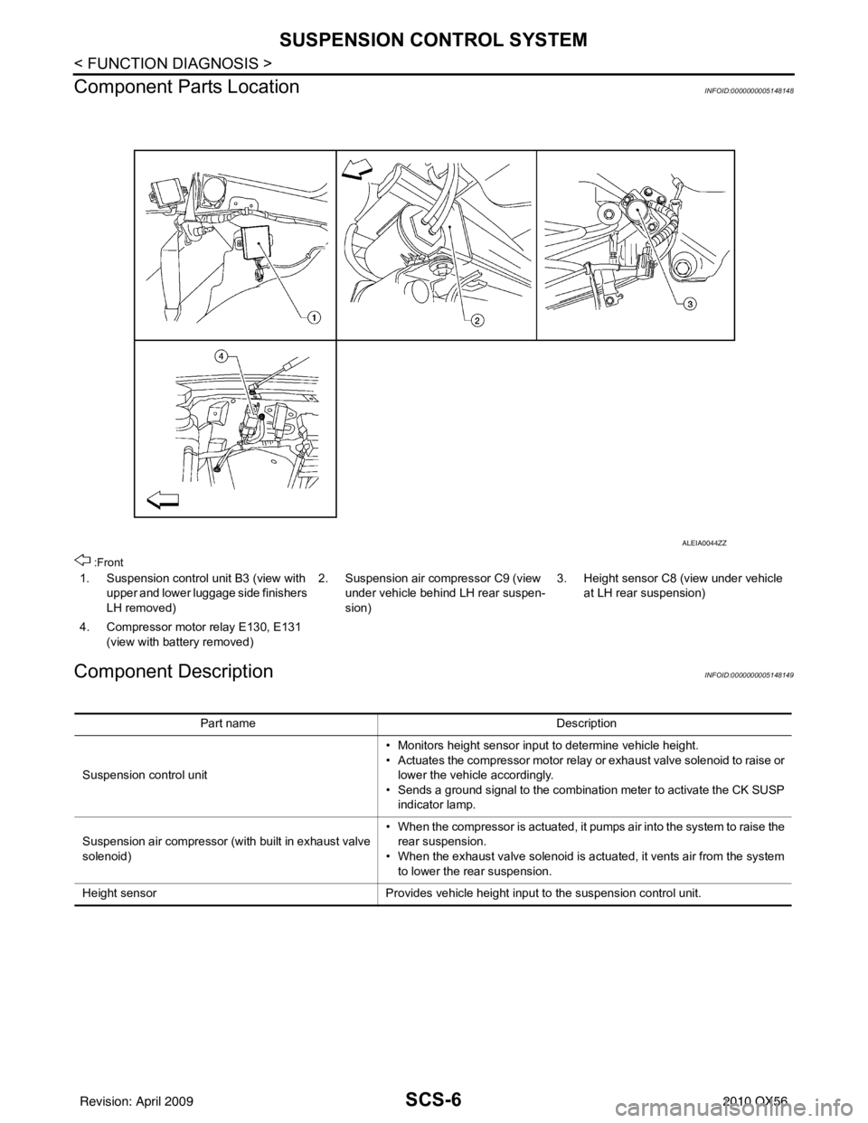
Component Parts Location
INFOID:0000000005148148
:Front
Component DescriptionINFOID:0000000005148149
1. Suspension control unit B3 (view with upper and lower luggage side finishers
LH removed) 2. Suspension air compressor C9 (view
under vehicle behind LH rear suspen-
sion) 3. Height sensor C8 (view under vehicle
at LH rear suspension)
4. Compressor motor relay E130, E131 (view with battery removed)
ALEIA0044ZZ
Part name Description
Suspension control unit • Monitors height sensor input to determine vehicle height.
• Actuates the compressor motor relay or exhaust valve solenoid to raise or
lower the vehicle accordingly.
• Sends a ground signal to the combination meter to activate the CK SUSP indicator lamp.
Suspension air compressor (with built in exhaust valve
solenoid) • When the compressor is actuated, it pumps air into the system to raise the
rear suspension.
• When the exhaust valve solenoid is actuated, it vents air from the system to lower the rear suspension.
Height sensor Provides vehicle height input to the suspension control unit.
Revision: April 20092010 QX56
Page 3343 of 4210
FRONT SEATSE-71
< DISASSEMBLY AND ASSEMBLY >
C
DE
F
G H
I
K L
M A
B
SE
N
O P
Installation
Installation is in the reverse order of removal.
PASSENGER SEATBACK BOARD - HARD SEATBACK
Removal
1. The seatback board is attached to
the seat frame with the follow-
ing:
• 2 top tabs (A)
• 2 side tabs (B)
• 2 bottom clips (C) (must be replaced)
2. Move seat to forward position.
3. Hold the seatback board as shown and pull the bottom of the seatback board away from the seat back frame.
4. Pull the middle part of the seatback board to disengage the side tabs (B) from the seatback frame.
5. Lift the upper part of the seatback board to disengage the top tabs from the seatback frame.
Installation
Installation is in the reverse order of removal.
ALIIA0395ZZ
ALIIA0370ZZ
ALIIA0371ZZ
Revision: April 20092010 QX56
Page 3522 of 4210
SN-50
< REMOVAL AND INSTALLATION >
SONAR CONTROL UNIT
SONAR CONTROL UNIT
Removal and InstallationINFOID:0000000005146217
Removal
1. Remove the luggage side finisher lower and upper LH. Refer to INT-19, "Removal and Installation".
2. Disconnect the sonar control unit electrical connectors.
3. Remove the bolt, then remove the sonar control unit. • Front and rear sonar control unit (1)
• Rear sonar control unit (1)
INSTALLATION
Installation is in the reverse order of removal.
AWNIA1412ZZ
AWNIA1901ZZ
Revision: April 20092010 QX56
Page 3523 of 4210
SN
BUZZERSN-51
< REMOVAL AND INSTALLATION >
C
DE
F
G H
I
J
K L
M B A
O P
BUZZER
Removal and InstallationINFOID:0000000005146218
FRONT BUZZER
Removal
1. Remove the instrument panel upper cover. Refer to IP-11, "Exploded View".
2. Remove the two bolts (1), disconnect the connector (2) and remove the front buzzer.
Installation
Installation is in the reverse order of removal.
REAR BUZZER
NOTE:
Rear buzzer location used only for vehicles equipped with both front and rear sonar systems.
Removal
1. Partially remove the rear headliner. Refer to INT-17, "Removal and Installation".
2. Release the buzzer from the bracket, disconnect the connector and remove the buzzer.
Installation
Installation is in the reverse order of removal.
ALNIA0425ZZ
Revision: April 20092010 QX56
Page 3530 of 4210

SPIRAL CABLESR-7
< ON-VEHICLE REPAIR >
C
DE
F
G
I
J
K L
M A
B
SR
N
O P
SPIRAL CABLE
Removal and InstallationINFOID:0000000005147758
REMOVAL
CAUTION:
• Before servicing the SRS, turn ignition switch OFF, disconnect both battery terminals and wait at
least three minutes.
• When servicing the SRS, do not work from directly in front of air bag module.
1. Disconnect both the negative and positive battery te rminals, then wait at least three minutes.
2. Remove the steering wheel. Refer to ST-18, "
Removal and Installation".
3. Remove the instrument lower panel LH. Refer to IP-14, "
Exploded View".
4. Remove the column cover upper and lower.
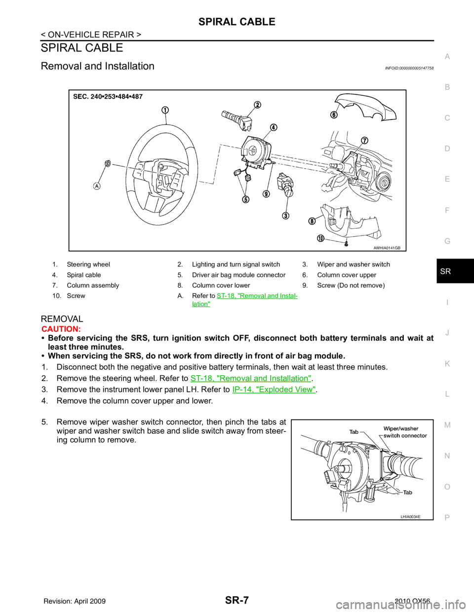
5. Remove wiper washer switch connector, then pinch the tabs at wiper and washer switch base and slide switch away from steer-
ing column to remove.
1. Steering wheel 2. Lighting and turn signal switch 3. Wiper and washer switch
4. Spiral cable 5. Driver air bag module connector 6. Column cover upper
7. Column assembly 8. Column cover lower9. Screw (Do not remove)
10. Screw A. Refer to ST-18, "
Removal and Instal-
lation"
AWHIA0141GB
LHIA0034E
Revision: April 20092010 QX56
Page 3538 of 4210

SIDE AIR BAG (SATELLITE) SENSORSR-15
< ON-VEHICLE REPAIR >
C
DE
F
G
I
J
K L
M A
B
SR
N
O P
SIDE AIR BAG (S ATELLITE) SENSOR
Removal and InstallationINFOID:0000000005147762
REMOVAL
CAUTION:
• Before servicing the SRS, turn the ignition switch off, disconnect both battery terminals and wait at
least three minutes.
• Do not use old nuts after removal; replace with new nuts.
• Check side air bag (satellite) sensor to make sure it is free of deformities, dents, cracks or rust. If it
shows any visible signs of da mage, replace it with new one.
• Do not disassemble side air bag (satellite) sensor.
• Replace side air bag (satellite ) sensor if it has been dropped or sustained an impact.
1. Disconnect both the negative and positive battery te rminals, then wait at least three minutes.
2. Remove seat belt retractor and belt assembly anchor bolt and retractor bolt upper, then set assembly
aside. Refer to SB-4, "
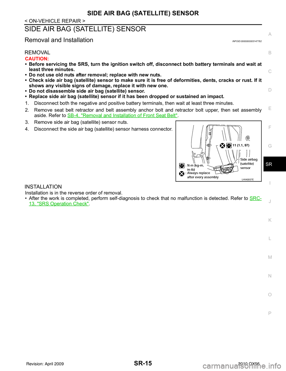
Removal and Installation of Front Seat Belt".
3. Remove side air bag (satellite) sensor nuts.
4. Disconnect the side air bag (satellite) sensor harness connector.
INSTALLATION
Installation is in the reverse order of removal.
• After the work is completed, perform self-diagnosis to check that no malfunction is detected. Refer to SRC-
13, "SRS Operation Check".
LHIA0057E
Revision: April 20092010 QX56
Page 3658 of 4210

ST-20
< REMOVAL AND INSTALLATION >
STEERING COLUMN
STEERING COLUMN
Removal and InstallationINFOID:0000000005147872
CAUTION:
• Any time the ignition switch has been disconnecter, removed or installed, the keys must be re-rege-
stered in the BCM. Refer toConsult-III operations IVIS/NVIS.
• Do not exert any load or impact in the axial dir ection immediately before or after column removal.
• Do not to move steering gear during removal of steering column assembly.
REMOVAL
1. Remove combination switch and spiral cable from steering column assembly. Refer to SR-7, "Removal
and Installation".
2. Remove the tilt motor and tilt sensor. Refer to ST-19, "
Removal and Installation".
3. Remove steering column cover. Refer to ST-20, "
Removal and Installation".
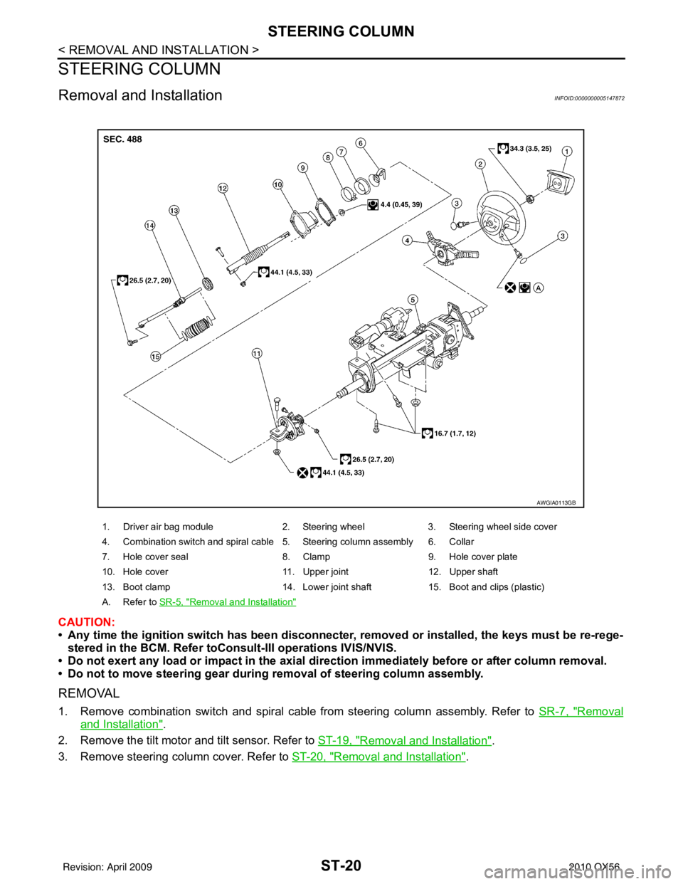
1. Driver air bag module2. Steering wheel3. Steering wheel side cover
4. Combination switch and spiral cable 5. Steering column assembly 6. Collar
7. Hole cover seal 8. Clamp9. Hole cover plate
10. Hole cover 11. Upper joint12. Upper shaft
13. Boot clamp 14. Lower joint shaft15. Boot and clips (plastic)
A. Refer to SR-5, "
Removal and Installation"
AWGIA0113GB
Revision: April 20092010 QX56
Page 3659 of 4210
STEERING COLUMNST-21
< REMOVAL AND INSTALLATION >
C
DE
F
H I
J
K L
M A
B
ST
N
O P
4. Remove lock nut and bolt, then separate upper shaft from upper joint.
5. Remove two nuts and two bolts, then remove steering column assembly from steering member.
6. Remove hole cover seal and clamp.
7. Remove nuts, then remove hole cover from dash panel.
8. Raise vehicle, then remove bolt (lower side) of lower joint shaft and remove lower joint shaft and upper shaft as an assembly.
INSPECTION AFTER REMOVAL
• Check for damage to steering column jacket tube. If damage is found, replace steering column with new
one.
• If vehicle has been in a collision, check column length (L), (L
1) and (L2) as shown. If out of specification,
replace steering column with new one.
LGIA0027E
LGIA0028E
LGIA0029E
Steering column length
(L) : Refer to ST-35, "
Steering Column"
(L1): Refer to
ST-35, "Steering Column"
(L2): Refer to
ST-35, "Steering Column"
WGIA0080E
Revision: April 20092010 QX56