2010 INFINITI QX56 glove box
[x] Cancel search: glove boxPage 878 of 4210
![INFINITI QX56 2010 Factory Service Manual DLK-44
< FUNCTION DIAGNOSIS >[WITH INTELLIGENT KEY SYSTEM]
KEY REMINDER FUNCTION
KEY REMINDER FUNCTION
System DescriptionINFOID:0000000005146893
Key reminder is the function that prevents the key from INFINITI QX56 2010 Factory Service Manual DLK-44
< FUNCTION DIAGNOSIS >[WITH INTELLIGENT KEY SYSTEM]
KEY REMINDER FUNCTION
KEY REMINDER FUNCTION
System DescriptionINFOID:0000000005146893
Key reminder is the function that prevents the key from](/manual-img/42/57032/w960_57032-877.png)
DLK-44
< FUNCTION DIAGNOSIS >[WITH INTELLIGENT KEY SYSTEM]
KEY REMINDER FUNCTION
KEY REMINDER FUNCTION
System DescriptionINFOID:0000000005146893
Key reminder is the function that prevents the key from being left in the vehicle.
Key reminder has the following 3 functions.
*:If the door closing impact shocks the door lock knob, or contacts against baggage with the door lock knob might activate the
door locks
accidentally but unlock operation will be performed in these cases.
CAUTION:
• The above function operates when the Intelligent Key is inside the vehicle. However, there may be
times when the Intelligent Key cannot be detected, an d this function will not operate when the Intelli-
gent Key is on the instrument panel, rear of vehic le, or in the glove box. Also, this system sometimes
does not operate if the Intelligent Key is in the door pocket for the open door.
• When the key reminder function is operated when the back door is open/closed and the buzzers
sound, if the following operations are performed, the key remind er function is cleared and buzzer
sounds are stopped.
- Remote controller door lock butt on operation of Intelligent Key
- Remote controller door unlock butt on operation of Intelligent Key
- When the liftgate is closed, the Intelligent Key is not inside the vehicle
- When any door is open
Key reminder function Operation condition Operation
Driver door closed* Right after driver side door is closed under the following conditions
• Door lock operation is performed
• Driver side door is opened
• Driver side door is in unlock state All doors unlock
Door is open or closed Right after all doors are closed under the following conditions
• Intelligent Key is inside the vehicle
• Any door is opened
• All doors are locked by door lock and unlock switch or door lock knob • All doors unlock
• Sounds Intelligent Key warning
buzzer
Back door is closed Right after back door is closed under the following conditions
• Intelligent Key is inside luggage compartment
• All doors are closed
• All doors are locked • Back door open
• Sounds Intelligent Key warning
buzzer
Revision: April 20092010 QX56
Page 2547 of 4210
INL-78
< ON-VEHICLE REPAIR >
INTERIOR ROOM LAMP
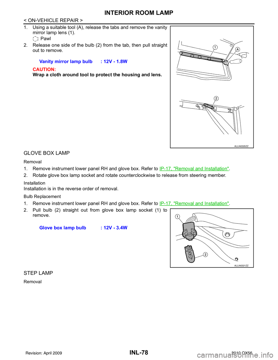
1. Using a suitable tool (A), release the tabs and remove the vanitymirror lamp lens (1).
: Pawl
2. Release one side of the bulb (2) from the tab, then pull straight out to remove.
CAUTION:
Wrap a cloth around tool to protect the housing and lens.
GLOVE BOX LAMP
Removal
1. Remove instrument lower panel RH and glove box. Refer to IP-17, "Removal and Installation".
2. Rotate glove box lamp socket and rotate counterclockwise to release from steering member.
Installation
Installation is in the reverse order of removal.
Bulb Replacement
1. Remove instrument lower panel RH and glove box. Refer to IP-17, "Removal and Installation".
2. Pull bulb (2) straight out from glove box lamp socket (1) to remove.
STEP LAMP
Removal
Vanity mirror lamp bulb : 12V - 1.8W
ALLIA0320ZZ
Glove box lamp bulb : 12V - 3.4W
ALLIA0321ZZ
Revision: April 20092010 QX56
Page 2552 of 4210

BULB SPECIFICATIONSINL-83
< SERVICE DATA AND SPECIFICATIONS (SDS)
C
DE
F
G H
I
J
K
M A
B
INL
N
O P
SERVICE DATA AND SPECIFICATIONS (SDS)
BULB SPECIFICATIONS
Interior Lamp/IlluminationINFOID:0000000005146756
*: Always check with the Parts Department for the latest parts information. Item
Wattage (W)*
Map Lamp 8
Vanity mirror lamp 1.32
Glove box lamp 3.4
Step lamp 3.8
Personal lamp 6
Footwell lamp 3.4
Cargo lamp 8
Console illumination lamp -
Revision: April 20092010 QX56
Page 2574 of 4210

IP-1
BODY INTERIOR
C
DE
F
G H
I
K L
M
SECTION IP
A
B
IP
N
O P
CONTENTS
INSTRUMENT PANEL
PRECAUTION ....... ........................................2
PRECAUTIONS .............................................. .....2
Precaution for Supplemental Restraint System
(SRS) "AIR BAG" and "SEAT BELT PRE-TEN-
SIONER" ............................................................. ......
2
Precaution Necessary for Steering Wheel Rota-
tion After Battery Disconnect ............................... ......
2
PREPARATION ............................................4
PREPARATION .............................................. .....4
Special Service Tool ........................................... ......4
Commercial Service Tool ..........................................4
SYMPTOM DIAGNOSIS ...............................5
SQUEAK AND RATTLE TROUBLE DIAG-
NOSES ........................ ........................................
5
Work Flow ........................................................... ......5
Generic Squeak and Rattle Troubleshooting ............7
Diagnostic Worksheet ...............................................9
ON-VEHICLE REPAIR .................................11
INSTRUMENT PANEL ASSEMBLY .............. ....11
Exploded View .................................................... ....11
Removal and Installation .........................................12
CLUSTER LID A ............................................. ....14
Exploded View .................................................... ....14
Removal and Installation .........................................14
CLUSTER LID C ...............................................15
Exploded View ..................................................... ....15
Removal and Installation .........................................15
INSTRUMENT LOWER PANEL RH AND
GLOVE BOX .....................................................
17
Exploded View .........................................................17
Removal and Installation .........................................17
INSTRUMENT UPPER PANEL RH ..................18
Exploded View .........................................................18
Removal and Installation .........................................18
A/T FINISHER ...................................................19
Removal and Installation .........................................19
FRONT CENTER CONSOLE ............................20
Exploded View .........................................................20
Removal and Installation .........................................20
REAR CENTER CONSOLE ..............................21
Removal and Installation .........................................21
DISASSEMBLY AND ASSEMBLY ..............22
FRONT CENTER CONSOLE ............................22
Exploded View ..................................................... ....22
Disassembly and Assembly .....................................23
REAR CENTER CONSOLE ..............................24
Exploded View .........................................................24
Disassembly and Assembly .....................................25
Revision: April 20092010 QX56
Page 2585 of 4210
IP-12
< ON-VEHICLE REPAIR >
INSTRUMENT PANEL ASSEMBLY
Removal and Installation
INFOID:0000000005147362
REMOVAL
CAUTION:
Disconnect both the negative and po sitive battery terminals in advance.
1. Disconnect both negative and positive termi nals, then wait at least 3 minutes.
2. Remove front center console. Refer to IP-20, "
Removal and Installation".
3. Remove steering column assembly. Refer to ST-20, "
Removal and Installation".
4. Remove combination meter. Refer to MWI-100, "
Removal and Installation".
5. Remove instrument panel upper cover and disconnect rear sonar speaker.
6. Remove cluster lid C. Refer to IP-15, "
Removal and Installation".
7. Remove display assembly. Refer to AV-169, "
Removal and Installation".
8. Remove instrument lower/upper panel RH and glove box. Refer to IP-17, "
Removal and Installation" and
IP-18, "
Removal and Installation".
9. Release the clips, disconnect the optical sensor harness and remove defroster grille.
10. Release the clips, disconnect the connecto rs and remove RH, LH, and center speakers.
11. Remove RH/LH front pillar finishers. Refer to INT-14, "
Removal and Installation".
12. Remove the passenger air bag module nuts and disconnect the connectors. Refer to SR-10, "
Removal
and Installation".
13. Disconnect remaining optional equipment connectors (if equipped).
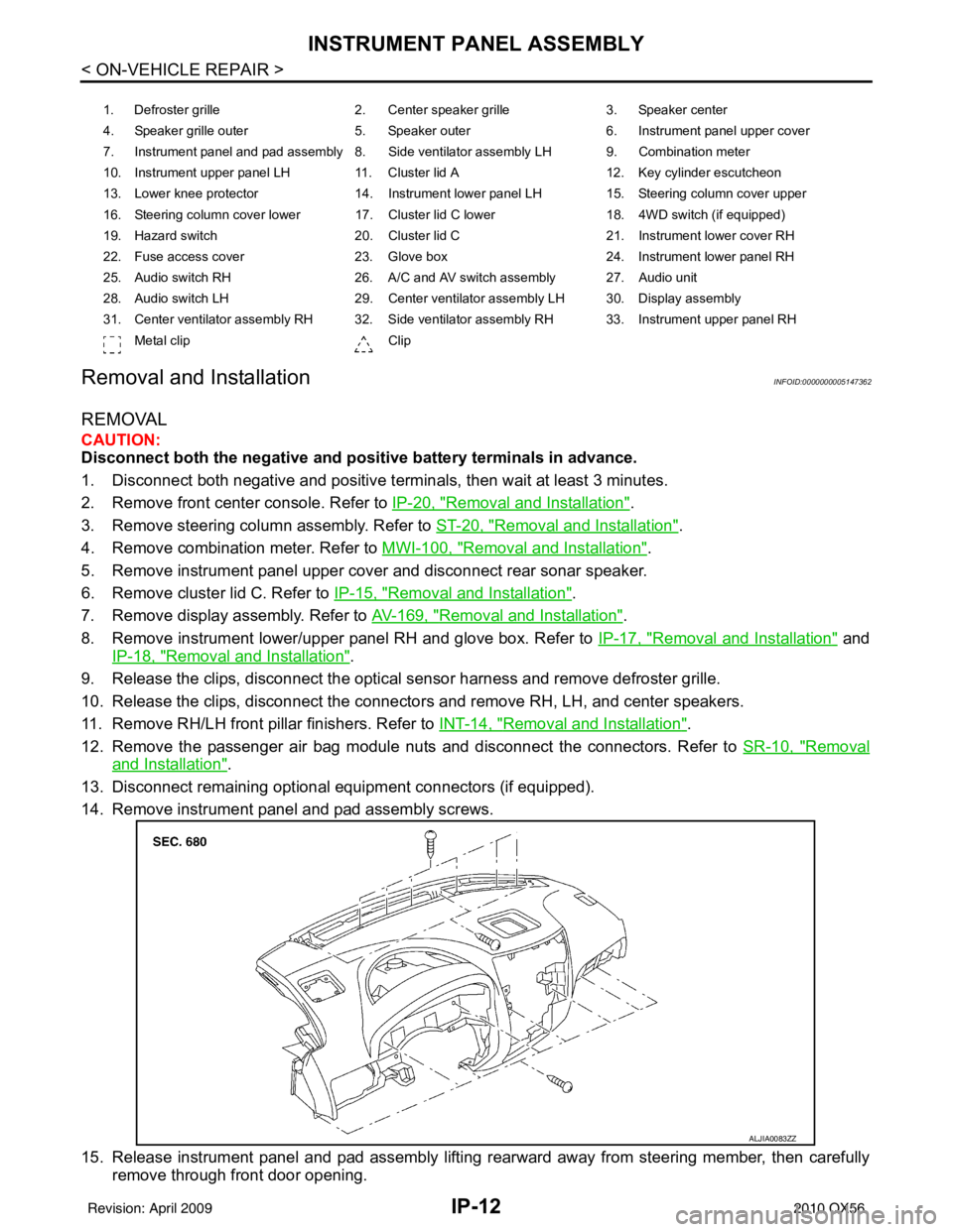
14. Remove instrument panel and pad assembly screws.
15. Release instrument panel and pad assembly lifting rearward away from steering member, then carefully remove through front door opening.
1. Defroster grille 2. Center speaker grille3. Speaker center
4. Speaker grille outer 5. Speaker outer6. Instrument panel upper cover
7. Instrument panel and pad assembly 8. Side ventilator assembly LH 9. Combination meter
10. Instrument upper panel LH 11. Cluster lid A 12. Key cylinder escutcheon
13. Lower knee protector 14. Instrument lower panel LH 15. Steering column cover upper
16. Steering column cover lower 17. Cluster lid C lower 18. 4WD switch (if equipped)
19. Hazard switch 20. Cluster lid C21. Instrument lower cover RH
22. Fuse access cover 23. Glove box 24. Instrument lower panel RH
25. Audio switch RH 26. A/C and AV switch assembly 27. Audio unit
28. Audio switch LH 29. Center ventilator assembly LH 30. Display assembly
31. Center ventilator assembly RH 32. Side ventilator assembly RH 33. Instrument upper panel RH Metal clip Clip
ALJIA0083ZZ
Revision: April 20092010 QX56
Page 2590 of 4210
INSTRUMENT LOWER PANEL RH AND GLOVE BOXIP-17
< ON-VEHICLE REPAIR >
C
DE
F
G H
I
K L
M A
B
IP
N
O P
INSTRUMENT LOWER PANE L RH AND GLOVE BOX
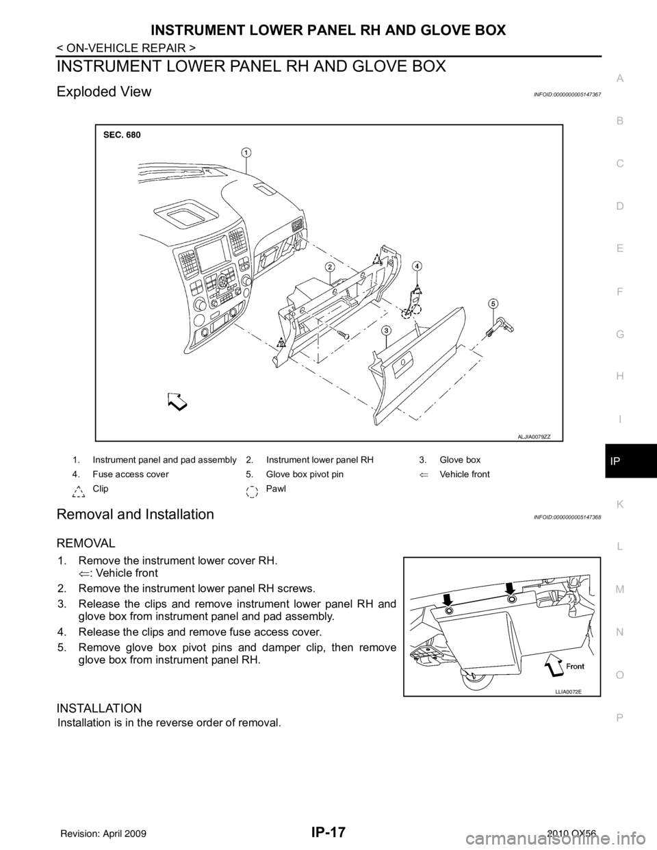
Exploded ViewINFOID:0000000005147367
Removal and InstallationINFOID:0000000005147368
REMOVAL
1. Remove the instrument lower cover RH.
⇐: Vehicle front
2. Remove the instrument lower panel RH screws.
3. Release the clips and remove instrument lower panel RH and glove box from instrument panel and pad assembly.
4. Release the clips and remove fuse access cover.
5. Remove glove box pivot pins and damper clip, then remove glove box from instrument panel RH.
INSTALLATION
Installation is in the reverse order of removal.
1. Instrument panel and pad assembly 2. Instrument lower panel RH 3. Glove box
4. Fuse access cover 5. Glove box pivot pin⇐Vehicle front
Clip Pawl
ALJIA0079ZZ
LLIA0072E
Revision: April 20092010 QX56
Page 2591 of 4210
IP-18
< ON-VEHICLE REPAIR >
INSTRUMENT UPPER PANEL RH
INSTRUMENT UPPER PANEL RH
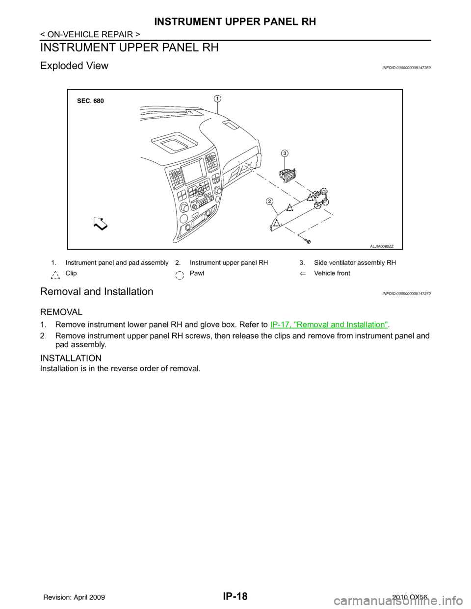
Exploded ViewINFOID:0000000005147369
Removal and InstallationINFOID:0000000005147370
REMOVAL
1. Remove instrument lower panel RH and glove box. Refer to IP-17, "Removal and Installation".
2. Remove instrument upper panel RH screws, then rel ease the clips and remove from instrument panel and
pad assembly.
INSTALLATION
Installation is in the reverse order of removal.
1. Instrument panel and pad assembly 2. Instrument upper panel RH 3. Side ventilator assembly RH
Clip Pawl ⇐Vehicle front
ALJIA0080ZZ
Revision: April 20092010 QX56
Page 2593 of 4210
IP-20
< ON-VEHICLE REPAIR >
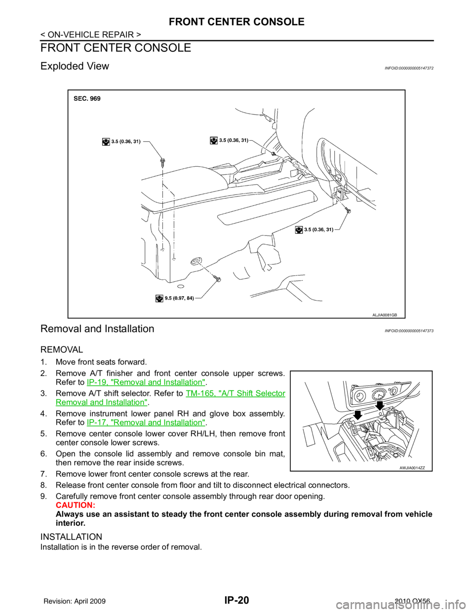
FRONT CENTER CONSOLE
FRONT CENTER CONSOLE
Exploded ViewINFOID:0000000005147372
Removal and InstallationINFOID:0000000005147373
REMOVAL
1. Move front seats forward.
2. Remove A/T finisher and front center console upper screws.Refer to IP-19, "
Removal and Installation".
3. Remove A/T shift selector. Refer to TM-165, "
A/T Shift Selector
Removal and Installation".
4. Remove instrument lower panel RH and glove box assembly. Refer to IP-17, "
Removal and Installation".
5. Remove center console lower cover RH/LH, then remove front center console lower screws.
6. Open the console lid assembly and remove console bin mat, then remove the rear inside screws.
7. Remove lower front center console screws at the rear.
8. Release front center console from floor and tilt to disconnect electrical connectors.
9. Carefully remove front center console assembly through rear door opening. CAUTION:
Always use an assistant to steady the front cen ter console assembly during removal from vehicle
interior.
INSTALLATION
Installation is in the reverse order of removal.
ALJIA0081GB
AWJIA0014ZZ
Revision: April 20092010 QX56