2010 INFINITI QX56 fuse box location
[x] Cancel search: fuse box locationPage 1105 of 4210
![INFINITI QX56 2010 Factory Service Manual P1811 POWER SUPPLY CIRCUIT FOR TRANSFER CONTROL UNIT
DLN-23
< COMPONENT DIAGNOSIS > [ATX14B]
C
EF
G H
I
J
K L
M A
B
DLN
N
O P
Are the inspection results normal?
YES >> GO TO 2.
NO >> Check the followi INFINITI QX56 2010 Factory Service Manual P1811 POWER SUPPLY CIRCUIT FOR TRANSFER CONTROL UNIT
DLN-23
< COMPONENT DIAGNOSIS > [ATX14B]
C
EF
G H
I
J
K L
M A
B
DLN
N
O P
Are the inspection results normal?
YES >> GO TO 2.
NO >> Check the followi](/manual-img/42/57032/w960_57032-1104.png)
P1811 POWER SUPPLY CIRCUIT FOR TRANSFER CONTROL UNIT
DLN-23
< COMPONENT DIAGNOSIS > [ATX14B]
C
EF
G H
I
J
K L
M A
B
DLN
N
O P
Are the inspection results normal?
YES >> GO TO 2.
NO >> Check the following. If any items are damaged, repair or replace damaged parts. • 10A fuses No. 26 located in fuse and fusible link box and No. 59 located in the fuse and relaybox.
• 20A fuse No. 53 located in the IPDM E/R.
• Harness for short or open between battery and transfer control unit harness connector terminals
47.
• Harness for short or open between battery and transfer control unit harness connector terminal
29.
• Harness for short or open between battery and transfer shut off relay harness connector E69 terminal 1, and 5.
• Harness for short or open between transfer shut off relay harness connector E69 terminal 2 and
transfer control unit harness connector terminal 30.
• Harness for short or open between transfer shut off relay harness connector E69 terminal 3 and transfer control unit harness connector terminals 16 and 22.
• Battery and ignition switch.
• Transfer shut off relay. Refer to DLN-23, "
Component Inspection".
2.CHECK GROUND CIRCUIT
1. Turn ignition switch OFF. (Stay for at least 5 seconds.)
2. Disconnect transfer control unit harness connector.
3. Check continuity between transfer control unit harness connec- tor E142 terminals 3, 6, E143 terminal 45 and ground.
Also check harness for short to ground and short to power.
Are the inspection results normal?
YES >> GO TO 3.
NO >> Repair open circuit or short to ground or short to power in harness or connectors.
3.CHECK TRANSFER CONTROL UNIT
Check transfer control unit input/output signal. Refer to DLN-81, "
Reference Value".
Are the inspection results normal?
YES >> GO TO 4.
NO >> Check transfer control unit pin terminals for damage or loose connection with harness connector. If any items are damaged, repair or replace damaged parts.
4.CHECK DTC
Perform the self-diagnosis, after driving a vehicle for a while.
Are the inspection results normal?
YES >> Inspection End.
NO >> Replace transfer control unit. Refer to DLN-130, "
Removal and Installation".
Component InspectionINFOID:0000000005148778
1. Turn ignition switch OFF. (Stay for at least 5 seconds.)
2. Remove transfer shut off relay. Refer to DLN-16, "
Component Parts Location".
Continuity should exist.
SDIA2691E
Revision: April 20092010 QX56
Page 2911 of 4210

PG
PG-1
ELECTRICAL & POWER CONTROL
C
DE
F
G H
I
J
K L
B
SECTION PG
A
O P
N
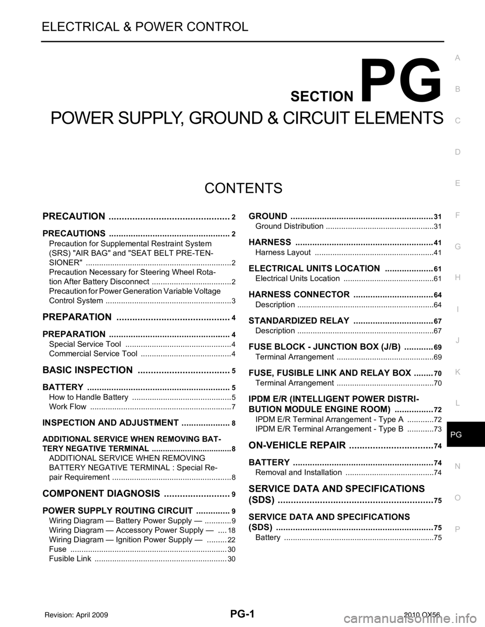
CONTENTS
POWER SUPPLY, GROUND & CIRCUIT ELEMENTS
PRECAUTION .......
........................................2
PRECAUTIONS .............................................. .....2
Precaution for Supplemental Restraint System
(SRS) "AIR BAG" and "SEAT BELT PRE-TEN-
SIONER" ............................................................. ......
2
Precaution Necessary for Steering Wheel Rota-
tion After Battery Disconnect ............................... ......
2
Precaution for Power Generation Variable Voltage
Control System ..........................................................
3
PREPARATION ............................................4
PREPARATION .............................................. .....4
Special Service Tool ........................................... ......4
Commercial Service Tool ..........................................4
BASIC INSPECTION ....................................5
BATTERY ....................................................... .....5
How to Handle Battery ........................................ ......5
Work Flow ........................................................... ......7
INSPECTION AND ADJUSTMENT .....................8
ADDITIONAL SERVICE WHEN REMOVING BAT-
TERY NEGATIVE TERMINAL ............................... ......
8
ADDITIONAL SERVICE WHEN REMOVING
BATTERY NEGATIVE TERMINAL : Special Re-
pair Requirement ................................................. ......
8
COMPONENT DIAGNOSIS ..........................9
POWER SUPPLY ROUTING CIRCUIT .......... .....9
Wiring Diagram — Battery Power Supply — ....... ......9
Wiring Diagram — Accessory Power Supply — .....18
Wiring Diagram — Ignition Power Supply — ..........22
Fuse ........................................................................30
Fusible Link .............................................................30
GROUND ...........................................................31
Ground Distribution .............................................. ....31
HARNESS .........................................................41
Harness Layout ................................................... ....41
ELECTRICAL UNITS LOCATION ....................61
Electrical Units Location ..........................................61
HARNESS CONNECTOR .................................64
Description ...............................................................64
STANDARDIZED RELAY .................................67
Description ...............................................................67
FUSE BLOCK - JUNCTION BOX (J/B) ............69
Terminal Arrangement .............................................69
FUSE, FUSIBLE LINK AND RELAY BOX ........70
Terminal Arrangement .............................................70
IPDM E/R (INTELLIGENT POWER DISTRI-
BUTION MODULE ENGINE ROOM) ................
72
IPDM E/R Terminal Arrangement - Type A .............72
IPDM E/R Terminal Arrangement - Type B .............73
ON-VEHICLE REPAIR .................................74
BATTERY ..........................................................74
Removal and Installation ..................................... ....74
SERVICE DATA AND SPECIFICATIONS
(SDS) ............... .......................................... ...
75
SERVICE DATA AND SPECIFICATIONS
(SDS) .................................................................
75
Battery ................................................................. ....75
Revision: April 20092010 QX56
Page 3291 of 4210

THIRD SEATSE-19
< COMPONENT DIAGNOSIS >
C
DE
F
G H
I
K L
M A
B
SE
N
O P
THIRD SEAT
Power Supply and Ground Circu it Check for Third Row Power Folding Seat Control
Unit
INFOID:0000000005147387
Regarding Wiring Diagram information, refer to SE-24, "Wiring Diagram".
1.CHECK FUSES AND FUSIBLE LINK
Check for blown fuses or fusible link.
Are any fuses or fusible links blown?
YES >> Install new fuse. Eliminate cause of malfunction if fuse blows again.
NO >> GO TO 2
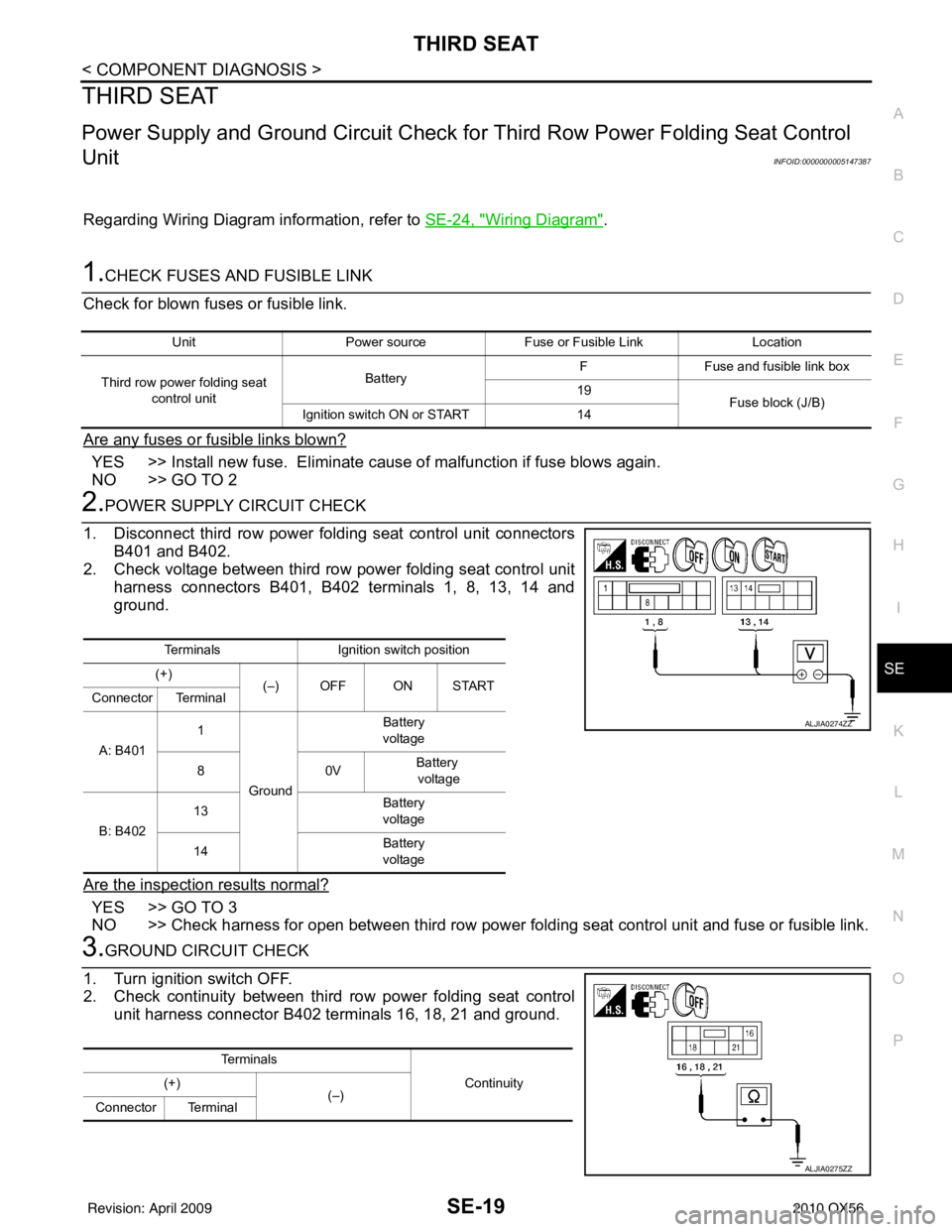
2.POWER SUPPLY CIRCUIT CHECK
1. Disconnect third row power folding seat control unit connectors B401 and B402.
2. Check voltage between third row power folding seat control unit harness connectors B401, B402 terminals 1, 8, 13, 14 and
ground.
Are the inspection results normal?
YES >> GO TO 3
NO >> Check harness for open between third row power folding seat control unit and fuse or fusible link.
3.GROUND CIRCUIT CHECK
1. Turn ignition switch OFF.
2. Check continuity between third row power folding seat control unit harness connector B402 terminals 16, 18, 21 and ground.
Unit Power source Fuse or Fusible Link Location
Third row power folding seat control unit Battery
F
Fuse and fusible link box
19 Fuse block (J/B)
Ignition switch ON or START 14
TerminalsIgnition switch position
(+) (–) OFF ON START
Connector Terminal
A: B401 1
Ground Battery
voltage
80 VBattery
voltage
B: B402 13
Battery
voltage
14 Battery
voltage
ALJIA0274ZZ
Te r m i n a l s
Continuity
(+)
(–)
Connector Terminal
ALJIA0275ZZ
Revision: April 20092010 QX56