Page 1425 of 4210
![INFINITI QX56 2010 Factory Service Manual EC-72
< FUNCTION DIAGNOSIS >[VK56DE]
ON BOARD DIAGNOSTIC (OBD) SYSTEM
*: DTC P1442 and P1456 does not apply to JA60 models but appears in DTC Work Support Mode screens.
Generic Scan Tool (GST) Functio INFINITI QX56 2010 Factory Service Manual EC-72
< FUNCTION DIAGNOSIS >[VK56DE]
ON BOARD DIAGNOSTIC (OBD) SYSTEM
*: DTC P1442 and P1456 does not apply to JA60 models but appears in DTC Work Support Mode screens.
Generic Scan Tool (GST) Functio](/manual-img/42/57032/w960_57032-1424.png)
EC-72
< FUNCTION DIAGNOSIS >[VK56DE]
ON BOARD DIAGNOSTIC (OBD) SYSTEM
*: DTC P1442 and P1456 does not apply to JA60 models but appears in DTC Work Support Mode screens.
Generic Scan Tool (GST) FunctionINFOID:0000000005149080
DESCRIPTION
Generic Scan Tool (OBDII scan tool) complying with SAE J1978 has
8 different functions explained below.
ISO15765-4 is used as the protocol.
The name GST or Generic Scan Tool is used in this service manual.
FUNCTION
Test mode
Test itemCorresponding DTC No. Reference page
EVAPORATIVE
SYSTEM PURG FLOW P0441
P0441EC-213
EVP SML LEAK P0442/P1442* P0442
EC-218P0455EC-254
EVP V/S LEAK P0456/P1456* P0456EC-261
PURG VOL CN/V P1444 P0443EC-225
A/F SEN1 A/F SEN1 (B1) P1276
P0130EC-137A/F SEN1 (B1) P1278/P1279 P0133EC-149
A/F SEN1 (B2) P1286 P0150EC-137
A/F SEN1 (B2) P1288/P1289 P0153EC-149
HO2S2 HO2S2 (B1) P0139
P0139EC-167
HO2S2 (B1) P1146 P0138EC-160
HO2S2 (B1) P1147 P0137EC-155
HO2S2 (B2) P0159 P0159EC-167
HO2S2 (B2) P1166 P0158EC-160
HO2S2 (B2) P1167 P0157EC-155
SEF139P
Diagnostic test mode Function
Service $01 READINESS TESTS This diagnostic service gains access to current emission-related data values, including an-
alog inputs and outputs, digital inputs and outputs, and system status information.
Service $02 (FREEZE DATA) This diagnostic service gains access to emission-related data value which were stored by
ECM during the freeze frame. For details, refer to
EC-459, "
DTC Index".
Service $03 DTCs This diagnostic service gains access to emission-related power train trouble codes which
were stored by ECM.
Service $04 CLEAR DIAG INFO This diagnostic service can clear all emission-related diagnostic information. This in-
cludes:
• Clear number of diagnostic trouble codes (Service $01)
• Clear diagnostic trouble codes (Service $03)
• Clear trouble code for freeze frame data (Service $01)
• Clear freeze frame data (Service $02)
• Reset status of system monitoring test (Service $01)
• Clear on board monitoring test results (Service $06 and $07)
Service $06 (ON BOARD TESTS) This diagnostic service accesses the results of on board diagnostic monitoring tests of
specific components/systems that are not continuously monitored.
Revision: April 20092010 QX56
Page 2918 of 4210
PG-8
< BASIC INSPECTION >
INSPECTION AND ADJUSTMENT
INSPECTION AND ADJUSTMENT
ADDITIONAL SERVICE WHEN REMOVING BATTERY NEGATIVE TERMINAL
ADDITIONAL SERVICE WHEN REMOVING BATTERY NEGATIVE TERMINAL : Spe-
cial Repair Requirement
INFOID:0000000005337686
Required Procedure After Battery Disconnection
System ItemReference
Engine Control Idle Air Volume Learning Refer to EC-18, "
Idle Air Volume
Learning".
Brake Control Steering Angle Sensor Neutral Position Refer to BRC-8
.
Body, Lock & Security Automatic Back Door Initialization Refer to DLK-9, "
ADDITIONAL
SERVICE WHEN REMOVING BAT-
TERY NEGATIVE TERMINAL :
Special Repair Requirement".
Roof Sunroof Memory Reset/Initialization Refer to RF-5
.
Seats Automatic Drive Positioner System Initialization Refer to Owner's Manual.
Audio-Visual System Audio (Radio Preset)
Refer to Owner's Manual.
Navigation System Refer to Owner's Manual.
Rear View Monitor Guiding Line Adjustment Refer to AV- 7
.
Revision: April 20092010 QX56
Page 2984 of 4210
PG-74
< ON-VEHICLE REPAIR >
BATTERY
ON-VEHICLE REPAIR
BATTERY
Removal and InstallationINFOID:0000000005146588
REMOVAL
1. Disconnect the negative battery terminal (1) and positive batteryterminal (2).
CAUTION:
Remove negative battery terminal first.
2. Remove the battery cover.
3. Remove the battery clamp bolt (3) and battery clamp.
4. Remove the battery.
INSTALLATION
Installation is in the reverse order of removal.
CAUTION:
When installing, install the po sitive battery terminal first.
Reset electronic systems as necessary. Refer to PG-8, "
ADDITIONAL SERVICE WHEN REMOVING BAT-
TERY NEGATIVE TERMINAL : Special Repair Requirement".
: Front
AWBIA0504ZZ
Battery clamp bolt : 14.7 N·m (1.5 kg-m, 11 ft-lb)
Battery terminal nut : 3.5 N·m (0.36 kg-m, 31 in-lb)
Revision: April 20092010 QX56
Page 3133 of 4210

INSPECTION AND ADJUSTMENTRF-5
< BASIC INSPECTION >
C
DE
F
G H
I
J
L
M A
B
RF
N
O P
INSPECTION AND ADJUSTMENT
ADDITIONAL SERVICE WHEN REPLACING CONTROL UNIT
ADDITIONAL SERVICE WHEN REPL ACING CONTROL UNIT : Description
INFOID:0000000005147269
MEMORY RESET PROCEDURE
1. Please observe the following instructi ons at confirming the sunroof operation.
NOTE:
Do not disconnect the electronic power while the sunroof is operating or within 5 seconds after the sunroof
stops. (to wipe-out the memory of lid position and operating friction.)
2. Initialization of system should be conducted after the following conditions.
• When the sunroof motor is changed.
• When the sunroof does not operate normally. (Incomplete initialization conditions)
ADDITIONAL SERVICE WHEN REPLACING CONTROL UNIT : Special Repair Re-
quirement
INFOID:0000000005147270
INITIALIZATION PROCEDURE
If the sunroof does not close or open automatically, us e the following procedure to return sunroof operation to
normal.
1. Turn ignition switch ON.
2. Push and hold the sunroof tilt switch in the forw ard (DOWN) position until the sunroof is fully closed.
3. After the sunroof has closed all the way, push and hold the tilt switch forward (DOWN) again for more than 2 seconds to re-learn motor position.
4. Initialization is complete if the sunroof operates normally.
BASIC INSPECTION
BASIC INSPECTION : Special Repair RequirementINFOID:0000000005147271
BASIC INSPECTION
1.INSPECTION START
1. Check the service history.
2. Check the following parts.
• Fuse/circuit breaker blown.
• Poor connection, open or short circuit of harness connector.
• Battery voltage.
Is the inspection result normal?
YES >> Inspection End.
NO >> Repair or replace the malfunctioning parts.
Revision: April 20092010 QX56
Page 3187 of 4210

SUNROOF SYSTEMRF-59
< ON-VEHICLE REPAIR >
C
DE
F
G H
I
J
L
M A
B
RF
N
O P
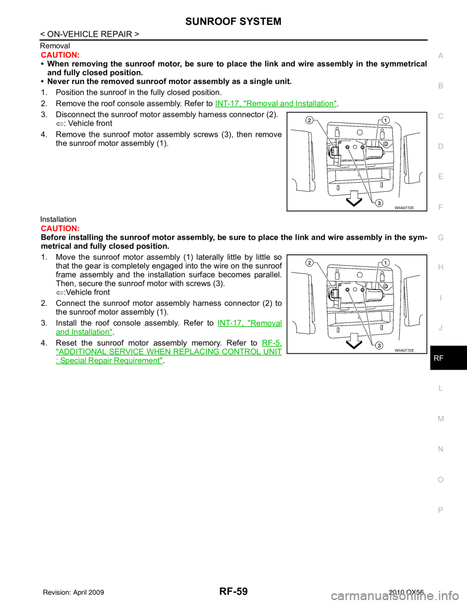
Removal
CAUTION:
• When removing the sunroof motor, be sure to
place the link and wire assembly in the symmetrical
and fully closed position.
• Never run the removed sunroof motor assembly as a single unit.
1. Position the sunroof in the fully closed position.
2. Remove the roof console assembly. Refer to INT-17, "
Removal and Installation".
3. Disconnect the sunroof motor assembly harness connector (2). ⇐: Vehicle front
4. Remove the sunroof motor assembly screws (3), then remove the sunroof motor assembly (1).
Installation
CAUTION:
Before installing the sunroof motor assembly, be sure to place the link and wire assembly in the sym-
metrical and fully closed position.
1. Move the sunroof motor assembly (1) laterally little by little so
that the gear is completely engaged into the wire on the sunroof
frame assembly and the installation surface becomes parallel.
Then, secure the sunroof motor with screws (3).
⇐:Vehicle front
2. Connect the sunroof motor assembly harness connector (2) to the sunroof motor assembly (1).
3. Install the roof console assembly. Refer to INT-17, "
Removal
and Installation".
4. Reset the sunroof motor assembly memory. Refer to RF-5,
"ADDITIONAL SERVICE WHEN REPLACING CONTROL UNIT
: Special Repair Requirement".
WIIA0772E
WIIA0772E
Revision: April 20092010 QX56