2009 SUBARU TRIBECA turbine speed sensor resistance
[x] Cancel search: turbine speed sensor resistancePage 2130 of 2453
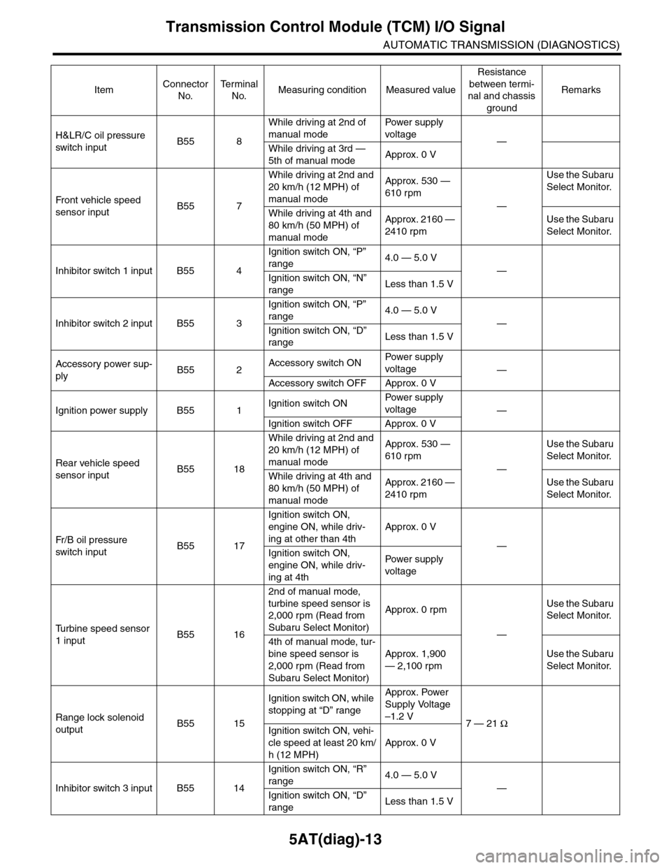
5AT(diag)-13
Transmission Control Module (TCM) I/O Signal
AUTOMATIC TRANSMISSION (DIAGNOSTICS)
H&LR/C oil pressure
switch inputB55 8
While driving at 2nd of
manual mode
Pow er s up p ly
voltage—
While driving at 3rd —
5th of manual modeApprox. 0 V
Fr o nt veh ic l e sp e ed
sensor inputB55 7
While driving at 2nd and
20 km/h (12 MPH) of
manual mode
Approx. 530 —
610 rpm
—
Use the Subaru
Select Monitor.
While driving at 4th and
80 km/h (50 MPH) of
manual mode
Approx. 2160 —
2410 rpm
Use the Subaru
Select Monitor.
Inhibitor switch 1 input B55 4
Ignition switch ON, “P”
range4.0 — 5.0 V
—
Ignition switch ON, “N”
rangeLess than 1.5 V
Inhibitor switch 2 input B55 3
Ignition switch ON, “P”
range4.0 — 5.0 V
—
Ignition switch ON, “D”
rangeLess than 1.5 V
Accessory power sup-
plyB55 2Accessory switch ONPow er s up p ly
voltage—
Accessory switch OFF Approx. 0 V
Ignition power supply B55 1Ignition switch ONPow er s up p ly
voltage—
Ignition switch OFF Approx. 0 V
Rear vehicle speed
sensor inputB55 18
While driving at 2nd and
20 km/h (12 MPH) of
manual mode
Approx. 530 —
610 rpm
—
Use the Subaru
Select Monitor.
While driving at 4th and
80 km/h (50 MPH) of
manual mode
Approx. 2160 —
2410 rpm
Use the Subaru
Select Monitor.
Fr / B oi l p r e ssu r e
switch inputB55 17
Ignition switch ON,
engine ON, while driv-
ing at other than 4th
Approx. 0 V
—
Ignition switch ON,
engine ON, while driv-
ing at 4th
Pow er s up p ly
voltage
Tu r b i n e s p e e d s e n s o r
1 inputB55 16
2nd of manual mode,
turbine speed sensor is
2,000 rpm (Read from
Subaru Select Monitor)
Approx. 0 rpm
—
Use the Subaru
Select Monitor.
4th of manual mode, tur-
bine speed sensor is
2,000 rpm (Read from
Subaru Select Monitor)
Approx. 1,900
— 2,100 rpm
Use the Subaru
Select Monitor.
Range lock solenoid
outputB55 15
Ignition switch ON, while
stopping at “D” range
Approx. Power
Supply Voltage
–1.2 V7 — 21 Ω
Ignition switch ON, vehi-
cle speed at least 20 km/
h (12 MPH)
Approx. 0 V
Inhibitor switch 3 input B55 14
Ignition switch ON, “R”
range4.0 — 5.0 V
—
Ignition switch ON, “D”
rangeLess than 1.5 V
ItemConnector
No.
Te r m i n a l
No.Measuring condition Measured value
Resistance
between termi-
nal and chassis
ground
Remarks
Page 2131 of 2453
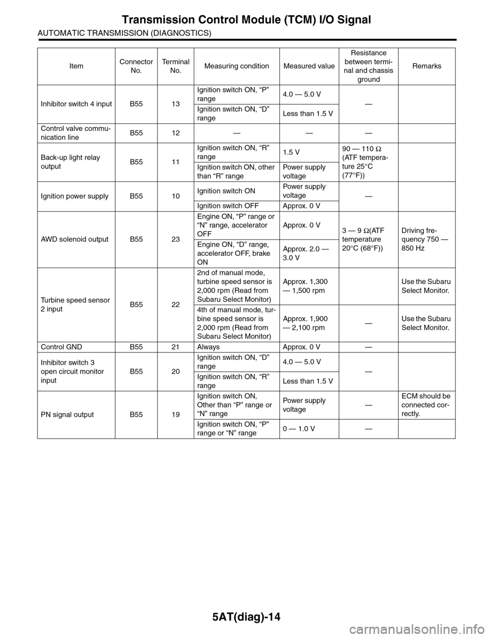
5AT(diag)-14
Transmission Control Module (TCM) I/O Signal
AUTOMATIC TRANSMISSION (DIAGNOSTICS)
Inhibitor switch 4 input B55 13
Ignition switch ON, “P”
range4.0 — 5.0 V
—
Ignition switch ON, “D”
rangeLess than 1.5 V
Control valve commu-
nication lineB55 12 — — —
Back-up light relay
outputB55 11
Ignition switch ON, “R”
range1.5 V90 — 110 Ω
(ATF tempera-
ture 25°C
(77°F))
Ignition switch ON, other
than “R” range
Pow er s up p ly
voltage
Ignition power supply B55 10Ignition switch ONPow er s up p ly
voltage—
Ignition switch OFF Approx. 0 V
AW D s o le n oi d o u tp u t B 5 5 2 3
Engine ON, “P” range or
“N” range, accelerator
OFF
Approx. 0 V3 — 9 Ω(ATF
temperature
20°C (68°F))
Driving fre-
quency 750 —
850 HzEngine ON, “D” range,
accelerator OFF, brake
ON
Approx. 2.0 —
3.0 V
Tu r b i n e s p e e d s e n s o r
2 inputB55 22
2nd of manual mode,
turbine speed sensor is
2,000 rpm (Read from
Subaru Select Monitor)
Approx. 1,300
— 1,500 rpm
Use the Subaru
Select Monitor.
4th of manual mode, tur-
bine speed sensor is
2,000 rpm (Read from
Subaru Select Monitor)
Approx. 1,900
— 2,100 rpm—Use the Subaru
Select Monitor.
Control GND B55 21 Always Approx. 0 V —
Inhibitor switch 3
open circuit monitor
input
B55 20
Ignition switch ON, “D”
range4.0 — 5.0 V
—
Ignition switch ON, “R”
rangeLess than 1.5 V
PN signal output B55 19
Ignition switch ON,
Other than “P” range or
“N” range
Pow er s up p ly
voltage—
ECM should be
connected cor-
rectly.
Ignition switch ON, “P”
range or “N” range0 — 1.0 V —
ItemConnector
No.
Te r m i n a l
No.Measuring condition Measured value
Resistance
between termi-
nal and chassis
ground
Remarks
Page 2159 of 2453
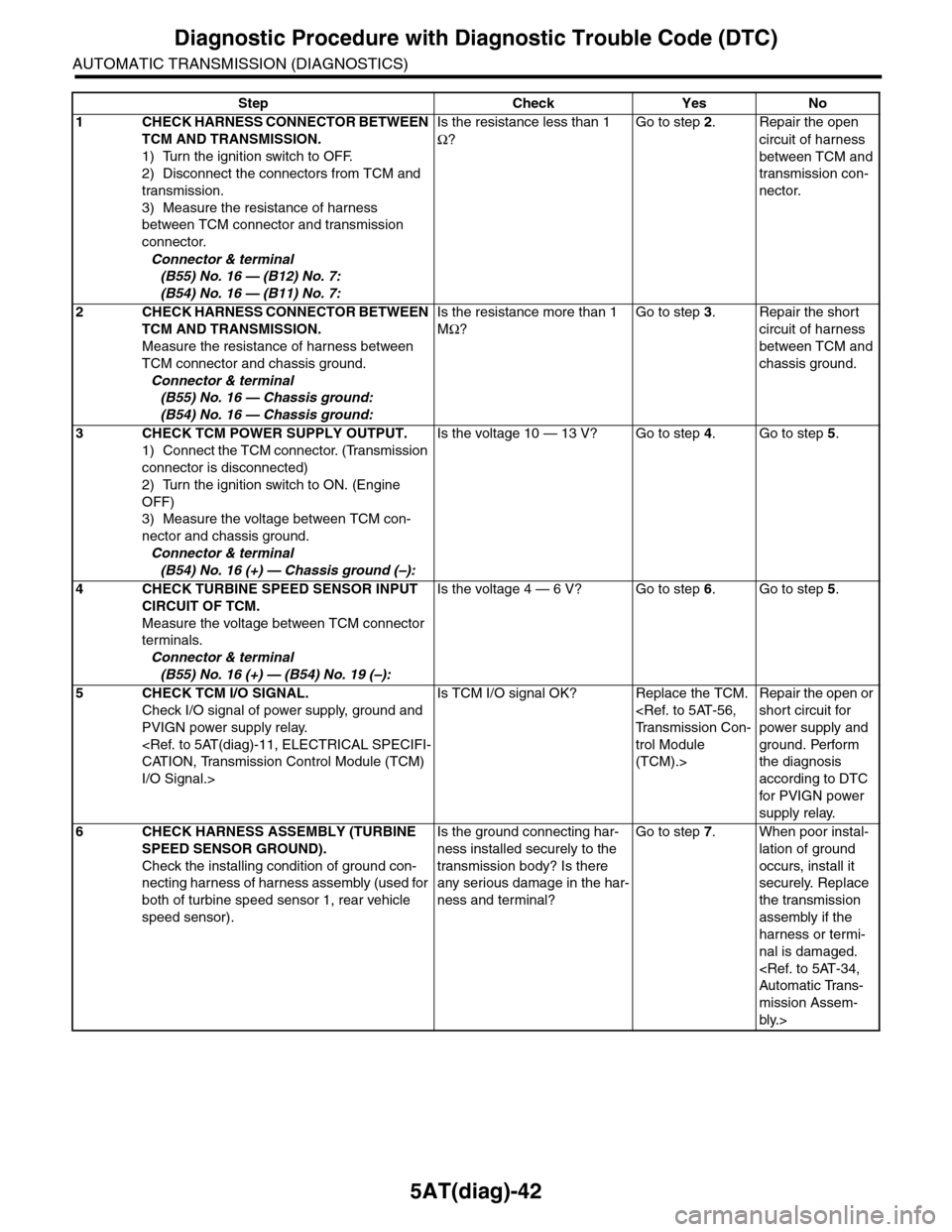
5AT(diag)-42
Diagnostic Procedure with Diagnostic Trouble Code (DTC)
AUTOMATIC TRANSMISSION (DIAGNOSTICS)
Step Check Yes No
1CHECK HARNESS CONNECTOR BETWEEN
TCM AND TRANSMISSION.
1) Turn the ignition switch to OFF.
2) Disconnect the connectors from TCM and
transmission.
3) Measure the resistance of harness
between TCM connector and transmission
connector.
Connector & terminal
(B55) No. 16 — (B12) No. 7:
(B54) No. 16 — (B11) No. 7:
Is the resistance less than 1
Ω?
Go to step 2.Repair the open
circuit of harness
between TCM and
transmission con-
nector.
2CHECK HARNESS CONNECTOR BETWEEN
TCM AND TRANSMISSION.
Measure the resistance of harness between
TCM connector and chassis ground.
Connector & terminal
(B55) No. 16 — Chassis ground:
(B54) No. 16 — Chassis ground:
Is the resistance more than 1
MΩ?
Go to step 3.Repair the short
circuit of harness
between TCM and
chassis ground.
3CHECK TCM POWER SUPPLY OUTPUT.
1) Connect the TCM connector. (Transmission
connector is disconnected)
2) Turn the ignition switch to ON. (Engine
OFF)
3) Measure the voltage between TCM con-
nector and chassis ground.
Connector & terminal
(B54) No. 16 (+) — Chassis ground (–):
Is the voltage 10 — 13 V? Go to step 4.Go to step 5.
4CHECK TURBINE SPEED SENSOR INPUT
CIRCUIT OF TCM.
Measure the voltage between TCM connector
terminals.
Connector & terminal
(B55) No. 16 (+) — (B54) No. 19 (–):
Is the voltage 4 — 6 V? Go to step 6.Go to step 5.
5CHECK TCM I/O SIGNAL.
Check I/O signal of power supply, ground and
PVIGN power supply relay.
I/O Signal.>
Is TCM I/O signal OK? Replace the TCM.
trol Module
(TCM).>
Repair the open or
short circuit for
power supply and
ground. Perform
the diagnosis
according to DTC
for PVIGN power
supply relay.
6CHECK HARNESS ASSEMBLY (TURBINE
SPEED SENSOR GROUND).
Check the installing condition of ground con-
necting harness of harness assembly (used for
both of turbine speed sensor 1, rear vehicle
speed sensor).
Is the ground connecting har-
ness installed securely to the
transmission body? Is there
any serious damage in the har-
ness and terminal?
Go to step 7.When poor instal-
lation of ground
occurs, install it
securely. Replace
the transmission
assembly if the
harness or termi-
nal is damaged.
mission Assem-
bly.>
Page 2160 of 2453
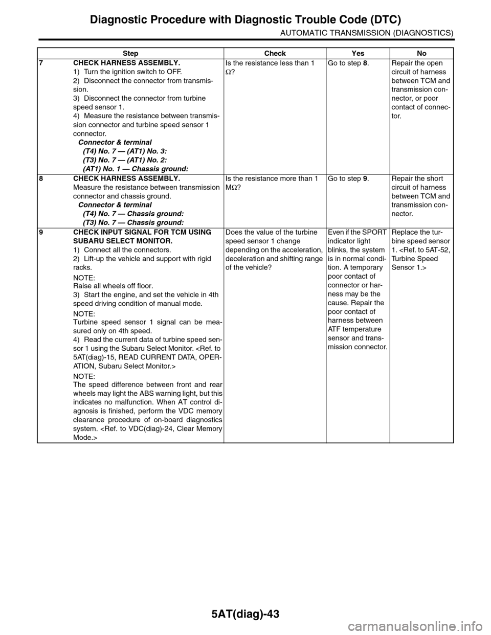
5AT(diag)-43
Diagnostic Procedure with Diagnostic Trouble Code (DTC)
AUTOMATIC TRANSMISSION (DIAGNOSTICS)
7CHECK HARNESS ASSEMBLY.
1) Turn the ignition switch to OFF.
2) Disconnect the connector from transmis-
sion.
3) Disconnect the connector from turbine
speed sensor 1.
4) Measure the resistance between transmis-
sion connector and turbine speed sensor 1
connector.
Connector & terminal
(T4) No. 7 — (AT1) No. 3:
(T3) No. 7 — (AT1) No. 2:
(AT1) No. 1 — Chassis ground:
Is the resistance less than 1
Ω?
Go to step 8.Repair the open
circuit of harness
between TCM and
transmission con-
nector, or poor
contact of connec-
tor.
8CHECK HARNESS ASSEMBLY.
Measure the resistance between transmission
connector and chassis ground.
Connector & terminal
(T4) No. 7 — Chassis ground:
(T3) No. 7 — Chassis ground:
Is the resistance more than 1
MΩ?
Go to step 9.Repair the short
circuit of harness
between TCM and
transmission con-
nector.
9CHECK INPUT SIGNAL FOR TCM USING
SUBARU SELECT MONITOR.
1) Connect all the connectors.
2) Lift-up the vehicle and support with rigid
racks.
NOTE:Raise all wheels off floor.
3) Start the engine, and set the vehicle in 4th
speed driving condition of manual mode.
NOTE:Turbine speed sensor 1 signal can be mea-
sured only on 4th speed.
4) Read the current data of turbine speed sen-
sor 1 using the Subaru Select Monitor.
AT I O N , S u b a r u S e l e c t M o n i t o r . >
NOTE:The speed difference between front and rear
wheels may light the ABS warning light, but this
indicates no malfunction. When AT control di-
agnosis is finished, perform the VDC memory
clearance procedure of on-board diagnostics
system.
Does the value of the turbine
speed sensor 1 change
depending on the acceleration,
deceleration and shifting range
of the vehicle?
Even if the SPORT
indicator light
blinks, the system
is in normal condi-
tion. A temporary
poor contact of
connector or har-
ness may be the
cause. Repair the
poor contact of
harness between
AT F t e m p e r a t u r e
sensor and trans-
mission connector.
Replace the tur-
bine speed sensor
1.
Sensor 1.>
Step Check Yes No
Page 2164 of 2453
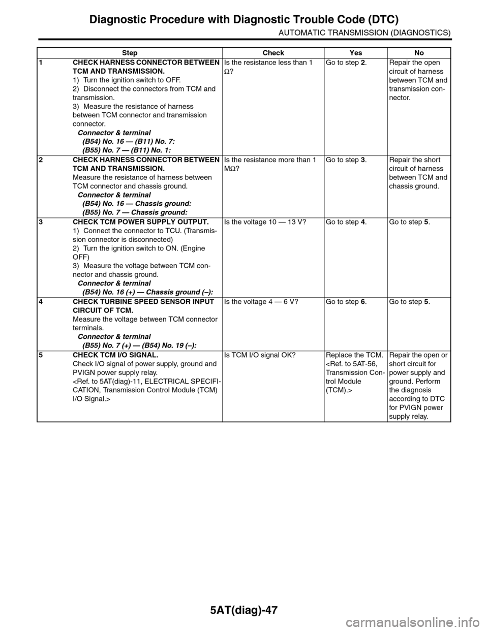
5AT(diag)-47
Diagnostic Procedure with Diagnostic Trouble Code (DTC)
AUTOMATIC TRANSMISSION (DIAGNOSTICS)
Step Check Yes No
1CHECK HARNESS CONNECTOR BETWEEN
TCM AND TRANSMISSION.
1) Turn the ignition switch to OFF.
2) Disconnect the connectors from TCM and
transmission.
3) Measure the resistance of harness
between TCM connector and transmission
connector.
Connector & terminal
(B54) No. 16 — (B11) No. 7:
(B55) No. 7 — (B11) No. 1:
Is the resistance less than 1
Ω?
Go to step 2.Repair the open
circuit of harness
between TCM and
transmission con-
nector.
2CHECK HARNESS CONNECTOR BETWEEN
TCM AND TRANSMISSION.
Measure the resistance of harness between
TCM connector and chassis ground.
Connector & terminal
(B54) No. 16 — Chassis ground:
(B55) No. 7 — Chassis ground:
Is the resistance more than 1
MΩ?
Go to step 3.Repair the short
circuit of harness
between TCM and
chassis ground.
3CHECK TCM POWER SUPPLY OUTPUT.
1) Connect the connector to TCU. (Transmis-
sion connector is disconnected)
2) Turn the ignition switch to ON. (Engine
OFF)
3) Measure the voltage between TCM con-
nector and chassis ground.
Connector & terminal
(B54) No. 16 (+) — Chassis ground (–):
Is the voltage 10 — 13 V? Go to step 4.Go to step 5.
4CHECK TURBINE SPEED SENSOR INPUT
CIRCUIT OF TCM.
Measure the voltage between TCM connector
terminals.
Connector & terminal
(B55) No. 7 (+) — (B54) No. 19 (–):
Is the voltage 4 — 6 V? Go to step 6.Go to step 5.
5CHECK TCM I/O SIGNAL.
Check I/O signal of power supply, ground and
PVIGN power supply relay.
I/O Signal.>
Is TCM I/O signal OK? Replace the TCM.
trol Module
(TCM).>
Repair the open or
short circuit for
power supply and
ground. Perform
the diagnosis
according to DTC
for PVIGN power
supply relay.
Page 2219 of 2453
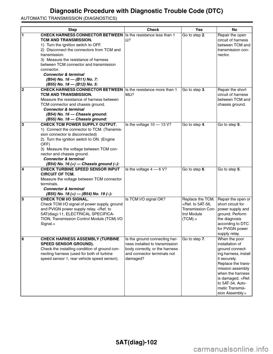
5AT(diag)-102
Diagnostic Procedure with Diagnostic Trouble Code (DTC)
AUTOMATIC TRANSMISSION (DIAGNOSTICS)
Step Check Yes No
1CHECK HARNESS CONNECTOR BETWEEN
TCM AND TRANSMISSION.
1) Turn the ignition switch to OFF.
2) Disconnect the connectors from TCM and
transmission.
3) Measure the resistance of harness
between TCM connector and transmission
connector.
Connector & terminal
(B54) No. 16 — (B11) No. 7:
(B55) No. 18 — (B12) No. 5:
Is the resistance less than 1
Ω?
Go to step 2.Repair the open
circuit of harness
between TCM and
transmission con-
nector.
2CHECK HARNESS CONNECTOR BETWEEN
TCM AND TRANSMISSION.
Measure the resistance of harness between
TCM connector and chassis ground.
Connector & terminal
(B54) No. 16 — Chassis ground:
(B55) No. 18 — Chassis ground:
Is the resistance more than 1
MΩ?
Go to step 3.Repair the short
circuit of harness
between TCM and
chassis ground.
3CHECK TCM POWER SUPPLY OUTPUT.
1) Connect the connector to TCM. (Transmis-
sion connector is disconnected)
2) Turn the ignition switch to ON. (Engine
OFF)
3) Measure the voltage between TCM con-
nector and chassis ground.
Connector & terminal
(B54) No. 16 (+) — Chassis ground (–):
Is the voltage 10 — 13 V? Go to step 4.Go to step 5.
4CHECK TURBINE SPEED SENSOR INPUT
CIRCUIT OF TCM.
Measure the voltage between TCM connector
terminals.
Connector & terminal
(B55) No. 18 (+) — (B54) No. 19 (–):
Is the voltage 4 — 6 V? Go to step 6.Go to step 5.
5CHECK TCM I/O SIGNAL.
Check TCM I/O signal of power supply, ground
and PVIGN power supply relay.
TION, Transmission Control Module (TCM) I/O
Signal.>
Is TCM I/O signal OK? Replace the TCM.
trol Module
(TCM).>
Repair the open or
short circuit for
power supply and
ground. Perform
the diagnosis
according to DTC
for PVIGN power
supply relay.
6CHECK HARNESS ASSEMBLY (TURBINE
SPEED SENSOR GROUND).
Check the installing condition of ground con-
necting harness (used for both of turbine
speed sensor 1, rear vehicle speed sensor).
Is the ground connecting har-
ness installed to transmission
body correctly, or the harness
and connector terminals not
damaged?
Go to step 7.When the poor
installation of
ground connect-
ing harness, install
it securely.
Replace the trans-
mission assembly
when the harness
is damaged.
matic Transmis-
sion Assembly.>
Page 2225 of 2453
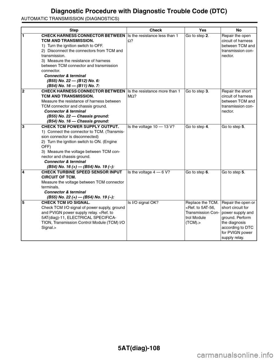
5AT(diag)-108
Diagnostic Procedure with Diagnostic Trouble Code (DTC)
AUTOMATIC TRANSMISSION (DIAGNOSTICS)
Step Check Yes No
1CHECK HARNESS CONNECTOR BETWEEN
TCM AND TRANSMISSION.
1) Turn the ignition switch to OFF.
2) Disconnect the connectors from TCM and
transmission.
3) Measure the resistance of harness
between TCM connector and transmission
connector.
Connector & terminal
(B55) No. 22 — (B12) No. 6:
(B54) No. 16 — (B11) No. 7:
Is the resistance less than 1
Ω?
Go to step 2.Repair the open
circuit of harness
between TCM and
transmission con-
nector.
2CHECK HARNESS CONNECTOR BETWEEN
TCM AND TRANSMISSION.
Measure the resistance of harness between
TCM connector and chassis ground.
Connector & terminal
(B55) No. 22 — Chassis ground:
(B54) No. 16 — Chassis ground:
Is the resistance more than 1
MΩ?
Go to step 3.Repair the short
circuit of harness
between TCM and
transmission con-
nector.
3CHECK TCM POWER SUPPLY OUTPUT.
1) Connect the connector to TCM. (Transmis-
sion connector is disconnected)
2) Turn the ignition switch to ON. (Engine
OFF)
3) Measure the voltage between TCM con-
nector and chassis ground.
Connector & terminal
(B54) No. 16 (+) — (B54) No. 19 (–):
Is the voltage 10 — 13 V? Go to step 4.Go to step 5.
4CHECK TURBINE SPEED SENSOR INPUT
CIRCUIT OF TCM.
Measure the voltage between TCM connector
terminals.
Connector & terminal
(B55) No. 22 (+) — (B54) No. 19 (–):
Is the voltage 4 — 6 V? Go to step 6.Go to step 5.
5CHECK TCM I/O SIGNAL.
Check TCM I/O signal of power supply, ground
and PVIGN power supply relay.
TION, Transmission Control Module (TCM) I/O
Signal.>
Is I/O signal OK? Replace the TCM.
trol Module
(TCM).>
Repair the open or
short circuit for
power supply and
ground. Perform
the diagnosis
according to DTC
for PVIGN power
supply relay.
Page 2226 of 2453
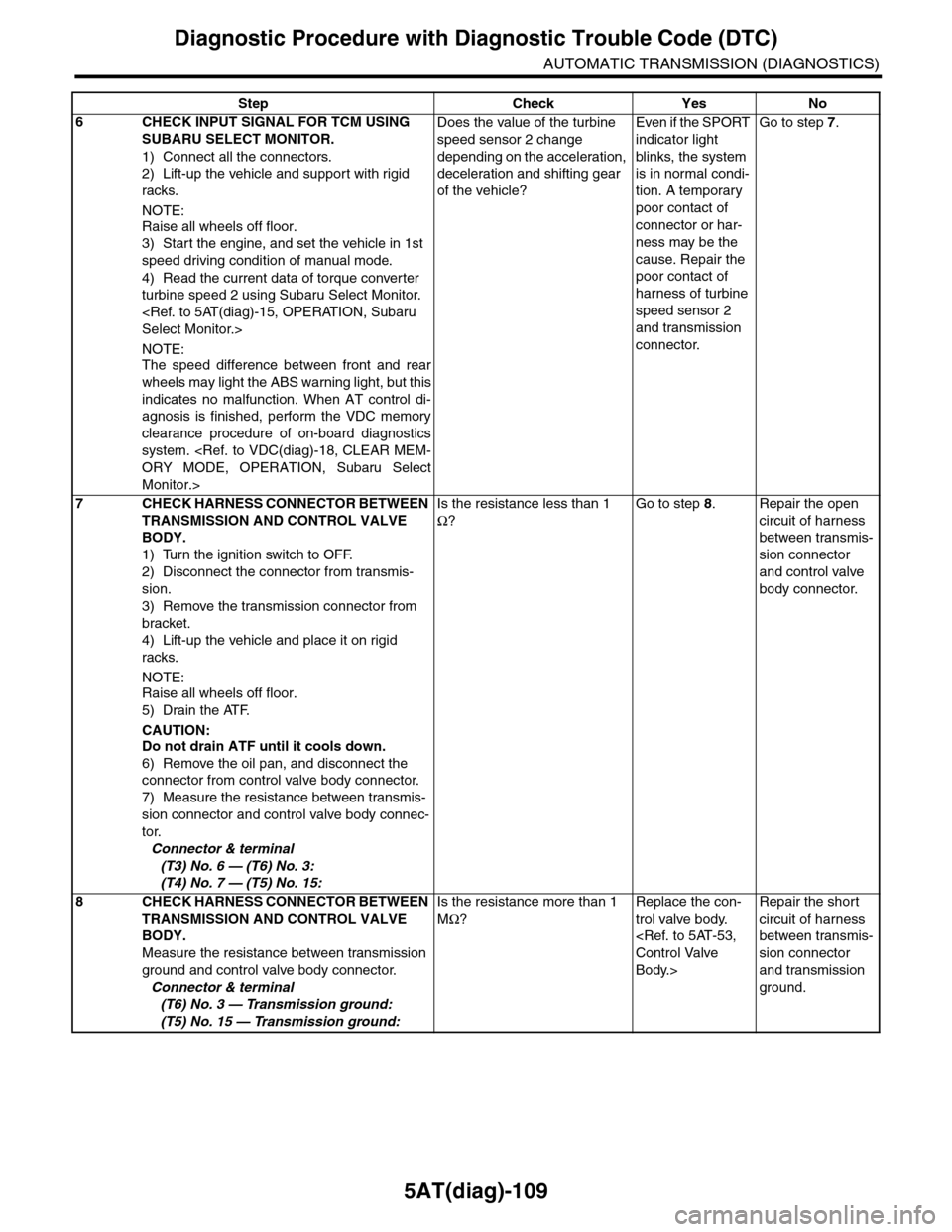
5AT(diag)-109
Diagnostic Procedure with Diagnostic Trouble Code (DTC)
AUTOMATIC TRANSMISSION (DIAGNOSTICS)
6CHECK INPUT SIGNAL FOR TCM USING
SUBARU SELECT MONITOR.
1) Connect all the connectors.
2) Lift-up the vehicle and support with rigid
racks.
NOTE:
Raise all wheels off floor.
3) Start the engine, and set the vehicle in 1st
speed driving condition of manual mode.
4) Read the current data of torque converter
turbine speed 2 using Subaru Select Monitor.
NOTE:The speed difference between front and rear
wheels may light the ABS warning light, but this
indicates no malfunction. When AT control di-
agnosis is finished, perform the VDC memory
clearance procedure of on-board diagnostics
system.
Monitor.>
Does the value of the turbine
speed sensor 2 change
depending on the acceleration,
deceleration and shifting gear
of the vehicle?
Even if the SPORT
indicator light
blinks, the system
is in normal condi-
tion. A temporary
poor contact of
connector or har-
ness may be the
cause. Repair the
poor contact of
harness of turbine
speed sensor 2
and transmission
connector.
Go to step 7.
7CHECK HARNESS CONNECTOR BETWEEN
TRANSMISSION AND CONTROL VALVE
BODY.
1) Turn the ignition switch to OFF.
2) Disconnect the connector from transmis-
sion.
3) Remove the transmission connector from
bracket.
4) Lift-up the vehicle and place it on rigid
racks.
NOTE:
Raise all wheels off floor.
5) Drain the ATF.
CAUTION:Do not drain ATF until it cools down.
6) Remove the oil pan, and disconnect the
connector from control valve body connector.
7) Measure the resistance between transmis-
sion connector and control valve body connec-
tor.
Connector & terminal
(T3) No. 6 — (T6) No. 3:
(T4) No. 7 — (T5) No. 15:
Is the resistance less than 1
Ω?
Go to step 8.Repair the open
circuit of harness
between transmis-
sion connector
and control valve
body connector.
8CHECK HARNESS CONNECTOR BETWEEN
TRANSMISSION AND CONTROL VALVE
BODY.
Measure the resistance between transmission
ground and control valve body connector.
Connector & terminal
(T6) No. 3 — Transmission ground:
(T5) No. 15 — Transmission ground:
Is the resistance more than 1
MΩ?
Replace the con-
trol valve body.
Body.>
Repair the short
circuit of harness
between transmis-
sion connector
and transmission
ground.
Step Check Yes No