Page 2072 of 2453
5AT-56
Transmission Control Module (TCM)
AUTOMATIC TRANSMISSION
19.Transmission Control Mod-
ule (TCM)
A: REMOVAL
1) Disconnect the ground cable from battery.
2) Remove the lower cover and then disconnect
the connector.
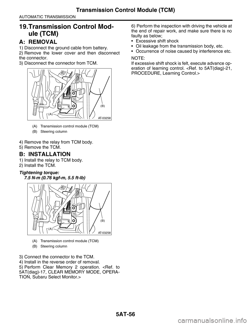
3) Disconnect the connector from TCM.
4) Remove the relay from TCM body.
5) Remove the TCM.
B: INSTALLATION
1) Install the relay to TCM body.
2) Install the TCM.
Tightening torque:
7.5 N·m (0.76 kgf-m, 5.5 ft-lb)
3) Connect the connector to the TCM.
4) Install in the reverse order of removal.
5) Perform Clear Memory 2 operation.
5AT(diag)-17, CLEAR MEMORY MODE, OPERA-
TION, Subaru Select Monitor.>
6) Perform the inspection with driving the vehicle at
the end of repair work, and make sure there is no
faulty as below;
•Excessive shift shock
•Oil leakage from the transmission body, etc.
•Occurrence of noise caused by interference etc.
NOTE:
If excessive shift shock is felt, execute advance op-
eration of learning control.
PROCEDURE, Learning Control.>
(A) Transmission control module (TCM)
(B) Steering column
(A) Transmission control module (TCM)
(B) Steering column
AT-03258(A)
(B)
AT-03258(A)
(B)
Page 2084 of 2453
5AT-68
Reduction Driven Gear
AUTOMATIC TRANSMISSION
27.Reduction Driven Gear
A: REMOVAL
1) Remove the transmission assembly from vehicle
body.
Transmission Assembly.>
2) Remove the rear wheel speed sensor, and sep-
arate the extension case from transmission case.
3) Remove the center differential carrier.
5AT-71, REMOVAL, Center Differential Carrier.>
4) Set the range select lever to the “P” range.
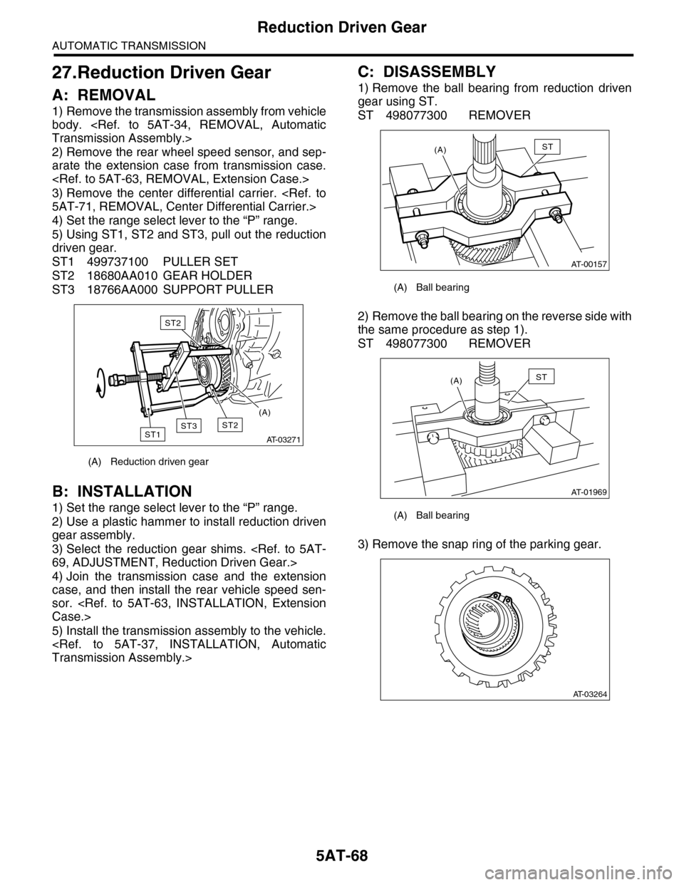
5) Using ST1, ST2 and ST3, pull out the reduction
driven gear.
ST1 499737100 PULLER SET
ST2 18680AA010 GEAR HOLDER
ST3 18766AA000 SUPPORT PULLER
B: INSTALLATION
1) Set the range select lever to the “P” range.
2) Use a plastic hammer to install reduction driven
gear assembly.
3) Select the reduction gear shims.
69, ADJUSTMENT, Reduction Driven Gear.>
4) Join the transmission case and the extension
case, and then install the rear vehicle speed sen-
sor.
Case.>
5) Install the transmission assembly to the vehicle.
Transmission Assembly.>
C: DISASSEMBLY
1) Remove the ball bearing from reduction driven
gear using ST.
ST 498077300 REMOVER
2) Remove the ball bearing on the reverse side with
the same procedure as step 1).
ST 498077300 REMOVER
3) Remove the snap ring of the parking gear.
(A) Reduction driven gear
AT-03271
ST2ST1
ST2
ST3
(A)
(A) Ball bearing
(A) Ball bearing
AT-00157
(A)ST
AT-01969
(A)ST
AT-03264
Page 2085 of 2453
5AT-69
Reduction Driven Gear
AUTOMATIC TRANSMISSION
4) Using the ST, remove the parking gear.
ST 18767AA000 REMOVER
D: ASSEMBLY
1) Using the ST, install the parking gear.
ST 499755602 PRESS
2) Install the snap ring.
3) Install the new ball bearing to reduction driven
gear using press.
ST 18654AA000 INSTALLER
4) Install the ball bearing on the reverse side with
the same procedure as step 3).
ST 18654AA000 INSTALLER
E: INSPECTION
Make sure the ball bearing and gear is not de-
formed or damaged.
F: ADJUSTMENT
1) Using the ST, measure the height “A” from the
AT main case mating surface to ball bearing outer
ring contact surface.
ST 499575400 GAUGE
2) Using the ST, measure the depth “B”, which is
from mating surface of extension case to ball bear-
ing outer ring contact surface.
ST 499575400 GAUGE
(A) Ball bearing 1
AT-03265
ST
ST
AT-03264
AT-03267
ST
AT-03268
ST
AT-03269
ST
A
AT-03270
ST
B
Page 2100 of 2453
5AT-84
Drive Pinion Shaft Assembly
AUTOMATIC TRANSMISSION
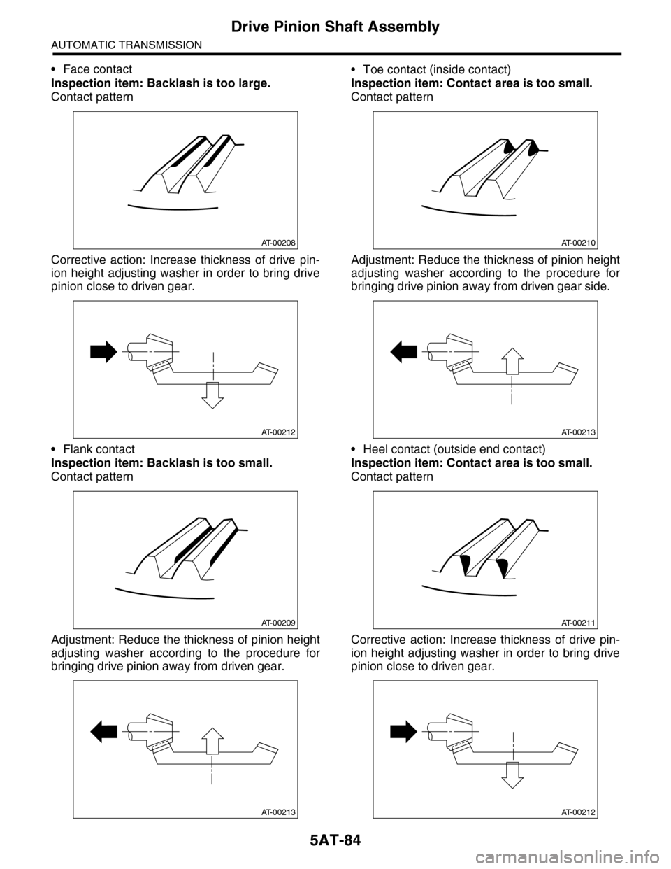
•Face contact
Inspection item: Backlash is too large.
Contact pattern
Corrective action: Increase thickness of drive pin-
ion height adjusting washer in order to bring drive
pinion close to driven gear.
•Flank contact
Inspection item: Backlash is too small.
Contact pattern
Adjustment: Reduce the thickness of pinion height
adjusting washer according to the procedure for
bringing drive pinion away from driven gear.
•Toe contact (inside contact)
Inspection item: Contact area is too small.
Contact pattern
Adjustment: Reduce the thickness of pinion height
adjusting washer according to the procedure for
bringing drive pinion away from driven gear side.
•Heel contact (outside end contact)
Inspection item: Contact area is too small.
Contact pattern
Corrective action: Increase thickness of drive pin-
ion height adjusting washer in order to bring drive
pinion close to driven gear.
AT-00208
AT-00212
AT-00209
AT-00213
AT-00210
AT-00213
AT-00211
AT-00212
Page 2113 of 2453
5AT-97
AT Main Case
AUTOMATIC TRANSMISSION
24) Install the extension case.
STALLATION, Extension Case.>
25) Install the control valve body.
INSTALLATION, Control Valve Body.>
26) Install the converter case assembly to the
transmission case assembly.
STALLATION, Converter Case.>
27) Install the air breather hose.
INSTALLATION, Air Breather Hose.>
28) Install the ATF filter pipe.
STALLATION, ATF Cooler Pipe & Hose.>
29) Install the oil charge pipe together with an O-
ring.
Pipe.>
30) Install the torque converter assembly.
5AT-62, INSTALLATION, Torque Converter As-
sembly.>
31) Install the transmission assembly to the vehi-
cle.
Transmission Assembly.>
32) Perform Clear Memory 2 operation.
5AT(diag)-17, CLEAR MEMORY MODE, OPERA-
TION, Subaru Select Monitor.>
33) Perform the inspection with driving the vehicle
at the end of repair work, and make sure there is no
faulty as below;
•Excessive shift shock
•Oil leakage from the transmission body, etc.
•Occurrence of noise caused by interference etc.
NOTE:
If excessive shift shock is felt, execute advance op-
eration of learning control.
PROCEDURE, Learning Control.>
C: DISASSEMBLY
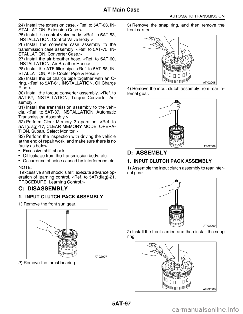
1. INPUT CLUTCH PACK ASSEMBLY
1) Remove the front sun gear.
2) Remove the thrust bearing.
3) Remove the snap ring, and then remove the
front carrier.
4) Remove the input clutch assembly from rear in-
ternal gear.
D: ASSEMBLY
1. INPUT CLUTCH PACK ASSEMBLY
1) Assemble the input clutch assembly to rear inter-
nal gear.
2) Install the front carrier, and then install the snap
ring.
AT-02007
AT-02008
AT-02009
AT-02009
AT-02008
Page 2119 of 2453
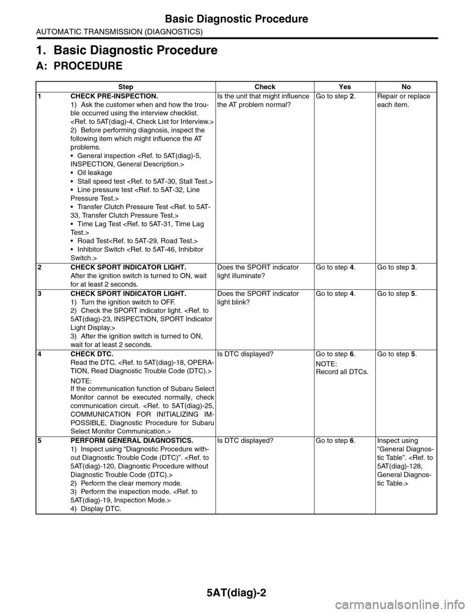
5AT(diag)-2
Basic Diagnostic Procedure
AUTOMATIC TRANSMISSION (DIAGNOSTICS)
1. Basic Diagnostic Procedure
A: PROCEDURE
Step Check Yes No
1CHECK PRE-INSPECTION.
1) Ask the customer when and how the trou-
ble occurred using the interview checklist.
2) Before performing diagnosis, inspect the
following item which might influence the AT
problems.
•General inspection
INSPECTION, General Description.>
•Oil leakage
•Stall speed test
•Line pressure test
Pressure Test.>
•Transfer Clutch Pressure Test
33, Transfer Clutch Pressure Test.>
•Time Lag Test
Te s t . >
•Road Test
•Inhibitor Switch
Switch.>
Is the unit that might influence
the AT problem normal?
Go to step 2.Repair or replace
each item.
2CHECK SPORT INDICATOR LIGHT.
After the ignition switch is turned to ON, wait
for at least 2 seconds.
Does the SPORT indicator
light illuminate?
Go to step 4.Go to step 3.
3CHECK SPORT INDICATOR LIGHT.
1) Turn the ignition switch to OFF.
2) Check the SPORT indicator light.
5AT(diag)-23, INSPECTION, SPORT Indicator
Light Display.>
3) After the ignition switch is turned to ON,
wait for at least 2 seconds.
Does the SPORT indicator
light blink?
Go to step 4.Go to step 5.
4CHECK DTC.
Read the DTC.
TION, Read Diagnostic Trouble Code (DTC).>
NOTE:If the communication function of Subaru Select
Monitor cannot be executed normally, check
communication circuit.
COMMUNICATION FOR INITIALIZING IM-
POSSIBLE, Diagnostic Procedure for Subaru
Select Monitor Communication.>
Is DTC displayed? Go to step 6.
NOTE:
Record all DTCs.
Go to step 5.
5PERFORM GENERAL DIAGNOSTICS.
1) Inspect using “Diagnostic Procedure with-
out Diagnostic Trouble Code (DTC)”.
5AT(diag)-120, Diagnostic Procedure without
Diagnostic Trouble Code (DTC).>
2) Perform the clear memory mode.
3) Perform the inspection mode.
5AT(diag)-19, Inspection Mode.>
4) Display DTC.
Is DTC displayed? Go to step 6.Inspect using
“General Diagnos-
tic Table”.
5AT(diag)-128,
General Diagnos-
tic Table.>
Page 2120 of 2453
5AT(diag)-3
Basic Diagnostic Procedure
AUTOMATIC TRANSMISSION (DIAGNOSTICS)
6PERFORM THE DIAGNOSIS.
1) Inspect using the “Diagnostic Procedure
with Diagnostic Trouble Code (DTC)”.
5AT(diag)-31, Diagnostic Procedure with Diag-
nostic Trouble Code (DTC).>
NOTE:
For DTC table, refer to “List of Diagnostic Trou-
ble Code (DTC).”
Diagnostic Trouble Code (DTC).>
2) Repair the trouble cause.
3) Perform the clear memory mode.
4) Perform the inspection mode.
5AT(diag)-19, Inspection Mode.>
5) Display DTC.
Is DTC displayed? Inspect using the
“Diagnostic Proce-
dure with Diagnos-
tic Trouble Code
(DTC)”.
5AT(diag)-31,
Diagnostic Proce-
dure with Diagnos-
tic Trouble Code
(DTC).>
Inspect using
“General Diagnos-
tic Table”.
5AT(diag)-128,
General Diagnos-
tic Table.>
Step Check Yes No
Page 2132 of 2453
5AT(diag)-15
Subaru Select Monitor
AUTOMATIC TRANSMISSION (DIAGNOSTICS)
6. Subaru Select Monitor
A: OPERATION
1. READ DIAGNOSTIC TROUBLE CODE
(DTC)
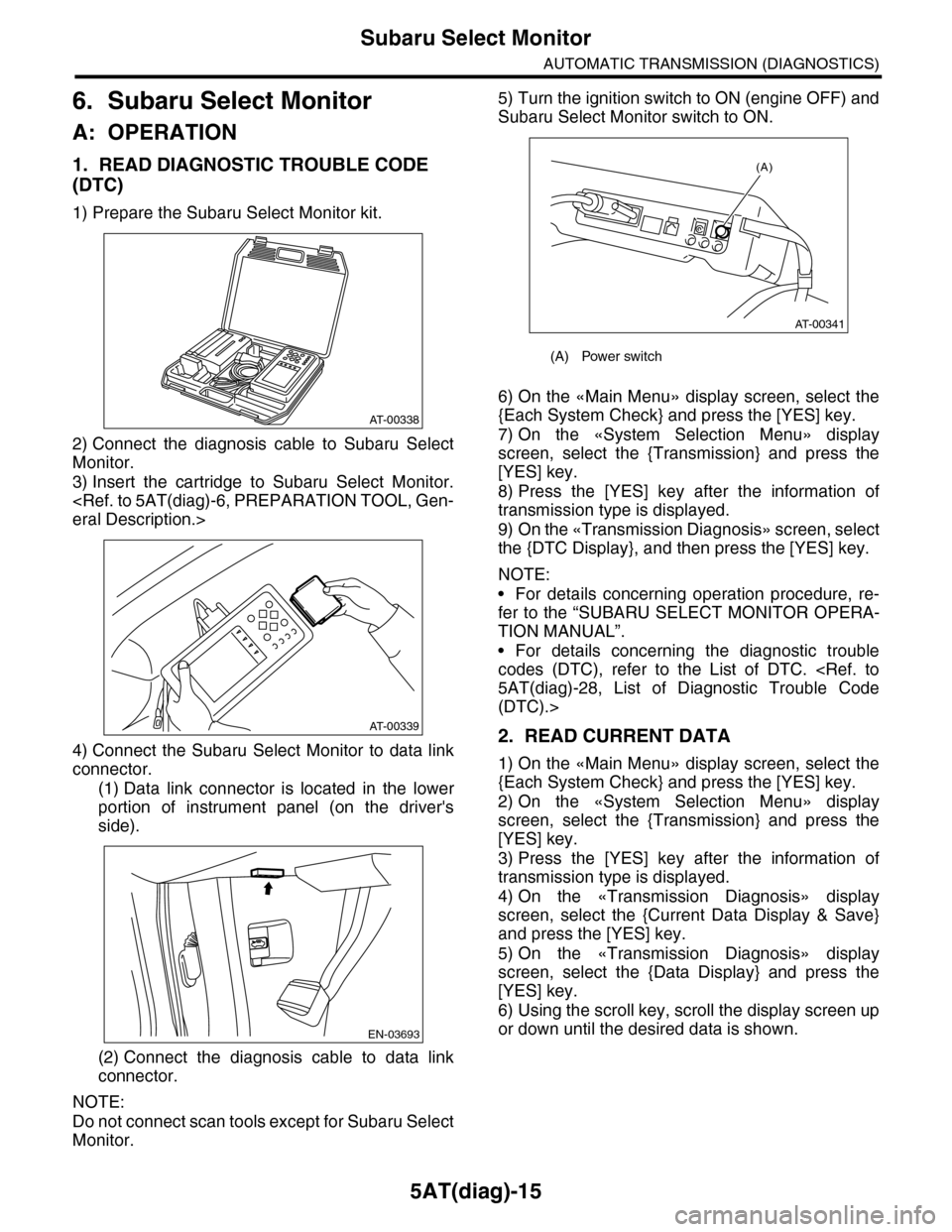
1) Prepare the Subaru Select Monitor kit.
2) Connect the diagnosis cable to Subaru Select
Monitor.
3) Insert the cartridge to Subaru Select Monitor.
eral Description.>
4) Connect the Subaru Select Monitor to data link
connector.
(1) Data link connector is located in the lower
portion of instrument panel (on the driver's
side).
(2) Connect the diagnosis cable to data link
connector.
NOTE:
Do not connect scan tools except for Subaru Select
Monitor.
5) Turn the ignition switch to ON (engine OFF) and
Subaru Select Monitor switch to ON.
6) On the «Main Menu» display screen, select the
{Each System Check} and press the [YES] key.
7) On the «System Selection Menu» display
screen, select the {Transmission} and press the
[YES] key.
8) Press the [YES] key after the information of
transmission type is displayed.
9) On the «Transmission Diagnosis» screen, select
the {DTC Display}, and then press the [YES] key.
NOTE:
•For details concerning operation procedure, re-
fer to the “SUBARU SELECT MONITOR OPERA-
TION MANUAL”.
•For details concerning the diagnostic trouble
codes (DTC), refer to the List of DTC.
5AT(diag)-28, List of Diagnostic Trouble Code
(DTC).>
2. READ CURRENT DATA
1) On the «Main Menu» display screen, select the
{Each System Check} and press the [YES] key.
2) On the «System Selection Menu» display
screen, select the {Transmission} and press the
[YES] key.
3) Press the [YES] key after the information of
transmission type is displayed.
4) On the «Transmission Diagnosis» display
screen, select the {Current Data Display & Save}
and press the [YES] key.
5) On the «Transmission Diagnosis» display
screen, select the {Data Display} and press the
[YES] key.
6) Using the scroll key, scroll the display screen up
or down until the desired data is shown.
AT-00338
AT-00339
EN-03693
(A) Power switch
(A)
AT-00341