2009 SUBARU TRIBECA ac 25 procedure
[x] Cancel search: ac 25 procedurePage 2133 of 2453
5AT(diag)-16
Subaru Select Monitor
AUTOMATIC TRANSMISSION (DIAGNOSTICS)
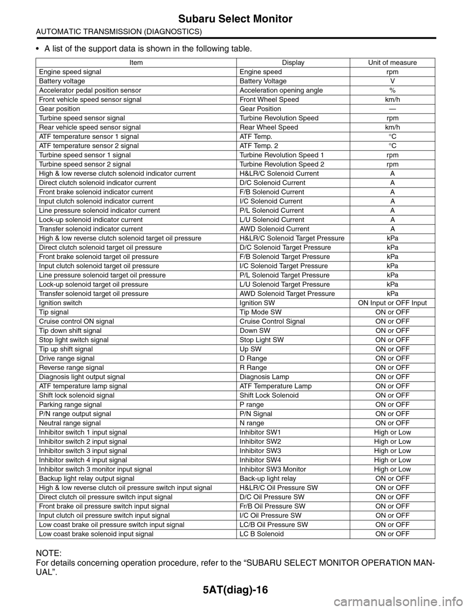
•A list of the support data is shown in the following table.
NOTE:
For details concerning operation procedure, refer to the “SUBARU SELECT MONITOR OPERATION MAN-
UAL”.
Item Display Unit of measure
Engine speed signal Engine speed rpm
Battery voltage Battery Voltage V
Accelerator pedal position sensor Acceleration opening angle %
Fr o nt veh ic l e sp e ed se n so r s ig n al Fr o n t W h ee l S p e ed km/ h
Gear position Gear Position —
Tu r b i n e s p e e d s e n s o r s i g n a l Tu r b i n e R e v o l u t i o n S p e e d r p m
Rear vehicle speed sensor signal Rear Wheel Speed km/h
ATF temperature sensor 1 signal ATF Temp. °C
ATF temperature sensor 2 signal ATF Temp. 2 °C
Tu r b i n e s p e e d s e n s o r 1 s i g n a l Tu r b i n e R e v o l u t i o n S p e e d 1 r p m
Tu r b i n e s p e e d s e n s o r 2 s i g n a l Tu r b i n e R e v o l u t i o n S p e e d 2 r p m
High & low reverse clutch solenoid indicator current H&LR/C Solenoid Current A
Direct clutch solenoid indicator current D/C Solenoid Current A
Fr o nt b rake so l en oi d in di c at o r c u rr e n t F / B S o l en o id Cur r e nt A
Input clutch solenoid indicator current I/C Solenoid Current A
Line pressure solenoid indicator current P/L Solenoid Current A
Lock-up solenoid indicator current L/U Solenoid Current A
Tr a n s f e r s o l e n o i d i n d i c a t o r c u r r e n t A W D S o l e n o i d C u r r e n t A
High & low reverse clutch solenoid target oil pressure H&LR/C Solenoid Target Pressure kPa
Direct clutch solenoid target oil pressure D/C Solenoid Target Pressure kPa
Fr o nt b rake so l en oi d ta r g et o il pr e ss ur e F / B S o l en o id Ta r g et P r es su r e kPa
Input clutch solenoid target oil pressure I/C Solenoid Target Pressure kPa
Line pressure solenoid target oil pressure P/L Solenoid Target Pressure kPa
Lock-up solenoid target oil pressure L/U Solenoid Target Pressure kPa
Tr a n s f e r s o l e n o i d t a r g e t o i l p r e s s u r e A W D S o l e n o i d Ta r g e t P r e s s u r e k P a
Ignition switch Ignition SW ON Input or OFF Input
Tip signal Tip Mode SW ON or OFF
Cruise control ON signal Cruise Control Signal ON or OFF
Tip down shift signal Down SW ON or OFF
Stop light switch signal Stop Light SW ON or OFF
Tip up shift signal Up SW ON or OFF
Drive range signal D Range ON or OFF
Reverse range signal R Range ON or OFF
Diagnosis light output signal Diagnosis Lamp ON or OFF
AT F t e m p e r a t u r e l a m p s i g n a l AT F Te m p e r a t u r e L a m p O N o r O F F
Shift lock solenoid signal Shift Lock Solenoid ON or OFF
Par king range signal P range ON or OFF
P/N range output signal P/N Signal ON or OFF
Neutral range signal N range ON or OFF
Inhibitor switch 1 input signal Inhibitor SW1 High or Low
Inhibitor switch 2 input signal Inhibitor SW2 High or Low
Inhibitor switch 3 input signal Inhibitor SW3 High or Low
Inhibitor switch 4 input signal Inhibitor SW4 High or Low
Inhibitor switch 3 monitor input signal Inhibitor SW3 Monitor High or Low
Backup light relay output signal Back-up light relay ON or OFF
High & low reverse clutch oil pressure switch input signal H&LR/C Oil Pressure SW ON or OFF
Direct clutch oil pressure switch input signal D/C Oil Pressure SW ON or OFF
Fr o nt b rake oi l pr e ss ur e swi tc h i n pu t si gn a l Fr / B Oi l P r e ss ur e S W ON or OF F
Input clutch oil pressure switch input signal I/C Oil Pressure SW ON or OFF
Low coast brake oil pressure switch input signal LC/B Oil Pressure SW ON or OFF
Low coast brake solenoid input signal LC B Solenoid ON or OFF
Page 2134 of 2453
5AT(diag)-17
Subaru Select Monitor
AUTOMATIC TRANSMISSION (DIAGNOSTICS)
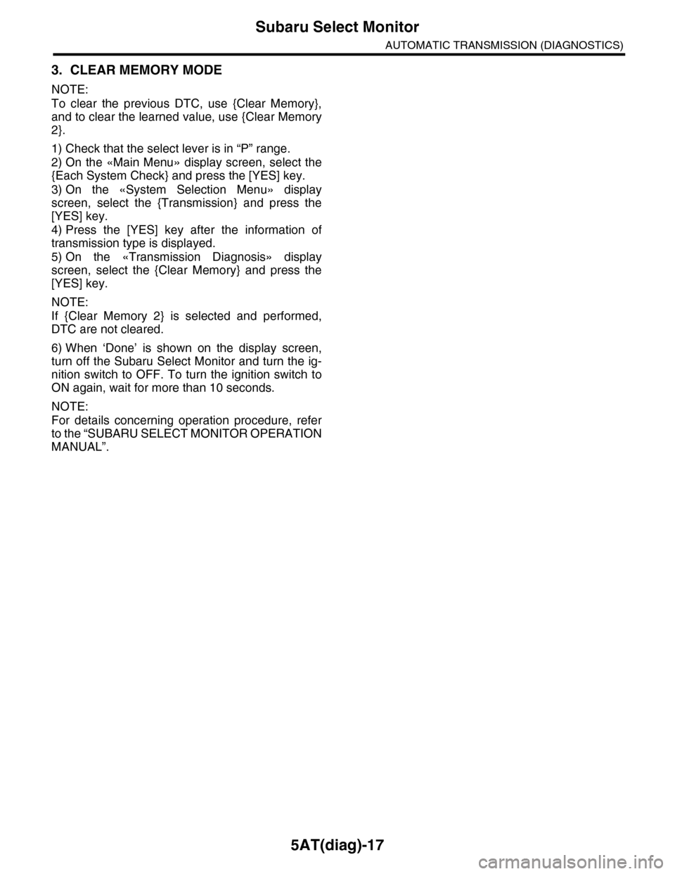
3. CLEAR MEMORY MODE
NOTE:
To clear the previous DTC, use {Clear Memory},
and to clear the learned value, use {Clear Memory
2}.
1) Check that the select lever is in “P” range.
2) On the «Main Menu» display screen, select the
{Each System Check} and press the [YES] key.
3) On the «System Selection Menu» display
screen, select the {Transmission} and press the
[YES] key.
4) Press the [YES] key after the information of
transmission type is displayed.
5) On the «Transmission Diagnosis» display
screen, select the {Clear Memory} and press the
[YES] key.
NOTE:
If {Clear Memory 2} is selected and performed,
DTC are not cleared.
6) When ‘Done’ is shown on the display screen,
turn off the Subaru Select Monitor and turn the ig-
nition switch to OFF. To turn the ignition switch to
ON again, wait for more than 10 seconds.
NOTE:
For details concerning operation procedure, refer
to the “SUBARU SELECT MONITOR OPERATION
MANUAL”.
Page 2136 of 2453
5AT(diag)-19
Inspection Mode
AUTOMATIC TRANSMISSION (DIAGNOSTICS)
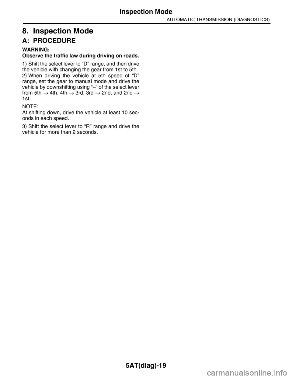
8. Inspection Mode
A: PROCEDURE
WARNING:
Observe the traffic law during driving on roads.
1) Shift the select lever to “D” range, and then drive
the vehicle with changing the gear from 1st to 5th.
2) When driving the vehicle at 5th speed of “D”
range, set the gear to manual mode and drive the
vehicle by downshifting using “–” of the select lever
from 5th → 4th, 4th → 3rd, 3rd → 2nd, and 2nd →
1st.
NOTE:
At shifting down, drive the vehicle at least 10 sec-
onds in each speed.
3) Shift the select lever to “R” range and drive the
vehicle for more than 2 seconds.
Page 2138 of 2453
5AT(diag)-21
Learning Control
AUTOMATIC TRANSMISSION (DIAGNOSTICS)
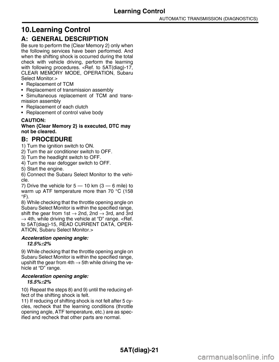
10.Learning Control
A: GENERAL DESCRIPTION
Be sure to perform the {Clear Memory 2} only when
the following services have been performed. And
when the shifting shock is occurred during the total
check with vehicle driving, perform the learning
with following procedures.
Select Monitor.>
•Replacement of TCM
•Replacement of transmission assembly
•Simultaneous replacement of TCM and trans-
mission assembly
•Replacement of each clutch
•Replacement of control valve body
CAUTION:
When {Clear Memory 2} is executed, DTC may
not be cleared.
B: PROCEDURE
1) Turn the ignition switch to ON.
2) Turn the air conditioner switch to OFF.
3) Turn the headlight switch to OFF.
4) Turn the rear defogger switch to OFF.
5) Start the engine.
6) Connect the Subaru Select Monitor to the vehi-
cle.
7) Drive the vehicle for 5 — 10 km (3 — 6 mile) to
warm up ATF temperature more than 70 °C (158
°F).
8) While checking that the throttle opening angle on
Subaru Select Monitor is within the specified range,
shift the gear from 1st → 2nd, 2nd → 3rd, and 3rd
→ 4th, while driving the vehicle at “D” range.
ATION, Subaru Select Monitor.>
Acceleration opening angle:
12.5%±2%
9) While checking that the throttle opening angle on
Subaru Select Monitor is within the specified range,
upshift the gear from 4th → 5 t h w h i l e d r i v i n g t h e v e -
hicle at “D” range.
Acceleration opening angle:
15.5%±2%
10) Repeat the steps 8) and 9) until the reducing ef-
fect of the shifting shock is felt.
11) If reducing of shifting shock is not felt after 5 cy-
cles, recheck that the learning conditions (throttle
opening angle, ATF temperature, etc.) are as spec-
ified and recheck that other parts are normal.
Page 2141 of 2453
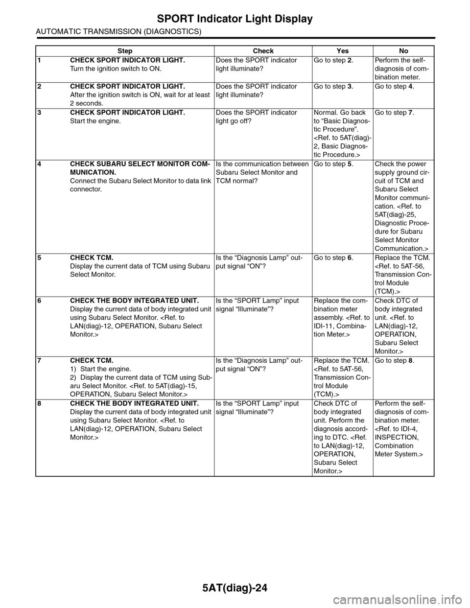
5AT(diag)-24
SPORT Indicator Light Display
AUTOMATIC TRANSMISSION (DIAGNOSTICS)
Step Check Yes No
1CHECK SPORT INDICATOR LIGHT.
Tu r n t h e i g n i t i o n s w i t c h t o O N .
Does the SPORT indicator
light illuminate?
Go to step 2.Perform the self-
diagnosis of com-
bination meter.
2CHECK SPORT INDICATOR LIGHT.
After the ignition switch is ON, wait for at least
2 seconds.
Does the SPORT indicator
light illuminate?
Go to step 3.Go to step 4.
3CHECK SPORT INDICATOR LIGHT.
Start the engine.
Does the SPORT indicator
light go off?
Normal. Go back
to “Basic Diagnos-
tic Procedure”.
tic Procedure.>
Go to step 7.
4CHECK SUBARU SELECT MONITOR COM-
MUNICATION.
Connect the Subaru Select Monitor to data link
connector.
Is the communication between
Subaru Select Monitor and
TCM normal?
Go to step 5.Check the power
supply ground cir-
cuit of TCM and
Subaru Select
Monitor communi-
cation.
Diagnostic Proce-
dure for Subaru
Select Monitor
Communication.>
5CHECK TCM.
Display the current data of TCM using Subaru
Select Monitor.
Is the “Diagnosis Lamp” out-
put signal “ON”?
Go to step 6.Replace the TCM.
trol Module
(TCM).>
6CHECK THE BODY INTEGRATED UNIT.
Display the current data of body integrated unit
using Subaru Select Monitor.
Monitor.>
Is the “SPORT Lamp” input
signal “Illuminate”?
Replace the com-
bination meter
assembly.
tion Meter.>
Check DTC of
body integrated
unit.
OPERATION,
Subaru Select
Monitor.>
7CHECK TCM.
1) Start the engine.
2) Display the current data of TCM using Sub-
aru Select Monitor.
Is the “Diagnosis Lamp” out-
put signal “ON”?
Replace the TCM.
trol Module
(TCM).>
Go to step 8.
8CHECK THE BODY INTEGRATED UNIT.
Display the current data of body integrated unit
using Subaru Select Monitor.
Monitor.>
Is the “SPORT Lamp” input
signal “Illuminate”?
Check DTC of
body integrated
unit. Perform the
diagnosis accord-
ing to DTC.
OPERATION,
Subaru Select
Monitor.>
Per fo r m th e se lf -
diagnosis of com-
bination meter.
Combination
Meter System.>
Page 2142 of 2453
5AT(diag)-25
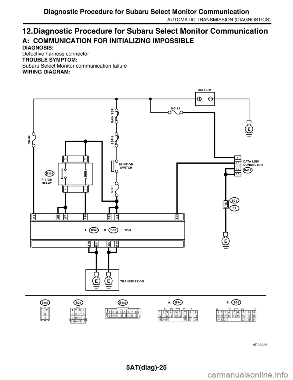
Diagnostic Procedure for Subaru Select Monitor Communication
AUTOMATIC TRANSMISSION (DIAGNOSTICS)
12.Diagnostic Procedure for Subaru Select Monitor Communication
A: COMMUNICATION FOR INITIALIZING IMPOSSIBLE
DIAGNOSIS:
Defective harness connector
TROUBLE SYMPTOM:
Subaru Select Monitor communication failure
WIRING DIAGRAM:
AT-03285
B21
12345678910111213 14 15 16
B54A:
12789563410 11 1219 20 2113 14 15 16 17 18222324
B55B:
12341011 121920 21135614 1578916 17 1822 23 24
IGNITIONSWITCH
P-VIGNRELAY
BATTERY
DATA LINKCONNECTOR
TRANSMISSION
B54A:B55
B357
B: TCM
B402
E
NO.5
NO.32SBF-6 MAIN SBF
A1
A19B21
B1B10A20
A5A14
1
12
10
13
NO.13
B21
E216
E
EE
A7A8A10
32
41
B402
123 8910413 14 15 165671112
B357
34
12
Page 2143 of 2453
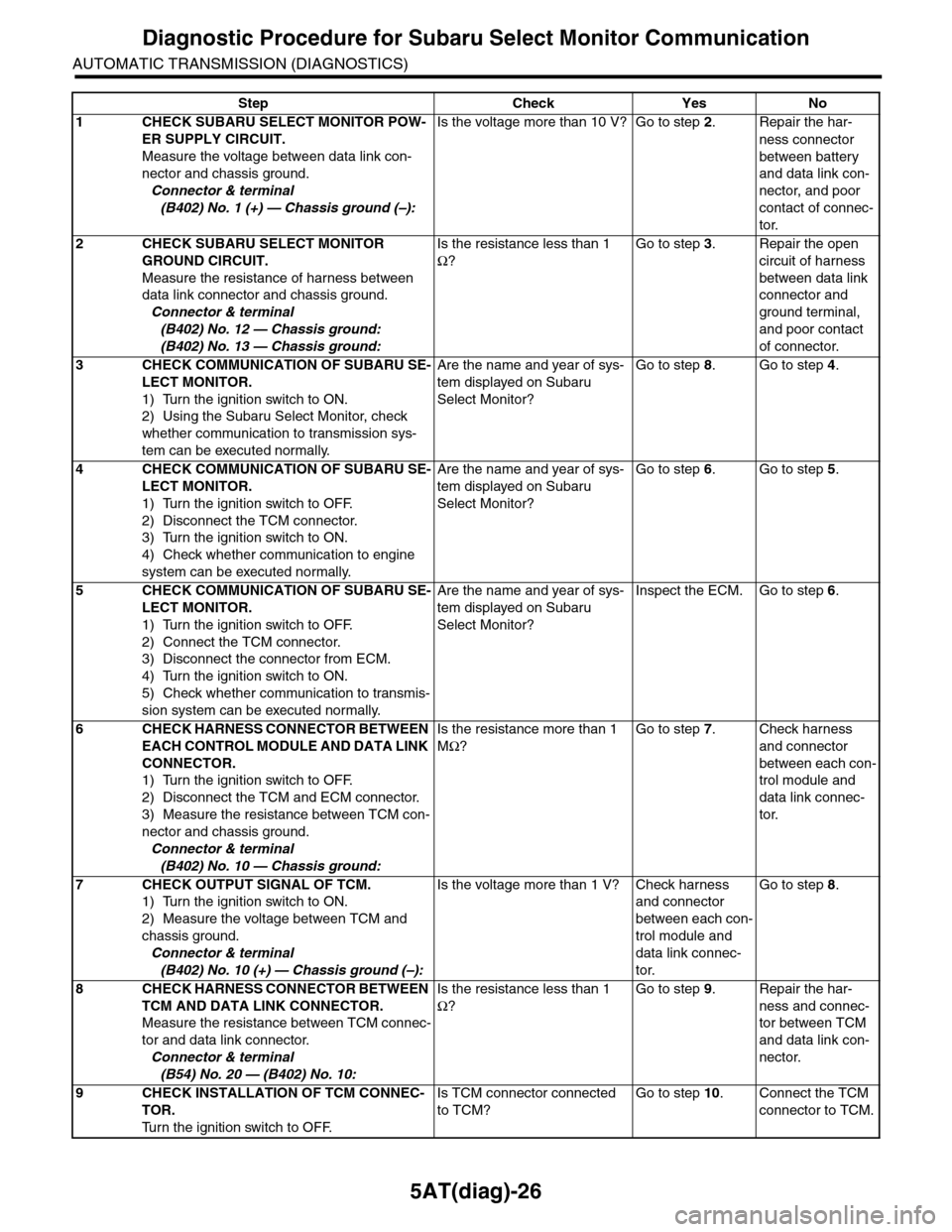
5AT(diag)-26
Diagnostic Procedure for Subaru Select Monitor Communication
AUTOMATIC TRANSMISSION (DIAGNOSTICS)
Step Check Yes No
1CHECK SUBARU SELECT MONITOR POW-
ER SUPPLY CIRCUIT.
Measure the voltage between data link con-
nector and chassis ground.
Connector & terminal
(B402) No. 1 (+) — Chassis ground (–):
Is the voltage more than 10 V? Go to step 2.Repair the har-
ness connector
between battery
and data link con-
nector, and poor
contact of connec-
tor.
2CHECK SUBARU SELECT MONITOR
GROUND CIRCUIT.
Measure the resistance of harness between
data link connector and chassis ground.
Connector & terminal
(B402) No. 12 — Chassis ground:
(B402) No. 13 — Chassis ground:
Is the resistance less than 1
Ω?
Go to step 3.Repair the open
circuit of harness
between data link
connector and
ground terminal,
and poor contact
of connector.
3CHECK COMMUNICATION OF SUBARU SE-
LECT MONITOR.
1) Turn the ignition switch to ON.
2) Using the Subaru Select Monitor, check
whether communication to transmission sys-
tem can be executed normally.
Are the name and year of sys-
tem displayed on Subaru
Select Monitor?
Go to step 8.Go to step 4.
4CHECK COMMUNICATION OF SUBARU SE-
LECT MONITOR.
1) Turn the ignition switch to OFF.
2) Disconnect the TCM connector.
3) Turn the ignition switch to ON.
4) Check whether communication to engine
system can be executed normally.
Are the name and year of sys-
tem displayed on Subaru
Select Monitor?
Go to step 6.Go to step 5.
5CHECK COMMUNICATION OF SUBARU SE-
LECT MONITOR.
1) Turn the ignition switch to OFF.
2) Connect the TCM connector.
3) Disconnect the connector from ECM.
4) Turn the ignition switch to ON.
5) Check whether communication to transmis-
sion system can be executed normally.
Are the name and year of sys-
tem displayed on Subaru
Select Monitor?
Inspect the ECM. Go to step 6.
6CHECK HARNESS CONNECTOR BETWEEN
EACH CONTROL MODULE AND DATA LINK
CONNECTOR.
1) Turn the ignition switch to OFF.
2) Disconnect the TCM and ECM connector.
3) Measure the resistance between TCM con-
nector and chassis ground.
Connector & terminal
(B402) No. 10 — Chassis ground:
Is the resistance more than 1
MΩ?
Go to step 7.Check harness
and connector
between each con-
trol module and
data link connec-
tor.
7CHECK OUTPUT SIGNAL OF TCM.
1) Turn the ignition switch to ON.
2) Measure the voltage between TCM and
chassis ground.
Connector & terminal
(B402) No. 10 (+) — Chassis ground (–):
Is the voltage more than 1 V? Check harness
and connector
between each con-
trol module and
data link connec-
tor.
Go to step 8.
8CHECK HARNESS CONNECTOR BETWEEN
TCM AND DATA LINK CONNECTOR.
Measure the resistance between TCM connec-
tor and data link connector.
Connector & terminal
(B54) No. 20 — (B402) No. 10:
Is the resistance less than 1
Ω?
Go to step 9.Repair the har-
ness and connec-
tor between TCM
and data link con-
nector.
9CHECK INSTALLATION OF TCM CONNEC-
TOR.
Tu r n t h e i g n i t i o n s w i t c h t o O F F.
Is TCM connector connected
to TCM?
Go to step 10.Connect the TCM
connector to TCM.
Page 2144 of 2453
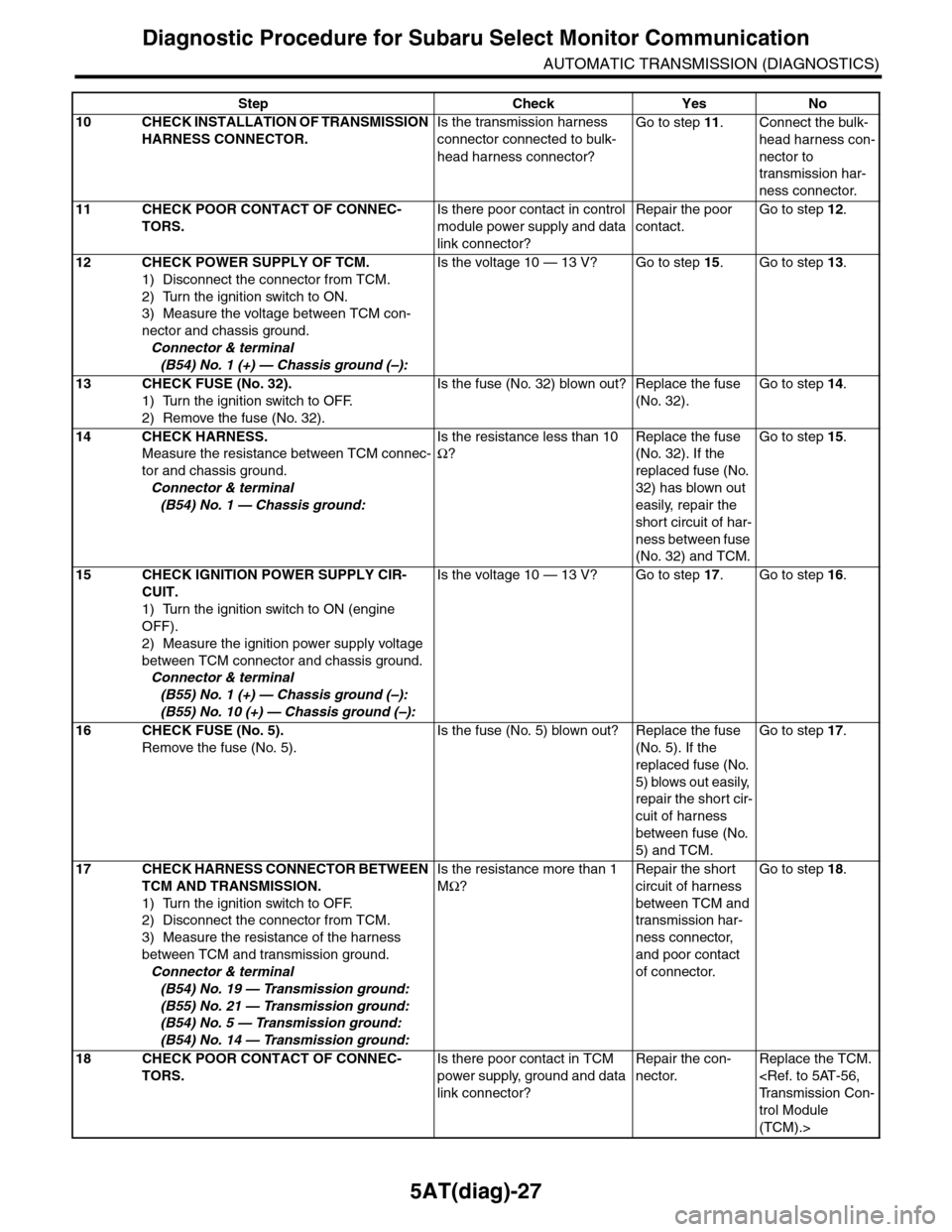
5AT(diag)-27
Diagnostic Procedure for Subaru Select Monitor Communication
AUTOMATIC TRANSMISSION (DIAGNOSTICS)
10 CHECK INSTALLATION OF TRANSMISSION
HARNESS CONNECTOR.
Is the transmission harness
connector connected to bulk-
head harness connector?
Go to step 11.Connect the bulk-
head harness con-
nector to
transmission har-
ness connector.
11 CHECK POOR CONTACT OF CONNEC-
TORS.
Is there poor contact in control
module power supply and data
link connector?
Repair the poor
contact.
Go to step 12.
12 CHECK POWER SUPPLY OF TCM.
1) Disconnect the connector from TCM.
2) Turn the ignition switch to ON.
3) Measure the voltage between TCM con-
nector and chassis ground.
Connector & terminal
(B54) No. 1 (+) — Chassis ground (–):
Is the voltage 10 — 13 V? Go to step 15.Go to step 13.
13 CHECK FUSE (No. 32).
1) Turn the ignition switch to OFF.
2) Remove the fuse (No. 32).
Is the fuse (No. 32) blown out? Replace the fuse
(No. 32).
Go to step 14.
14 CHECK HARNESS.
Measure the resistance between TCM connec-
tor and chassis ground.
Connector & terminal
(B54) No. 1 — Chassis ground:
Is the resistance less than 10
Ω?
Replace the fuse
(No. 32). If the
replaced fuse (No.
32) has blown out
easily, repair the
short circuit of har-
ness between fuse
(No. 32) and TCM.
Go to step 15.
15 CHECK IGNITION POWER SUPPLY CIR-
CUIT.
1) Turn the ignition switch to ON (engine
OFF).
2) Measure the ignition power supply voltage
between TCM connector and chassis ground.
Connector & terminal
(B55) No. 1 (+) — Chassis ground (–):
(B55) No. 10 (+) — Chassis ground (–):
Is the voltage 10 — 13 V? Go to step 17.Go to step 16.
16 CHECK FUSE (No. 5).
Remove the fuse (No. 5).
Is the fuse (No. 5) blown out? Replace the fuse
(No. 5). If the
replaced fuse (No.
5) blows out easily,
repair the short cir-
cuit of harness
between fuse (No.
5) and TCM.
Go to step 17.
17 CHECK HARNESS CONNECTOR BETWEEN
TCM AND TRANSMISSION.
1) Turn the ignition switch to OFF.
2) Disconnect the connector from TCM.
3) Measure the resistance of the harness
between TCM and transmission ground.
Connector & terminal
(B54) No. 19 — Transmission ground:
(B55) No. 21 — Transmission ground:
(B54) No. 5 — Transmission ground:
(B54) No. 14 — Transmission ground:
Is the resistance more than 1
MΩ?
Repair the short
circuit of harness
between TCM and
transmission har-
ness connector,
and poor contact
of connector.
Go to step 18.
18 CHECK POOR CONTACT OF CONNEC-
TORS.
Is there poor contact in TCM
power supply, ground and data
link connector?
Repair the con-
nector.
Replace the TCM.
trol Module
(TCM).>
Step Check Yes No