2009 SUBARU TRIBECA ac 25 procedure
[x] Cancel search: ac 25 procedurePage 2145 of 2453
5AT(diag)-28
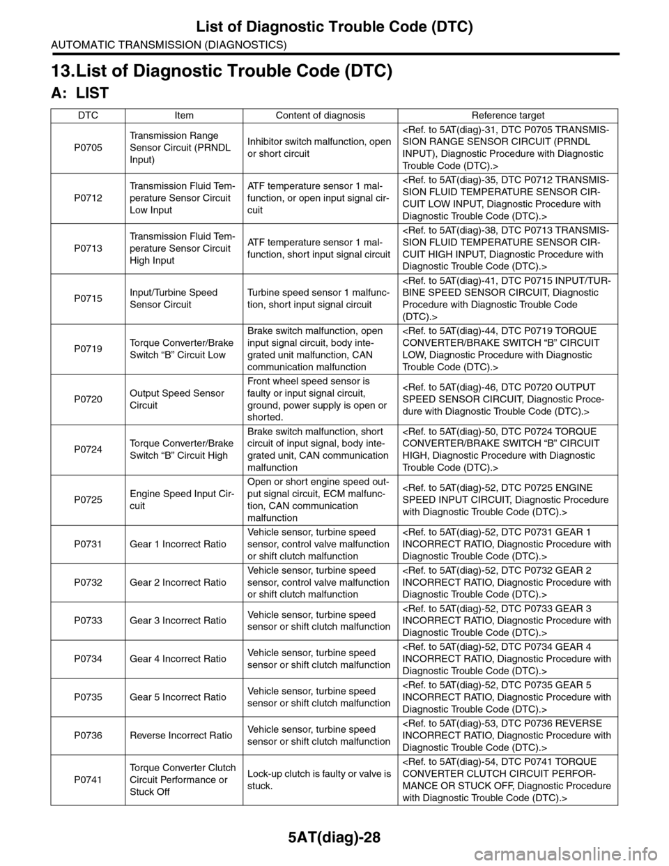
List of Diagnostic Trouble Code (DTC)
AUTOMATIC TRANSMISSION (DIAGNOSTICS)
13.List of Diagnostic Trouble Code (DTC)
A: LIST
DTC Item Content of diagnosis Reference target
P0705
Tr a n s m i s s i o n R a n g e
Sensor Circuit (PRNDL
Input)
Inhibitor switch malfunction, open
or short circuit
INPUT), Diagnostic Procedure with Diagnostic
Tr o u b l e C o d e ( D T C ) . >
P0712
Tr a n s m i s s i o n F l u i d Te m -
perature Sensor Circuit
Low Input
AT F t e m p e r a t u r e s e n s o r 1 m a l -
function, or open input signal cir-
cuit
CUIT LOW INPUT, Diagnostic Procedure with
Diagnostic Trouble Code (DTC).>
P0713
Tr a n s m i s s i o n F l u i d Te m -
perature Sensor Circuit
High Input
AT F t e m p e r a t u r e s e n s o r 1 m a l -
function, short input signal circuit
CUIT HIGH INPUT, Diagnostic Procedure with
Diagnostic Trouble Code (DTC).>
P0715Input/Turbine Speed
Sensor Circuit
Tu r b i n e s p e e d s e n s o r 1 m a l f u n c -
tion, short input signal circuit
Procedure with Diagnostic Trouble Code
(DTC).>
P0719To r q u e C o n v e r t e r / B r a k e
Switch “B” Circuit Low
Brake switch malfunction, open
input signal circuit, body inte-
grated unit malfunction, CAN
communication malfunction
LOW, Diagnostic Procedure with Diagnostic
Tr o u b l e C o d e ( D T C ) . >
P0720Output Speed Sensor
Circuit
Front wheel speed sensor is
faulty or input signal circuit,
ground, power supply is open or
shorted.
dure with Diagnostic Trouble Code (DTC).>
P0724To r q u e C o n v e r t e r / B r a k e
Switch “B” Circuit High
Brake switch malfunction, short
circuit of input signal, body inte-
grated unit, CAN communication
malfunction
HIGH, Diagnostic Procedure with Diagnostic
Tr o u b l e C o d e ( D T C ) . >
P0725Engine Speed Input Cir-
cuit
Open or short engine speed out-
put signal circuit, ECM malfunc-
tion, CAN communication
malfunction
with Diagnostic Trouble Code (DTC).>
P0731 Gear 1 Incorrect Ratio
Ve h i c l e s e n s o r, t u r b i n e s p e e d
sensor, control valve malfunction
or shift clutch malfunction
Diagnostic Trouble Code (DTC).>
P0732 Gear 2 Incorrect Ratio
Ve h i c l e s e n s o r, t u r b i n e s p e e d
sensor, control valve malfunction
or shift clutch malfunction
Diagnostic Trouble Code (DTC).>
P0733 Gear 3 Incorrect RatioVe h i c l e s e n s o r, t u r b i n e s p e e d
sensor or shift clutch malfunction
Diagnostic Trouble Code (DTC).>
P0734 Gear 4 Incorrect RatioVe h i c l e s e n s o r, t u r b i n e s p e e d
sensor or shift clutch malfunction
Diagnostic Trouble Code (DTC).>
P0735 Gear 5 Incorrect RatioVe h i c l e s e n s o r, t u r b i n e s p e e d
sensor or shift clutch malfunction
Diagnostic Trouble Code (DTC).>
P0736 Reverse Incorrect RatioVe h i c l e s e n s o r, t u r b i n e s p e e d
sensor or shift clutch malfunction
Diagnostic Trouble Code (DTC).>
P0741
To r q u e C o n v e r t e r C l u t c h
Circuit Performance or
Stuck Off
Lock-up clutch is faulty or valve is
stuck.
MANCE OR STUCK OFF, Diagnostic Procedure
with Diagnostic Trouble Code (DTC).>
Page 2146 of 2453
5AT(diag)-29
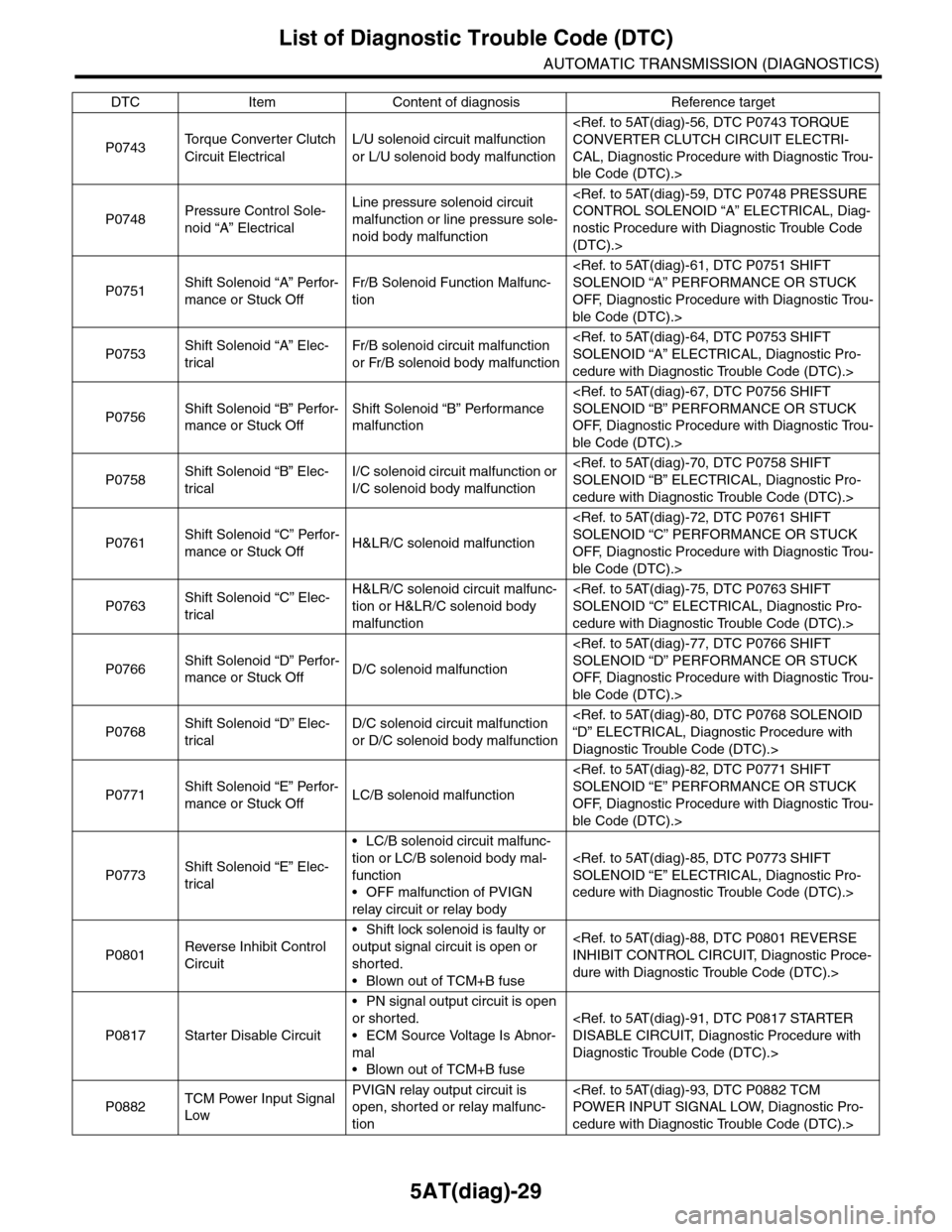
List of Diagnostic Trouble Code (DTC)
AUTOMATIC TRANSMISSION (DIAGNOSTICS)
P0743To r q u e C o n v e r t e r C l u t c h
Circuit Electrical
L/U solenoid circuit malfunction
or L/U solenoid body malfunction
CAL, Diagnostic Procedure with Diagnostic Trou-
ble Code (DTC).>
P0748Pressure Control Sole-
noid “A” Electrical
Line pressure solenoid circuit
malfunction or line pressure sole-
noid body malfunction
nostic Procedure with Diagnostic Trouble Code
(DTC).>
P0751Shift Solenoid “A” Perfor-
mance or Stuck Off
Fr/B Solenoid Function Malfunc-
tion
OFF, Diagnostic Procedure with Diagnostic Trou-
ble Code (DTC).>
P0753Shift Solenoid “A” Elec-
trical
Fr/B solenoid circuit malfunction
or Fr/B solenoid body malfunction
cedure with Diagnostic Trouble Code (DTC).>
P0756Shift Solenoid “B” Perfor-
mance or Stuck Off
Shift Solenoid “B” Performance
malfunction
OFF, Diagnostic Procedure with Diagnostic Trou-
ble Code (DTC).>
P0758Shift Solenoid “B” Elec-
trical
I/C solenoid circuit malfunction or
I/C solenoid body malfunction
cedure with Diagnostic Trouble Code (DTC).>
P0761Shift Solenoid “C” Perfor-
mance or Stuck OffH&LR/C solenoid malfunction
OFF, Diagnostic Procedure with Diagnostic Trou-
ble Code (DTC).>
P0763Shift Solenoid “C” Elec-
trical
H&LR/C solenoid circuit malfunc-
tion or H&LR/C solenoid body
malfunction
cedure with Diagnostic Trouble Code (DTC).>
P0766Shift Solenoid “D” Perfor-
mance or Stuck OffD/C solenoid malfunction
OFF, Diagnostic Procedure with Diagnostic Trou-
ble Code (DTC).>
P0768Shift Solenoid “D” Elec-
trical
D/C solenoid circuit malfunction
or D/C solenoid body malfunction
Diagnostic Trouble Code (DTC).>
P0771Shift Solenoid “E” Perfor-
mance or Stuck OffLC/B solenoid malfunction
OFF, Diagnostic Procedure with Diagnostic Trou-
ble Code (DTC).>
P0773Shift Solenoid “E” Elec-
trical
•LC/B solenoid circuit malfunc-
tion or LC/B solenoid body mal-
function
•OFF malfunction of PVIGN
relay circuit or relay body
cedure with Diagnostic Trouble Code (DTC).>
P0801Reverse Inhibit Control
Circuit
•Shift lock solenoid is faulty or
output signal circuit is open or
shorted.
•Blown out of TCM+B fuse
dure with Diagnostic Trouble Code (DTC).>
P0817 Starter Disable Circuit
•PN signal output circuit is open
or shorted.
•ECM Source Voltage Is Abnor-
mal
•Blown out of TCM+B fuse
Diagnostic Trouble Code (DTC).>
P0882TCM Power Input Signal
Low
PVIGN relay output circuit is
open, shorted or relay malfunc-
tion
cedure with Diagnostic Trouble Code (DTC).>
DTC Item Content of diagnosis Reference target
Page 2147 of 2453
5AT(diag)-30
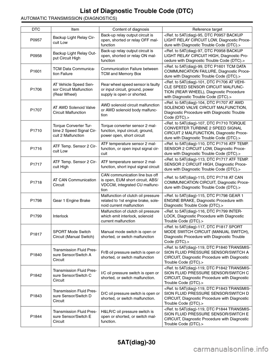
List of Diagnostic Trouble Code (DTC)
AUTOMATIC TRANSMISSION (DIAGNOSTICS)
P0957Backup Light Relay Cir-
cuit Low
Back-up relay output circuit is
open, shorted or relay OFF mal-
function
dure with Diagnostic Trouble Code (DTC).>
P0958Backup Light Relay Out-
put Circuit High
Back-up relay output circuit is
open, shorted or relay ON mal-
function
cedure with Diagnostic Trouble Code (DTC).>
P1601TCM Data Communica-
tion Failure
Communication Failure between
TCM and Memory Box
dure with Diagnostic Trouble Code (DTC).>
P1706
AT Ve h i c l e S p e e d S e n -
sor Circuit Malfunction
(Rear Wheel)
Rear wheel speed sensor is faulty
or input circuit, ground, power
supply is open or shorted.
TION (REAR WHEEL), Diagnostic Procedure
with Diagnostic Trouble Code (DTC).>
P1707AT A W D S o l e n o i d V a l v e
Circuit Malfunction
AWD solenoid circuit malfunction
or AWD solenoid body malfunc-
tion
Diagnostic Procedure with Diagnostic Trouble
Code (DTC).>
P1710
To r q u e C o n v e r t e r Tu r -
bine 2 Speed Signal Cir-
cuit 2 Malfunction
To r q u e c o n v e r t e r s e n s o r 2 m a l -
function, input circuit, ground,
power open, short circuit
CIRCUIT 2 MALFUNCTION, Diagnostic Proce-
dure with Diagnostic Trouble Code (DTC).>
P1716AT F Te m p . S e n s o r 2 C i r -
cuit Low
AT F t e m p e r a t u r e s e n s o r 2 m a l -
function, or open input signal cir-
cuit
dure with Diagnostic Trouble Code (DTC).>
P1717AT F Te m p . S e n s o r 2 C i r -
cuit High
AT F t e m p e r a t u r e s e n s o r 2 m a l -
function, short input signal circuit
dure with Diagnostic Trouble Code (DTC).>
P1718AT C A N C o m m u n i c a t i o n
Circuit
CAN communication line bus off
is open, EUM short circuit, ABS/
VDCCM, integrated CU malfunc-
tion
dure with Diagnostic Trouble Code (DTC).>
P1798 Gear 1 Engine Brake
Malfunction of clutch oil pressure
related to 1st engine brake, sole-
noid current malfunction
Diagnostic Trouble Code (DTC).>
P1799 Interlock
Malfunction of clutch oil pressure
which emit interlock, solenoid
current malfunction
Tr o u b l e C o d e ( D T C ) . >
P1817SPORT Mode Switch
Circuit (Manual Switch)
Manual mode switch is open or
shorted, or switch malfunction
Diagnostic Procedure with Diagnostic Trouble
Code (DTC).>
P1840
Tr a n s m i s s i o n F l u i d P r e s -
sure Sensor/Switch A
Circuit
Fr/B oil pressure switch is open or
shorted, or switch malfunction
CIRCUIT, Diagnostic Procedure with Diagnostic
Tr o u b l e C o d e ( D T C ) . >
P1842
Tr a n s m i s s i o n F l u i d P r e s -
sure Sensor/Switch C
Circuit
I/C oil pressure switch is open or
shorted, or switch malfunction.
CIRCUIT, Diagnostic Procedure with Diagnostic
Tr o u b l e C o d e ( D T C ) . >
P1843
Tr a n s m i s s i o n F l u i d P r e s -
sure Sensor/Switch D
Circuit
D/C oil pressure switch is open or
shorted, or switch malfunction.
CIRCUIT, Diagnostic Procedure with Diagnostic
Tr o u b l e C o d e ( D T C ) . >
P1844
Tr a n s m i s s i o n F l u i d P r e s -
sure Sensor/Switch E
Circuit
H&LR/C oil pressure switch is
open or shorted, or switch mal-
function.
CIRCUIT, Diagnostic Procedure with Diagnostic
Tr o u b l e C o d e ( D T C ) . >
DTC Item Content of diagnosis Reference target
Page 2148 of 2453
5AT(diag)-31
Diagnostic Procedure with Diagnostic Trouble Code (DTC)
AUTOMATIC TRANSMISSION (DIAGNOSTICS)
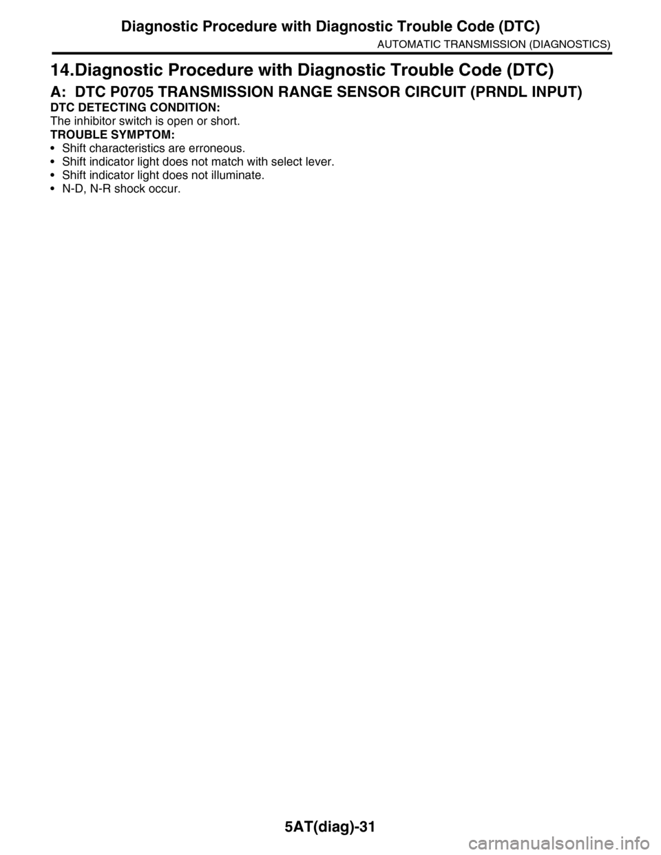
14.Diagnostic Procedure with Diagnostic Trouble Code (DTC)
A: DTC P0705 TRANSMISSION RANGE SENSOR CIRCUIT (PRNDL INPUT)
DTC DETECTING CONDITION:
The inhibitor switch is open or short.
TROUBLE SYMPTOM:
•Shift characteristics are erroneous.
•Shift indicator light does not match with select lever.
•Shift indicator light does not illuminate.
•N-D, N-R shock occur.
Page 2149 of 2453
5AT(diag)-32
Diagnostic Procedure with Diagnostic Trouble Code (DTC)
AUTOMATIC TRANSMISSION (DIAGNOSTICS)
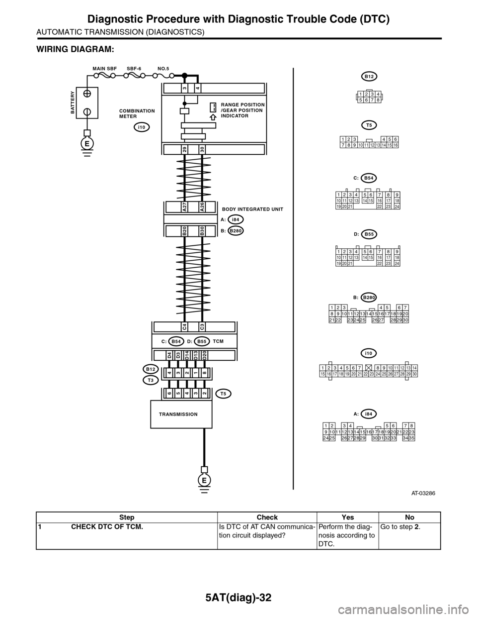
WIRING DIAGRAM:
AT-03286
i10
123456789101112131415161718192021222324252627282930
34
2930
COMBINATIONMETER
RANGE POSITION/GEAR POSITIONINDICATOR
i10
BODY INTEGRATED UNIT
i84A:
B280B:
A27A26
B20B30
C4C3
D3D13D20D4D14
31428
TRANSMISSION
TCMB54C:B55D:
B12
T3
BATTERY
MAIN SBF SBF-6 NO.5
E
E
i84
8765432122232120191615141312111093435333217301831292827262524
A:
B280
87654321
2223212019161514131211109173018292827262524
B:
B54
12789563410 11 1219 20 2113 14 15 16 17 18222324
C:
123410 11 1219 20 21135614 1578916 17 1822 23 24
B55D:
B12
12345678
123 68910 11 12 13 14451516
T5
7
53642T5
Step Check Yes No
1CHECK DTC OF TCM.Is DTC of AT CAN communica-
tion circuit displayed?
Pe r for m t h e d ia g -
nosis according to
DTC.
Go to step 2.
Page 2150 of 2453
5AT(diag)-33
Diagnostic Procedure with Diagnostic Trouble Code (DTC)
AUTOMATIC TRANSMISSION (DIAGNOSTICS)
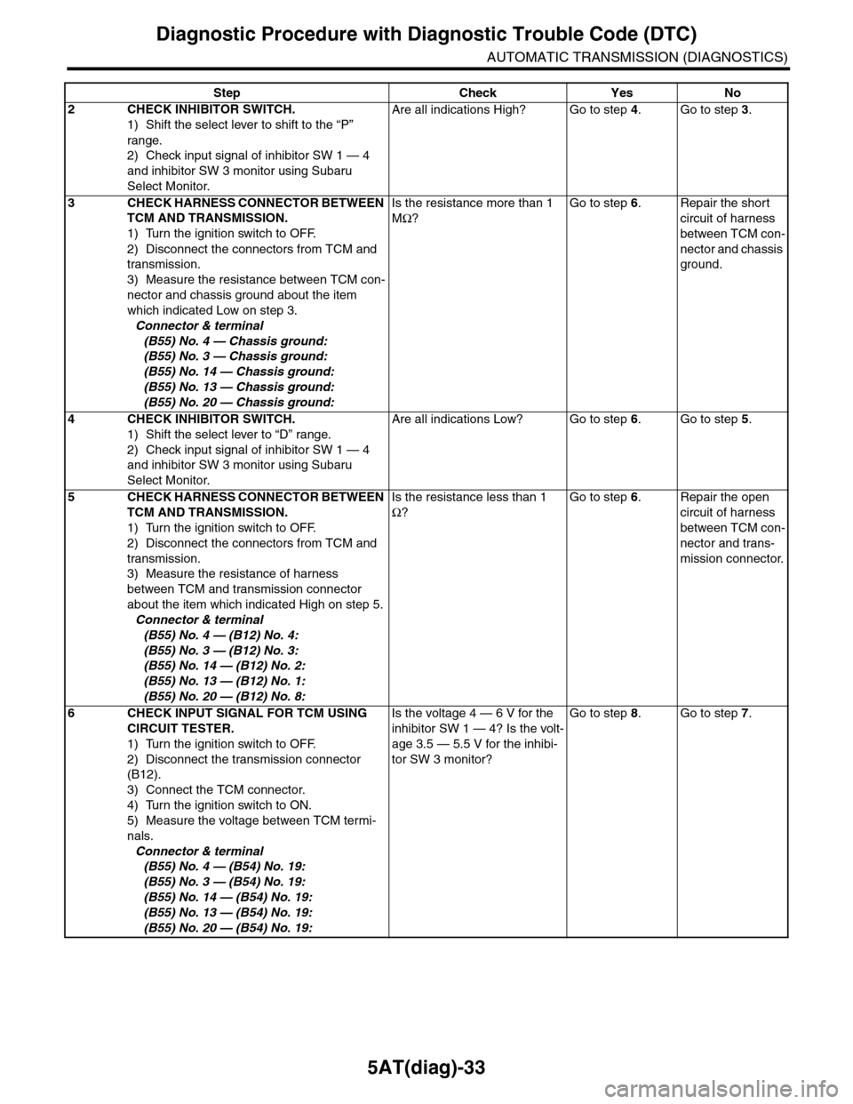
2CHECK INHIBITOR SWITCH.
1) Shift the select lever to shift to the “P”
range.
2) Check input signal of inhibitor SW 1 — 4
and inhibitor SW 3 monitor using Subaru
Select Monitor.
Are all indications High? Go to step 4.Go to step 3.
3CHECK HARNESS CONNECTOR BETWEEN
TCM AND TRANSMISSION.
1) Turn the ignition switch to OFF.
2) Disconnect the connectors from TCM and
transmission.
3) Measure the resistance between TCM con-
nector and chassis ground about the item
which indicated Low on step 3.
Connector & terminal
(B55) No. 4 — Chassis ground:
(B55) No. 3 — Chassis ground:
(B55) No. 14 — Chassis ground:
(B55) No. 13 — Chassis ground:
(B55) No. 20 — Chassis ground:
Is the resistance more than 1
MΩ?
Go to step 6.Repair the short
circuit of harness
between TCM con-
nector and chassis
ground.
4CHECK INHIBITOR SWITCH.
1) Shift the select lever to “D” range.
2) Check input signal of inhibitor SW 1 — 4
and inhibitor SW 3 monitor using Subaru
Select Monitor.
Are all indications Low? Go to step 6.Go to step 5.
5CHECK HARNESS CONNECTOR BETWEEN
TCM AND TRANSMISSION.
1) Turn the ignition switch to OFF.
2) Disconnect the connectors from TCM and
transmission.
3) Measure the resistance of harness
between TCM and transmission connector
about the item which indicated High on step 5.
Connector & terminal
(B55) No. 4 — (B12) No. 4:
(B55) No. 3 — (B12) No. 3:
(B55) No. 14 — (B12) No. 2:
(B55) No. 13 — (B12) No. 1:
(B55) No. 20 — (B12) No. 8:
Is the resistance less than 1
Ω?
Go to step 6.Repair the open
circuit of harness
between TCM con-
nector and trans-
mission connector.
6CHECK INPUT SIGNAL FOR TCM USING
CIRCUIT TESTER.
1) Turn the ignition switch to OFF.
2) Disconnect the transmission connector
(B12).
3) Connect the TCM connector.
4) Turn the ignition switch to ON.
5) Measure the voltage between TCM termi-
nals.
Connector & terminal
(B55) No. 4 — (B54) No. 19:
(B55) No. 3 — (B54) No. 19:
(B55) No. 14 — (B54) No. 19:
(B55) No. 13 — (B54) No. 19:
(B55) No. 20 — (B54) No. 19:
Is the voltage 4 — 6 V for the
inhibitor SW 1 — 4? Is the volt-
age 3.5 — 5.5 V for the inhibi-
tor SW 3 monitor?
Go to step 8.Go to step 7.
Step Check Yes No
Page 2151 of 2453
5AT(diag)-34
Diagnostic Procedure with Diagnostic Trouble Code (DTC)
AUTOMATIC TRANSMISSION (DIAGNOSTICS)
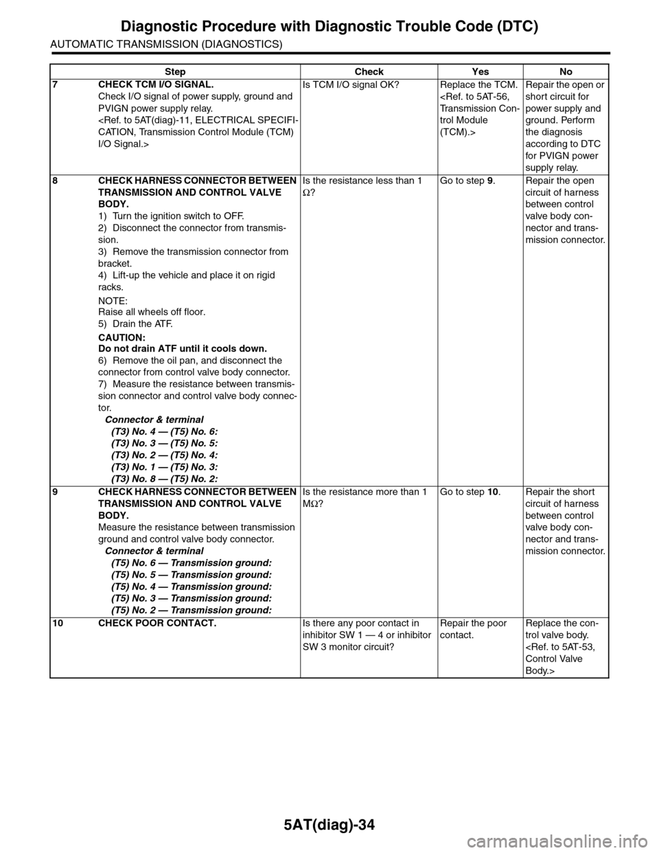
7CHECK TCM I/O SIGNAL.
Check I/O signal of power supply, ground and
PVIGN power supply relay.
I/O Signal.>
Is TCM I/O signal OK? Replace the TCM.
trol Module
(TCM).>
Repair the open or
short circuit for
power supply and
ground. Perform
the diagnosis
according to DTC
for PVIGN power
supply relay.
8CHECK HARNESS CONNECTOR BETWEEN
TRANSMISSION AND CONTROL VALVE
BODY.
1) Turn the ignition switch to OFF.
2) Disconnect the connector from transmis-
sion.
3) Remove the transmission connector from
bracket.
4) Lift-up the vehicle and place it on rigid
racks.
NOTE:
Raise all wheels off floor.
5) Drain the ATF.
CAUTION:Do not drain ATF until it cools down.
6) Remove the oil pan, and disconnect the
connector from control valve body connector.
7) Measure the resistance between transmis-
sion connector and control valve body connec-
tor.
Connector & terminal
(T3) No. 4 — (T5) No. 6:
(T3) No. 3 — (T5) No. 5:
(T3) No. 2 — (T5) No. 4:
(T3) No. 1 — (T5) No. 3:
(T3) No. 8 — (T5) No. 2:
Is the resistance less than 1
Ω?
Go to step 9.Repair the open
circuit of harness
between control
valve body con-
nector and trans-
mission connector.
9CHECK HARNESS CONNECTOR BETWEEN
TRANSMISSION AND CONTROL VALVE
BODY.
Measure the resistance between transmission
ground and control valve body connector.
Connector & terminal
(T5) No. 6 — Transmission ground:
(T5) No. 5 — Transmission ground:
(T5) No. 4 — Transmission ground:
(T5) No. 3 — Transmission ground:
(T5) No. 2 — Transmission ground:
Is the resistance more than 1
MΩ?
Go to step 10.Repair the short
circuit of harness
between control
valve body con-
nector and trans-
mission connector.
10 CHECK POOR CONTACT.Is there any poor contact in
inhibitor SW 1 — 4 or inhibitor
SW 3 monitor circuit?
Repair the poor
contact.
Replace the con-
trol valve body.
Body.>
Step Check Yes No
Page 2152 of 2453
5AT(diag)-35
Diagnostic Procedure with Diagnostic Trouble Code (DTC)
AUTOMATIC TRANSMISSION (DIAGNOSTICS)
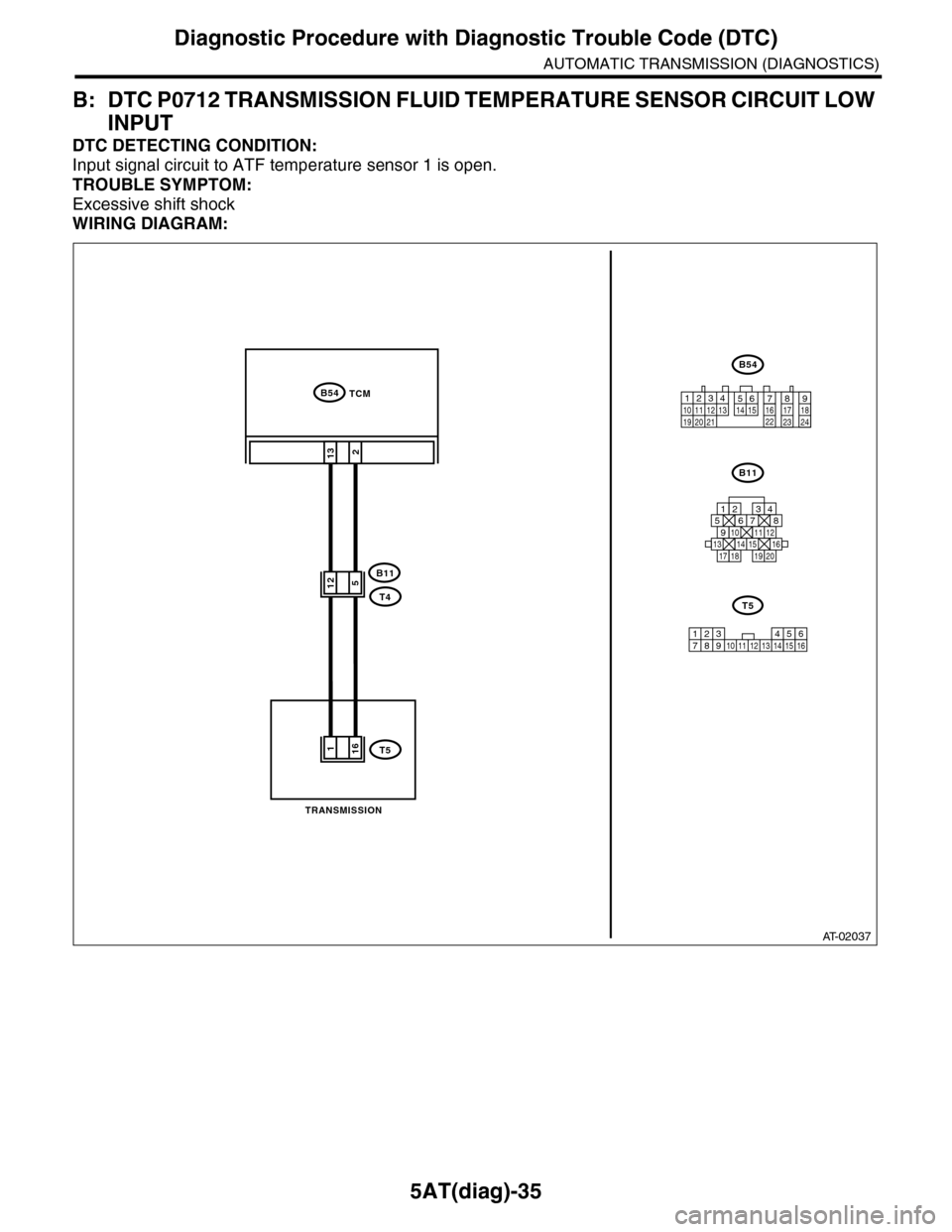
B: DTC P0712 TRANSMISSION FLUID TEMPERATURE SENSOR CIRCUIT LOW
INPUT
DTC DETECTING CONDITION:
Input signal circuit to ATF temperature sensor 1 is open.
TROUBLE SYMPTOM:
Excessive shift shock
WIRING DIAGRAM:
AT-02037
2
B54
B11
T4
T5
TCM
13
B54
B11
12789563410 11 1219 20 2113 14 15 16 17 18222324
TRANSMISSION
125678
131415169101112
34
17181920
512
161
123 68910 11 12 13 14451516
T5
7