Page 1886 of 2453
ME(H6DO)-20
General Description
MECHANICAL
2. GENERAL TOOL
E: PROCEDURE
It is possible to conduct the following service procedures with engine on vehicle, however, the procedures
described in this section are based on the condition that the engine is removed from vehicle.
•Camshaft
•Cylinder head
18471AA000 FUEL PIPE
ADAPTER
Used for measuring fuel pressure.
42075AG690 FUEL HOSE Used for measuring fuel pressure.
This is a genuine Subaru part.
TOOL NAME REMARKS
Compression gauge Used for measuring compression.
ILLUSTRATION TOOL NUMBER DESCRIPTION REMARKS
Page 1887 of 2453
ME(H6DO)-21
Compression
MECHANICAL
2. Compression
A: INSPECTION
CAUTION:
After warming-up, engine becomes very hot. Be
careful not to burn yourself during measure-
ment.
1) After warming-up the engine, turn the ignition
switch to OFF.
2) Make sure that the battery is fully charged.
3) Release the fuel pressure.
PRESSURE, PROCEDURE, Fuel.>
4) Remove all the spark plugs.
4, REMOVAL, Spark Plug.>
5) Check the starter motor for satisfactory perfor-
mance and operation.
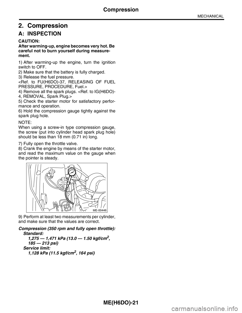
6) Hold the compression gauge tightly against the
spark plug hole.
NOTE:
When using a screw-in type compression gauge,
the screw (put into cylinder head spark plug hole)
should be less than 18 mm (0.71 in) long.
7) Fully open the throttle valve.
8) Crank the engine by means of the starter motor,
and read the maximum value on the gauge when
the pointer is steady.
9) Perform at least two measurements per cylinder,
and make sure that the values are correct.
Compression (350 rpm and fully open throttle):
Standard:
1,275 — 1,471 kPa (13.0 — 1.50 kgf/cm2,
185 — 213 psi)
Service limit:
1,128 kPa (11.5 kgf/cm2, 164 psi)
ME-00446
Page 1888 of 2453
ME(H6DO)-22
Idle Speed
MECHANICAL
3. Idle Speed
A: INSPECTION
1) Before checking the idle speed, check the fol-
lowing item:
(1) Check the air cleaner element is free from
clogging, ignition timing is correct, spark plugs
are in good condition, and hoses are connected
properly.
(2) Check the malfunction indicator light does
not illuminate.
2) Idle the engine.
3) Stop the engine, and turn the ignition switch to
OFF.
4) Insert the cartridge to Subaru Select Monitor.
5) Connect the Subaru Select Monitor to data link
connector.
6) Turn the ignition switch to ON and Subaru Select
Monitor switch to ON.
7) Select {Each System Check} in Main Menu.
8) Select {Engine} in Selection Menu.
9) Select {Current Data Display & Save} in Engine
Control System Diagnosis.
10) Select {Data Display} in Data Display Menu.
11) Start the engine, and read the engine idle
speed.
12) Check the idle speed when no-loaded. (Head-
light, heater fan, rear defroster, radiator fan, A/C
and etc. are OFF)
Idle speed [No load and gears in neutral]:
650±50 rpm
13) Check the idle speed when loaded. (Turn the A/
C switch to “ON” and operate the compressor for at
least one minute before measurement.)
Idle speed [A/C ON and gears in neutral]:
770±50 rpm
NOTE:
Idle speed cannot be adjusted manually, because
the idle speed is automatically adjusted. If the pre-
scribed idle speed cannot be maintained, refer to
General On-board Diagnosis Table under “Engine
Control System”.
sic Diagnostic Procedure.>
Page 1889 of 2453
ME(H6DO)-23
Ignition Timing
MECHANICAL
4. Ignition Timing
A: INSPECTION
CAUTION:
After warming-up, engine becomes very hot. Be
careful not to burn yourself at measurement.
1) Before checking the ignition timing, check the
following item:
(1) Check the air cleaner element is free from
clogging, spark plugs are in good condition, and
hoses are connected properly.
(2) Check the malfunction indicator light does
not illuminate.
2) Idle the engine.
3) Stop the engine, and turn the ignition switch to
OFF.
4) Insert the cartridge to Subaru Select Monitor.
5) Connect the Subaru Select Monitor to data link
connector.
6) Turn the ignition switch to ON and Subaru Select
Monitor switch to ON.
7) Select {Each System Check} in Main Menu.
8) Select {Engine} in Selection Menu.
9) Select {Current Data Display & Save} in Engine
Control System Diagnosis.
10) Select {Data Display} in Data Display Menu.
11) Start the engine and check the ignition timing at
idle speed.
Ignition timing [BTDC/rpm]:
15°±8°/650
If the timing is not correct, check the ignition control
system. Refer to Engine Control System.
EN(H6DO)(diag)-2, Basic Diagnostic Procedure.>
Page 1892 of 2453
ME(H6DO)-26
Fuel Pressure
MECHANICAL
7. Fuel Pressure
A: INSPECTION
WARNING:
Before removing the fuel pressure gauge, re-
lease the fuel pressure.
1) Release the fuel pressure.
PRESSURE, PROCEDURE, Fuel.>
2) Disconnect the fuel delivery hose and connect
fuel pressure gauge.
(1) Disconnect the fuel delivery hose using the
ST1.
ST1 42099AE000 CONNECTOR REMOVER
(2) Connect the fuel pressure meter using the
ST2 and ST3.
NOTE:
ST2 is a genuine Subaru part.
ST2 42075AG690 FUEL HOSE
ST3 18471AA000 FUEL PIPE ADAPTER
3) Install the fuse of fuel pump to main fuse box.
4) Start the engine.
5) Measure the fuel pressure after warming up the
engine.
Fuel pressure:
Standard: 338 — 348 kPa (3.4 — 3.5 kgf/cm2,
49 — 50.5 psi)
NOTE:
The fuel pressure gauge registers 10 to 20 kPa (0.1
to 0.2 kgf/cm2, 1 to 3 psi) higher than standard val-
ues during high-altitude operations.
(A) ST 2
(B) ST 3
ME-02666
(A)
(B)
FU-01122
Page 1898 of 2453
ME(H6DO)-32
Engine Assembly
MECHANICAL
10.Engine Assembly
A: REMOVAL
1) Set the vehicle on a lift.
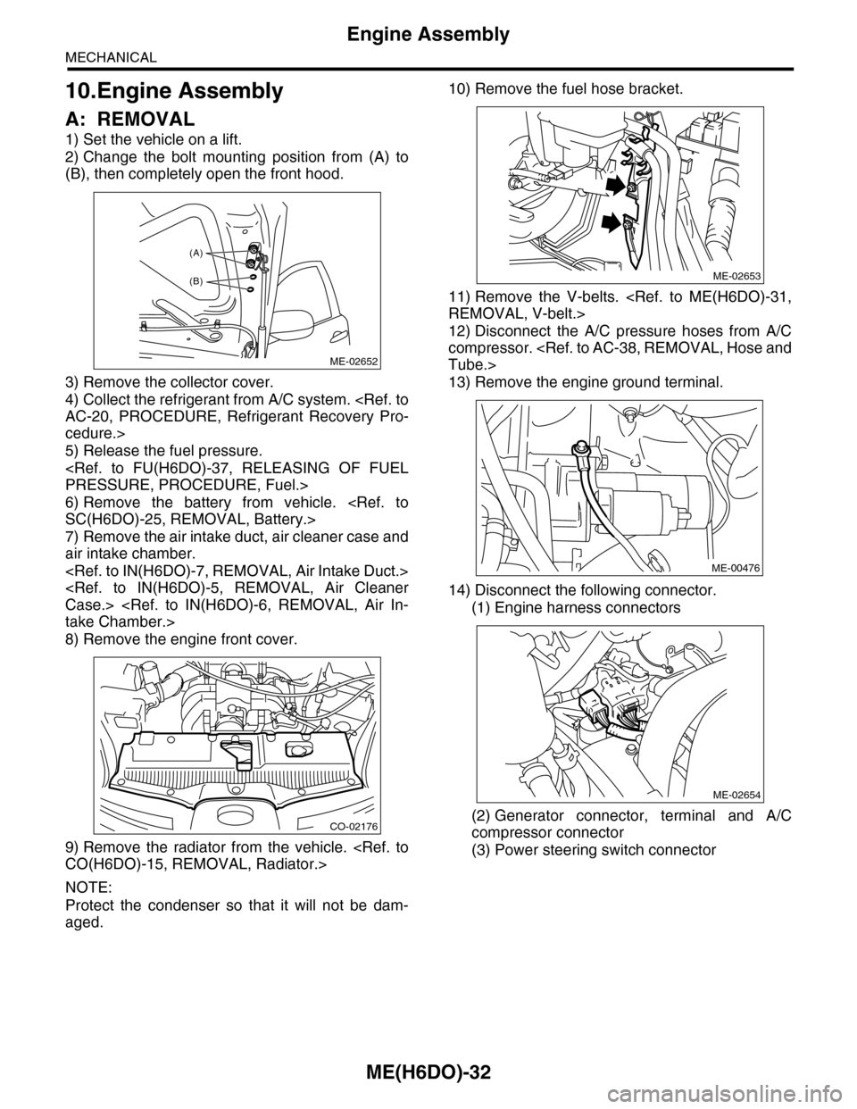
2) Change the bolt mounting position from (A) to
(B), then completely open the front hood.
3) Remove the collector cover.
4) Collect the refrigerant from A/C system.
AC-20, PROCEDURE, Refrigerant Recovery Pro-
cedure.>
5) Release the fuel pressure.
PRESSURE, PROCEDURE, Fuel.>
6) Remove the battery from vehicle.
SC(H6DO)-25, REMOVAL, Battery.>
7) Remove the air intake duct, air cleaner case and
air intake chamber.
Case.>
take Chamber.>
8) Remove the engine front cover.
9) Remove the radiator from the vehicle.
CO(H6DO)-15, REMOVAL, Radiator.>
NOTE:
Protect the condenser so that it will not be dam-
aged.
10) Remove the fuel hose bracket.
11) Remove the V-belts.
REMOVAL, V-belt.>
12) Disconnect the A/C pressure hoses from A/C
compressor.
Tube.>
13) Remove the engine ground terminal.
14) Disconnect the following connector.
(1) Engine harness connectors
(2) Generator connector, terminal and A/C
compressor connector
(3) Power steering switch connector
ME-02652
(A)
(B)
CO-02176
ME-02653
ME-00476
ME-02654
Page 1904 of 2453
ME(H6DO)-38
Engine Assembly
MECHANICAL
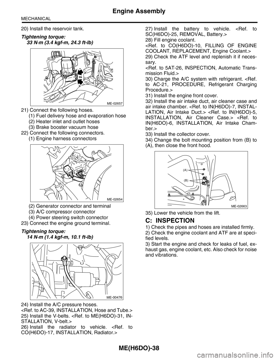
20) Install the reservoir tank.
Tightening torque:
33 N·m (3.4 kgf-m, 24.3 ft-lb)
21) Connect the following hoses.
(1) Fuel delivery hose and evaporation hose
(2) Heater inlet and outlet hoses
(3) Brake booster vacuum hose
22) Connect the following connectors.
(1) Engine harness connectors
(2) Generator connector and terminal
(3) A/C compressor connector
(4) Power steering switch connector
23) Connect the engine ground terminal.
Tightening torque:
14 N·m (1.4 kgf-m, 10.1 ft-lb)
24) Install the A/C pressure hoses.
25) Install the V-belts.
STALLATION, V-belt.>
26) Install the radiator to vehicle.
CO(H6DO)-17, INSTALLATION, Radiator.>
27) Install the battery to vehicle.
SC(H6DO)-25, REMOVAL, Battery.>
28) Fill engine coolant.
COOLANT, REPLACEMENT, Engine Coolant.>
29) Check the ATF level and replenish it if neces-
sary.
mission Fluid.>
30) Charge the A/C system with refrigerant.
to AC-21, PROCEDURE, Refrigerant Charging
Procedure.>
31) Install the engine front cover.
32) Install the air intake duct, air cleaner case and
air intake chamber.
LATION, Air Intake Duct.>
INSTALLATION, Air Cleaner Case.>
IN(H6DO)-6, INSTALLATION, Air Intake Cham-
ber.>
33) Install the collector cover.
34) Change the bolt mounting position from (B) to
(A), then close the front hood.
35) Lower the vehicle from the lift.
C: INSPECTION
1) Check the pipes and hoses are installed firmly.
2) Check the engine coolant and ATF are at speci-
fied levels.
3) Start the engine and check for leaks of fuel, ex-
haust gas, engine coolant, etc. Also check for noise
and vibrations.
ME-02657
ME-02654
ME-00476
ME-02663
(A)
(B)
Page 1928 of 2453
ME(H6DO)-62
Cylinder Block
MECHANICAL
21.Cylinder Block
A: REMOVAL
NOTE:
Before conducting this procedure, drain the engine
oil completely.
1) Remove the crank pulley.
41, REMOVAL, Crank Pulley.>
2) Remove the front chain cover.
ME(H6DO)-42, REMOVAL, Front Chain Cover.>
3) Remove the timing chain assembly.
Assembly.>
4) Remove the cam sprocket.
et.>
5) Remove the crank sprocket.
et.>
6) Remove the rear chain cover.
Cover.>
7) Remove the camshaft.
REMOVAL, Camshaft.>
8) Remove the cylinder head.
57, REMOVAL, Cylinder Head.>
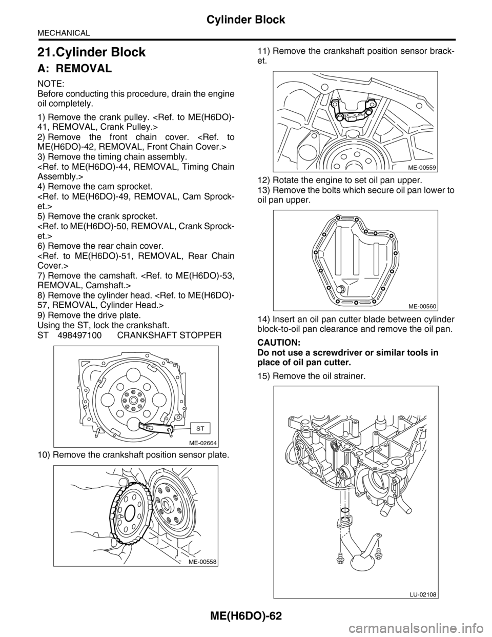
9) Remove the drive plate.
Using the ST, lock the crankshaft.
ST 498497100 CRANKSHAFT STOPPER
10) Remove the crankshaft position sensor plate.
11) Remove the crankshaft position sensor brack-
et.
12) Rotate the engine to set oil pan upper.
13) Remove the bolts which secure oil pan lower to
oil pan upper.
14) Insert an oil pan cutter blade between cylinder
block-to-oil pan clearance and remove the oil pan.
CAUTION:
Do not use a screwdriver or similar tools in
place of oil pan cutter.
15) Remove the oil strainer.
ME-02664
ST
ME-00558
ME-00559
ME-00560
LU-02108