Page 1725 of 2453

GD(H6DO)-113
Diagnostic Trouble Code (DTC) Detecting Criteria
GENERAL DESCRIPTION
6. DTC CLEAR CONDITION
•When the OK idling cycle is completed 40 times in a row
•When “Clear Memory” is performed
7. MALFUNCTION INDICATOR LIGHT CLEAR CONDITIONS
•When the OK driving cycle is completed 3 times in a row
•When “Clear Memory” is performed
8. FAIL SAFE
Knocking compensation
When normal: Learning ignition advance angle value = knock F/B advance angle + entire learning advance
angle value + portional learning advance angle value
Failure: Learning ignition advance angle value = –5.0°CA
Knock F/B advancing angle = 0°CA
Whole learning prohibited
Portional learning prohibited
9. ECM OPERATION AT DTC SETTING
Memorize the freeze frame data. (For test mode $02)
BV:DTC P0332 KNOCK SENSOR 2 CIRCUIT LOW INPUT (BANK 2)
1. OUTLINE OF DIAGNOSIS
NOTE:
For the diagnostic procedure, refer to DTC P0327.
1 CIRCUIT LOW INPUT (BANK 1 OR SINGLE SENSOR), Diagnostic Trouble Code (DTC) Detecting Crite-
ria.>
BW:DTC P0333 KNOCK SENSOR 2 CIRCUIT HIGH INPUT (BANK 2)
1. OUTLINE OF DIAGNOSIS
NOTE:
For the diagnostic procedure, refer to DTC P0328.
1 CIRCUIT HIGH INPUT (BANK 1 OR SINGLE SENSOR), Diagnostic Trouble Code (DTC) Detecting Crite-
ria.>
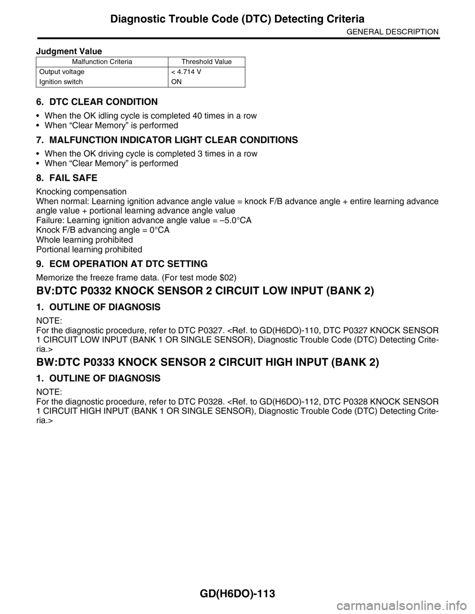
Judgment Value
Malfunction Criteria Threshold Value
Output voltage < 4.714 V
Ignition switch ON
Page 1732 of 2453
GD(H6DO)-120
Diagnostic Trouble Code (DTC) Detecting Criteria
GENERAL DESCRIPTION
CA:DTC P0345 CAMSHAFT POSITION SENSOR “A” CIRCUIT (BANK 2)
1. OUTLINE OF DIAGNOSIS
NOTE:
For the diagnostic procedure, refer to DTC P0340.
SITION SENSOR “A” CIRCUIT (BANK 1 OR SINGLE SENSOR), Diagnostic Trouble Code (DTC) Detecting
Criteria.>
Page 1798 of 2453
GD(H6DO)-186
Diagnostic Trouble Code (DTC) Detecting Criteria
GENERAL DESCRIPTION
DH:DTC P1154 O2 SENSOR CIRCUIT RANGE/PERFORMANCE (LOW) (BANK 2
SENSOR 1)
1. OUTLINE OF DIAGNOSIS
NOTE:
For the diagnostic procedure, refer to DTC P1152.
CUIT RANGE/PERFORMANCE (LOW) (BANK 1 SENSOR 1), Diagnostic Trouble Code (DTC) Detecting
Criteria.>
DI: DTC P1155 O2 SENSOR CIRCUIT RANGE/PERFORMANCE (HIGH) (BANK 2
SENSOR 1)
1. OUTLINE OF DIAGNOSIS
NOTE:
For the diagnostic procedure, refer to DTC P1153.
CUIT RANGE/PERFORMANCE (HIGH) (BANK 1 SENSOR 1), Diagnostic Trouble Code (DTC) Detecting
Criteria.>
Page 1808 of 2453
GD(H6DO)-196
Diagnostic Trouble Code (DTC) Detecting Criteria
GENERAL DESCRIPTION
DW:DTC P2092 OCV SOLENOID VALVE SIGNAL A CIRCUIT OPEN (BANK 2)
1. OUTLINE OF DIAGNOSIS
NOTE:
For the detection procedure, refer to DTC P2088.
VALVE SIGNAL A CIRCUIT OPEN (BANK 1), Diagnostic Trouble Code (DTC) Detecting Criteria.>
DX:DTC P2093 OCV SOLENOID VALVE SIGNAL A CIRCUIT SHORT (BANK 2)
1. OUTLINE OF DIAGNOSIS
NOTE:
For the detection procedure, refer to DTC P2089.
VALVE SIGNAL A CIRCUIT SHORT (BANK 1), Diagnostic Trouble Code (DTC) Detecting Criteria.>
Page 1812 of 2453

GD(H6DO)-200
Diagnostic Trouble Code (DTC) Detecting Criteria
GENERAL DESCRIPTION
Time Needed for Diagnosis: 5 seconds
Malfunction Indicator Light Illumination: Illuminates when malfunctions occur in 2 continuous driving cy-
cles.
6. DTC CLEAR CONDITION
•When the OK idling cycle is completed 40 times in a row
•When “Clear Memory” is performed
7. MALFUNCTION INDICATOR LIGHT CLEAR CONDITIONS
•When similar driving conditions are repeated 3 times and the result is OK.
•When “Clear Memory” is performed
8. FAIL SAFE
None
9. ECM OPERATION AT DTC SETTING
Memorize the freeze frame data. (For test mode $02)
EA:DTC P2098 POST CATALYST FUEL TRIM SYSTEM TOO LEAN (BANK 2)
1. OUTLINE OF DIAGNOSIS
NOTE:
For the detection procedure, refer to DTC P2096.
FUEL TRIM SYSTEM TOO LEAN (BANK 1), Diagnostic Trouble Code (DTC) Detecting Criteria.>
EB:DTC P2099 POST CATALYST FUEL TRIM SYSTEM TOO RICH (BANK 2)
1. OUTLINE OF DIAGNOSIS
NOTE:
For the detection procedure, refer to DTC P2097.
FUEL TRIM SYSTEM TOO RICH (BANK 1), Diagnostic Trouble Code (DTC) Detecting Criteria.>
Page 1842 of 2453
IG(H6DO)-7
Ignition Coil & Ignitor Assembly
IGNITION
3. Ignition Coil & Ignitor Assem-
bly
A: REMOVAL
Direct ignition type has been adopted. Refer to
“Spark Plug” for removal procedure.
IG(H6DO)-4, REMOVAL, Spark Plug.>
B: INSTALLATION
Install in the reverse order of removal.
Tightening torque:
16 N·m (1.6 kgf-m, 11.7 ft-lb)
C: INSPECTION
For inspection procedure, refer to “Diagnostics for
Engine Starting Failure.”
63, IGNITION CONTROL SYSTEM, Diagnostics
for Engine Starting Failure.>
Page 1850 of 2453
IN(H6DO)-8
Resonator Chamber
INTAKE (INDUCTION)
6. Resonator Chamber
A: REMOVAL
The resonator chamber and air cleaner case are in-
tegrated into one unit; therefore, refer to “Air Clean-
er Case” for removal procedure.
IN(H6DO)-5, REMOVAL, Air Cleaner Case.>
B: INSTALLATION
The resonator chamber and air cleaner case are in-
tegrated into one unit; therefore, refer to “Air Clean-
er Case” for installation procedure.
IN(H6DO)-5, INSTALLATION, Air Cleaner Case.>
C: INSPECTION
Check for cracks or loose connections.
Page 1859 of 2453

LU(H6DO)-10
Oil Pump Relief Valve
LUBRICATION
5. Oil Pump Relief Valve
A: REMOVAL
1. REAR CHAIN COVER SIDE
Oil pump relief valve is integrated into oil pump cov-
er as one unit; therefore, refer to “Oil Pump” for re-
moval procedure.
REMOVAL, Oil Pump.>
2. OIL PAN UPPER SIDE
1) Remove the oil pan.
MOVAL, Oil Pan and Strainer.>
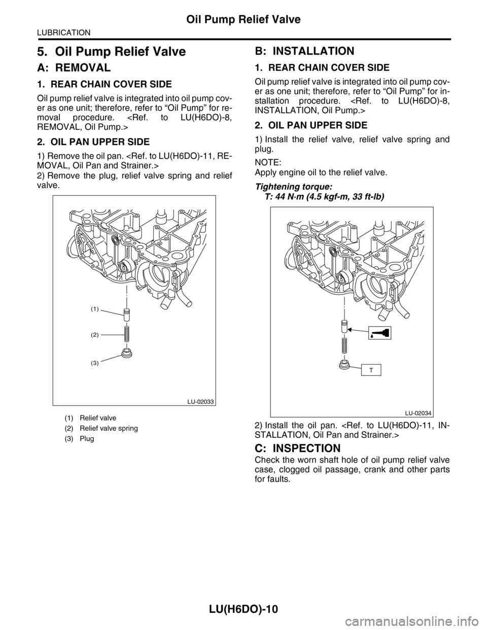
2) Remove the plug, relief valve spring and relief
valve.
B: INSTALLATION
1. REAR CHAIN COVER SIDE
Oil pump relief valve is integrated into oil pump cov-
er as one unit; therefore, refer to “Oil Pump” for in-
stallation procedure.
INSTALLATION, Oil Pump.>
2. OIL PAN UPPER SIDE
1) Install the relief valve, relief valve spring and
plug.
NOTE:
Apply engine oil to the relief valve.
Tightening torque:
T: 44 N·m (4.5 kgf-m, 33 ft-lb)
2) Install the oil pan.
STALLATION, Oil Pan and Strainer.>
C: INSPECTION
Check the worn shaft hole of oil pump relief valve
case, clogged oil passage, crank and other parts
for faults.
(1) Relief valve
(2) Relief valve spring
(3) Plug
(1)
LU-02033
(2)
(3)
LU-02034
T