2009 SUBARU TRIBECA differential
[x] Cancel search: differentialPage 2054 of 2453
5AT-38
Automatic Transmission Assembly
AUTOMATIC TRANSMISSION
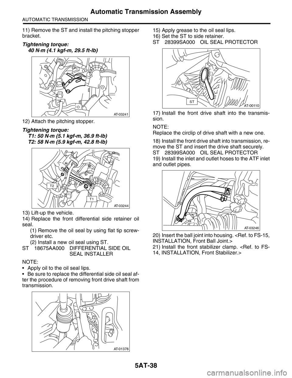
11) Remove the ST and install the pitching stopper
bracket.
Tightening torque:
40 N·m (4.1 kgf-m, 29.5 ft-lb)
12) Attach the pitching stopper.
Tightening torque:
T1: 50 N·m (5.1 kgf-m, 36.9 ft-lb)
T2: 58 N·m (5.9 kgf-m, 42.8 ft-lb)
13) Lift-up the vehicle.
14) Replace the front differential side retainer oil
seal.
(1) Remove the oil seal by using flat tip screw-
driver etc.
(2) Install a new oil seal using ST.
ST 18675AA000 DIFFERENTIAL SIDE OIL
SEAL INSTALLER
NOTE:
•Apply oil to the oil seal lips.
•Be sure to replace the differential side oil seal af-
ter the procedure of removing front drive shaft from
transmission.
15) Apply grease to the oil seal lips.
16) Set the ST to side retainer.
ST 28399SA000 OIL SEAL PROTECTOR
17) Install the front drive shaft into the transmis-
sion.
NOTE:
Replace the circlip of drive shaft with a new one.
18) Install the front drive shaft into transmission, re-
move the ST and insert the drive shaft securely.
ST 28399SA000 OIL SEAL PROTECTOR
19) Install the inlet and outlet hoses to the ATF inlet
and outlet pipes.
20) Insert the ball joint into housing.
21) Install the front stabilizer clamp.
AT-03241
AT-03244
T1
T2
AT-01378
AT-00110ST
AT-03246
Page 2061 of 2453
5AT-45
Differential Side Retainer Oil Seal
AUTOMATIC TRANSMISSION
12.Differential Side Retainer Oil
Seal
A: INSPECTION
Check for leakage of gear oil from differential side
retainer oil seal part. If there is an oil leak, replace
the oil seal.
B: REPLACEMENT
1) Lift-up the vehicle.
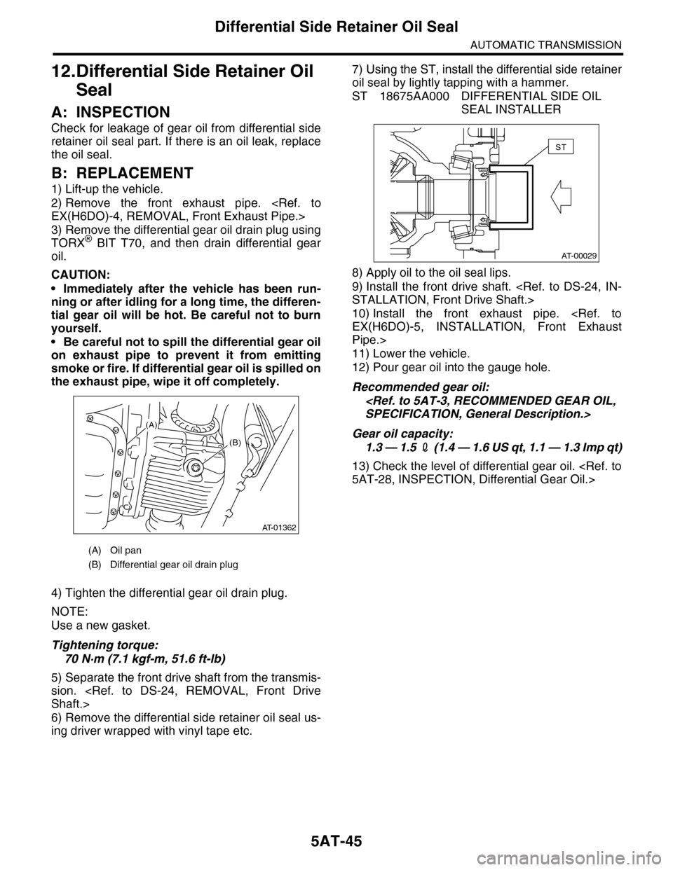
2) Remove the front exhaust pipe.
3) Remove the differential gear oil drain plug using
TORX® BIT T70, and then drain differential gear
oil.
CAUTION:
•Immediately after the vehicle has been run-
ning or after idling for a long time, the differen-
tial gear oil will be hot. Be careful not to burn
yourself.
•Be careful not to spill the differential gear oil
on exhaust pipe to prevent it from emitting
smoke or fire. If differential gear oil is spilled on
the exhaust pipe, wipe it off completely.
4) Tighten the differential gear oil drain plug.
NOTE:
Use a new gasket.
Tightening torque:
70 N·m (7.1 kgf-m, 51.6 ft-lb)
5) Separate the front drive shaft from the transmis-
sion.
6) Remove the differential side retainer oil seal us-
ing driver wrapped with vinyl tape etc.
7) Using the ST, install the differential side retainer
oil seal by lightly tapping with a hammer.
ST 18675AA000 DIFFERENTIAL SIDE OIL
SEAL INSTALLER
8) Apply oil to the oil seal lips.
9) Install the front drive shaft.
10) Install the front exhaust pipe.
Pipe.>
11) Lower the vehicle.
12) Pour gear oil into the gauge hole.
Recommended gear oil:
Gear oil capacity:
1.3 — 1.5 2 ( 1 . 4 — 1 . 6 U S q t , 1 . 1 — 1 . 3 I m p q t )
13) Check the level of differential gear oil.
(A) Oil pan
(B) Differential gear oil drain plug
(B)
AT-01362
(A)
AT-00029
ST
Page 2063 of 2453
5AT-47
Front Vehicle Speed Sensor
AUTOMATIC TRANSMISSION
14.Front Vehicle Speed Sensor
A: REMOVAL
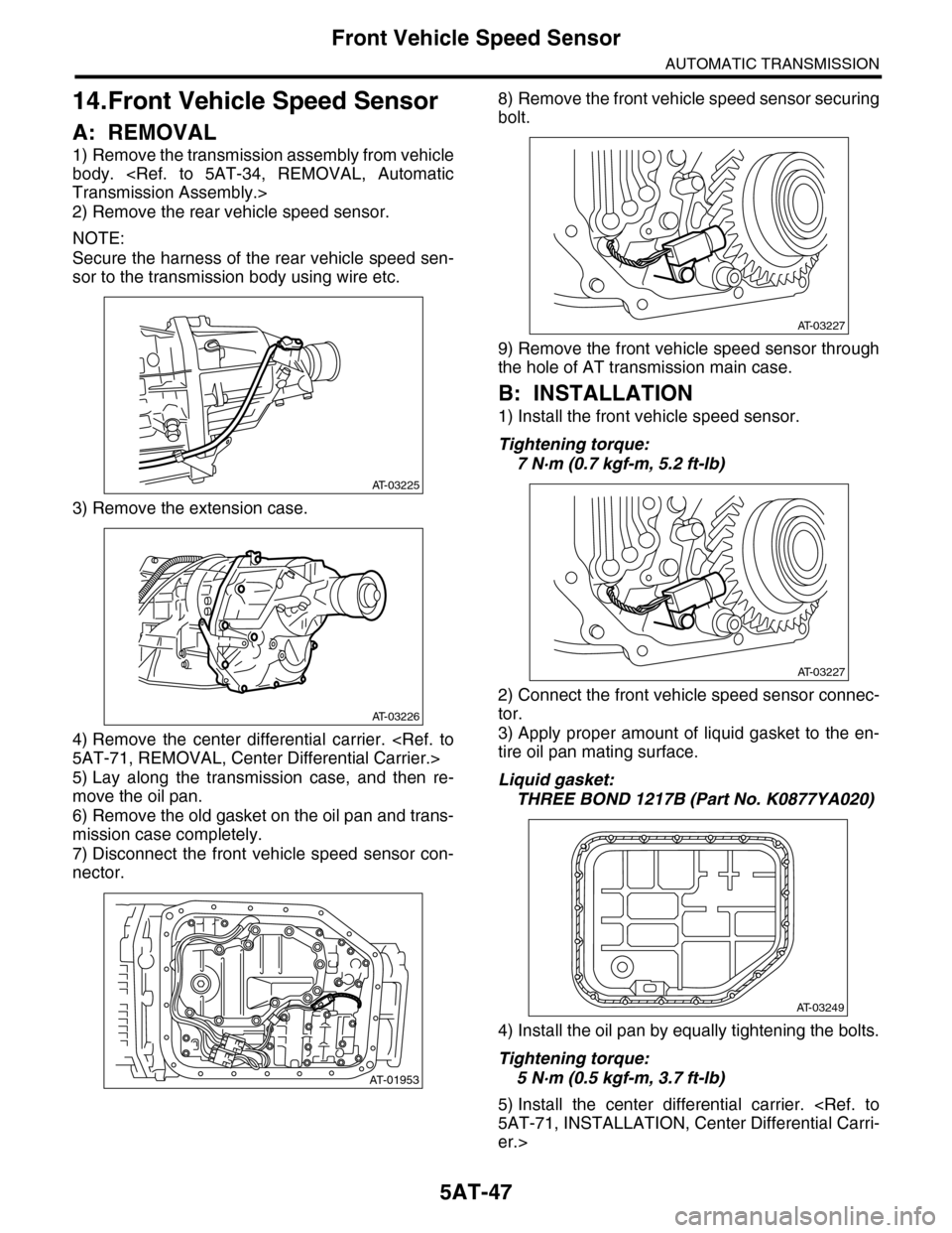
1) Remove the transmission assembly from vehicle
body.
2) Remove the rear vehicle speed sensor.
NOTE:
Secure the harness of the rear vehicle speed sen-
sor to the transmission body using wire etc.
3) Remove the extension case.
4) Remove the center differential carrier.
5) Lay along the transmission case, and then re-
move the oil pan.
6) Remove the old gasket on the oil pan and trans-
mission case completely.
7) Disconnect the front vehicle speed sensor con-
nector.
8) Remove the front vehicle speed sensor securing
bolt.
9) Remove the front vehicle speed sensor through
the hole of AT transmission main case.
B: INSTALLATION
1) Install the front vehicle speed sensor.
Tightening torque:
7 N·m (0.7 kgf-m, 5.2 ft-lb)
2) Connect the front vehicle speed sensor connec-
tor.
3) Apply proper amount of liquid gasket to the en-
tire oil pan mating surface.
Liquid gasket:
THREE BOND 1217B (Part No. K0877YA020)
4) Install the oil pan by equally tightening the bolts.
Tightening torque:
5 N·m (0.5 kgf-m, 3.7 ft-lb)
5) Install the center differential carrier.
er.>
AT-03225
AT-03226
AT-01953
AT-03227
AT-03227
AT-03249
Page 2081 of 2453
5AT-65
Transfer Clutch
AUTOMATIC TRANSMISSION
25.Transfer Clutch
A: REMOVAL
1) Remove the transmission assembly from vehicle
body.
2) Remove the extension case, and then remove
the transfer clutch.
B: INSTALLATION
1) Select the rear drive shaft shim.
2) Select driven plate No. 3.
3) Install the extension case.
4) Install the transmission assembly to the vehicle.
C: INSPECTION
•Inspect the drive plate facing for wear and dam-
age.
•Make sure the snap ring is not worn and the re-
turn spring has no permanent distortion, damage,
or deformation.
•Check that the D-ring is not damaged.
•Inspect the extension end play, and adjust it to
within the standard value.
D: ADJUSTMENT
1. REAR DRIVE SHAFT SHIM SELECTION
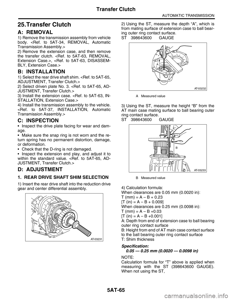
1) Insert the rear drive shaft into the reduction drive
gear and center differential assembly.
2) Using the ST, measure the depth “A”, which is
from mating surface of extension case to ball bear-
ing outer ring contact surface.
ST 398643600 GAUGE
3) Using the ST, measure the height “B” from the
AT main case mating surface to ball bearing outer
ring contact surface.
ST 398643600 GAUGE
4) Calculation formula:
When clearances are 0.05 mm (0.0020 in):
T (mm) = A – B + 0.23
[T (in) = A – B + 0.009]
When clearances are 0.25 mm (0.0098 in):
T (mm) = A – B +0.03
[T (in) = A – B +0.001]
A: Depth from end of extension case to ball bearing
outer ring contact surface
B: Height from end of AT main case contact surface
to the ball bearing outer ring contact surface
T: Shim thickness
Specification:
0.05 — 0.25 mm (0.0020 — 0.0098 in)
NOTE:
Calculation formula for “T” above is applied when
measuring with the ST (398643600 GAUGE).
When not using the ST,
AT-03231
AMeasured value
BMeasured value
AT-03232
A
AT-03233
B
Page 2082 of 2453
5AT-66
Transfer Clutch
AUTOMATIC TRANSMISSION
When clearances are 0.05 mm (0.0020 in):
T (mm) = (A – α) – ((B – β) – 0.28) – 0.05
[T (in) = (A – α) – ((B – β) – 0.011) – 0.0020]
When clearances are 0.25 mm (0.0098 in):
T (mm) = (A – α) – ((B – β) – 0.28) – 0.25
[T (in) = (A – α) – ((B – β) – 0.011) – 0.0098]
is applied.
T: Shim thickness
A: Depth from end of extension case to ball bearing
outer ring contact surface
B: Height from end of AT main case contact surface
to the ball bearing outer ring contact surface
α: Thickness of collar used when measuring “A”
β: Thickness of collar used when measuring “B”
0.28 (0.011): Gasket thickness (Unit mm (in))
2. SELECTION OF DRIVEN PLATE NO. 3
1) Install the drive plate and driven plate to the cen-
ter differential carrier.
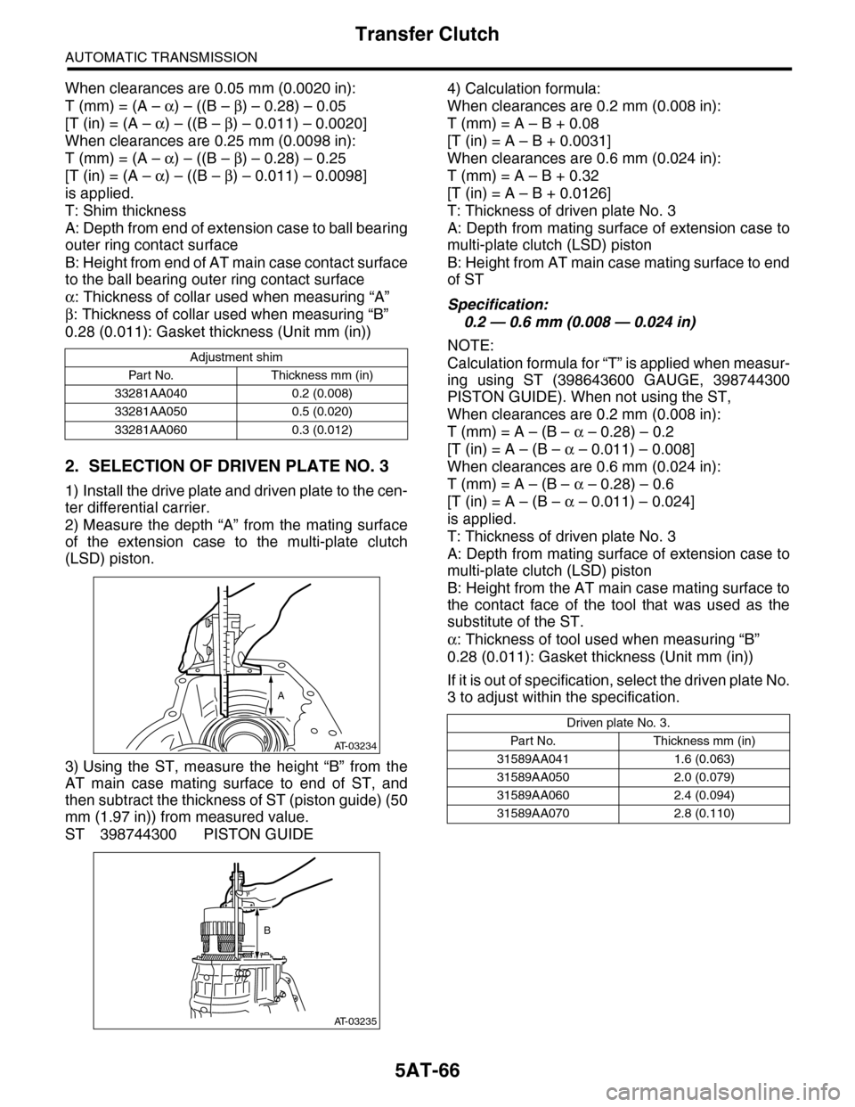
2) Measure the depth “A” from the mating surface
of the extension case to the multi-plate clutch
(LSD) piston.
3) Using the ST, measure the height “B” from the
AT main case mating surface to end of ST, and
then subtract the thickness of ST (piston guide) (50
mm (1.97 in)) from measured value.
ST 398744300 PISTON GUIDE
4) Calculation formula:
When clearances are 0.2 mm (0.008 in):
T (mm) = A – B + 0.08
[T (in) = A – B + 0.0031]
When clearances are 0.6 mm (0.024 in):
T (mm) = A – B + 0.32
[T (in) = A – B + 0.0126]
T: Thickness of driven plate No. 3
A: Depth from mating surface of extension case to
multi-plate clutch (LSD) piston
B: Height from AT main case mating surface to end
of ST
Specification:
0.2 — 0.6 mm (0.008 — 0.024 in)
NOTE:
Calculation formula for “T” is applied when measur-
ing using ST (398643600 GAUGE, 398744300
PISTON GUIDE). When not using the ST,
When clearances are 0.2 mm (0.008 in):
T (mm) = A – (B – α – 0.28) – 0.2
[T (in) = A – (B – α – 0.011) – 0.008]
When clearances are 0.6 mm (0.024 in):
T (mm) = A – (B – α – 0.28) – 0.6
[T (in) = A – (B – α – 0.011) – 0.024]
is applied.
T: Thickness of driven plate No. 3
A: Depth from mating surface of extension case to
multi-plate clutch (LSD) piston
B: Height from the AT main case mating surface to
the contact face of the tool that was used as the
substitute of the ST.
α: Thickness of tool used when measuring “B”
0.28 (0.011): Gasket thickness (Unit mm (in))
If it is out of specification, select the driven plate No.
3 to adjust within the specification.
Adjustment shim
Par t No. Thickness mm (in)
33281AA040 0.2 (0.008)
33281AA050 0.5 (0.020)
33281AA060 0.3 (0.012)
AT-03234
A
AT-03235
B
Driven plate No. 3.
Par t N o. Thickness mm (in)
31589AA041 1.6 (0.063)
31589AA050 2.0 (0.079)
31589AA060 2.4 (0.094)
31589AA070 2.8 (0.110)
Page 2084 of 2453
5AT-68
Reduction Driven Gear
AUTOMATIC TRANSMISSION
27.Reduction Driven Gear
A: REMOVAL
1) Remove the transmission assembly from vehicle
body.
2) Remove the rear wheel speed sensor, and sep-
arate the extension case from transmission case.
3) Remove the center differential carrier.
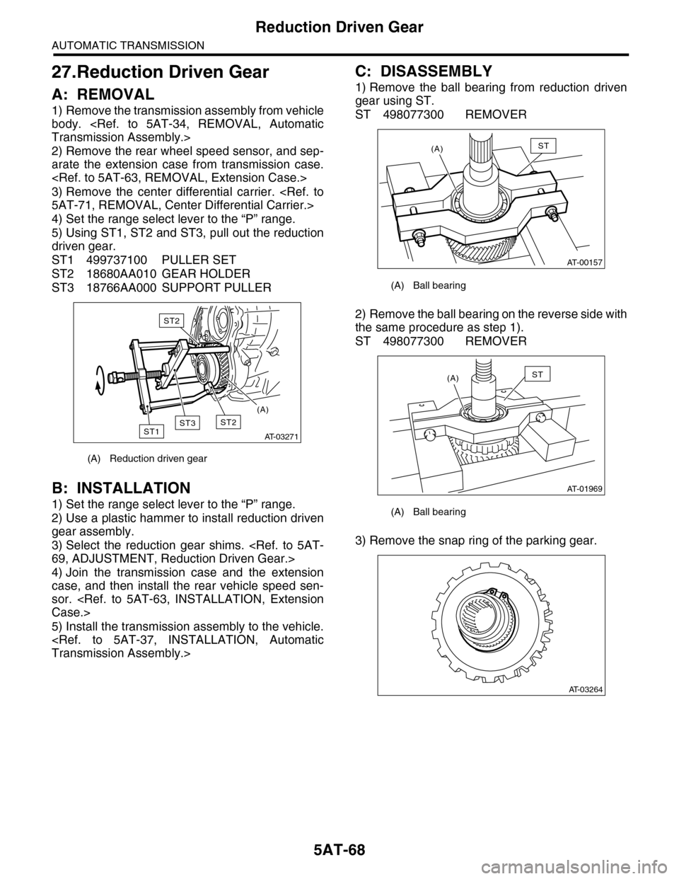
4) Set the range select lever to the “P” range.
5) Using ST1, ST2 and ST3, pull out the reduction
driven gear.
ST1 499737100 PULLER SET
ST2 18680AA010 GEAR HOLDER
ST3 18766AA000 SUPPORT PULLER
B: INSTALLATION
1) Set the range select lever to the “P” range.
2) Use a plastic hammer to install reduction driven
gear assembly.
3) Select the reduction gear shims.
4) Join the transmission case and the extension
case, and then install the rear vehicle speed sen-
sor.
5) Install the transmission assembly to the vehicle.
C: DISASSEMBLY
1) Remove the ball bearing from reduction driven
gear using ST.
ST 498077300 REMOVER
2) Remove the ball bearing on the reverse side with
the same procedure as step 1).
ST 498077300 REMOVER
3) Remove the snap ring of the parking gear.
(A) Reduction driven gear
AT-03271
ST2ST1
ST2
ST3
(A)
(A) Ball bearing
(A) Ball bearing
AT-00157
(A)ST
AT-01969
(A)ST
AT-03264
Page 2087 of 2453
5AT-71
Center Differential Carrier
AUTOMATIC TRANSMISSION
28.Center Differential Carrier
A: REMOVAL
1) Remove the transmission assembly from vehicle
body.
2) Remove the rear wheel speed sensor, and sep-
arate the extension case from transmission case.
3) Extract the rear drive shaft.
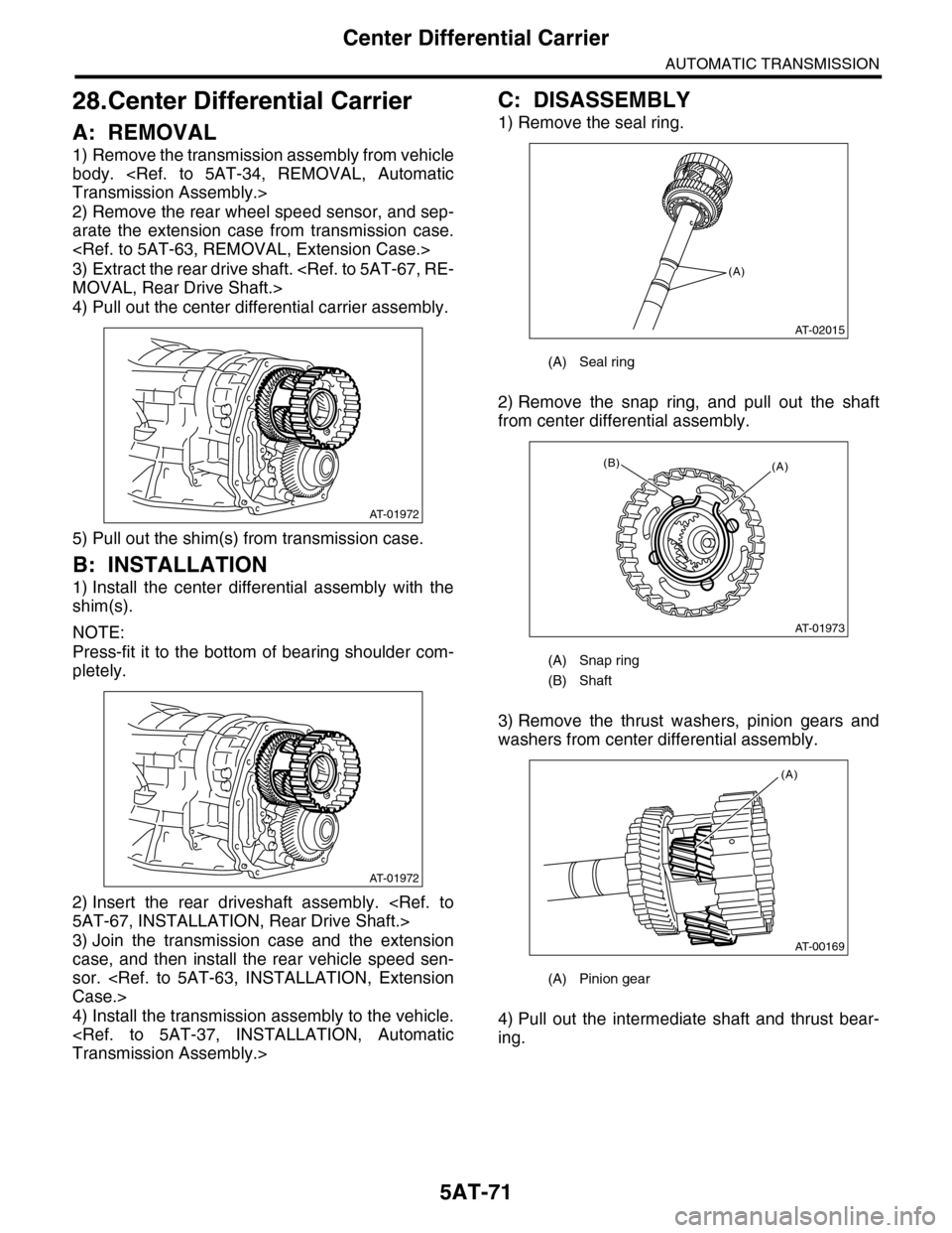
4) Pull out the center differential carrier assembly.
5) Pull out the shim(s) from transmission case.
B: INSTALLATION
1) Install the center differential assembly with the
shim(s).
NOTE:
Press-fit it to the bottom of bearing shoulder com-
pletely.
2) Insert the rear driveshaft assembly.
3) Join the transmission case and the extension
case, and then install the rear vehicle speed sen-
sor.
4) Install the transmission assembly to the vehicle.
C: DISASSEMBLY
1) Remove the seal ring.
2) Remove the snap ring, and pull out the shaft
from center differential assembly.
3) Remove the thrust washers, pinion gears and
washers from center differential assembly.
4) Pull out the intermediate shaft and thrust bear-
ing.
AT-01972
AT-01972
(A) Seal ring
(A) Snap ring
(B) Shaft
(A) Pinion gear
(A)
AT-02015
AT-01973
(A)(B)
AT-00169
(A)
Page 2088 of 2453
5AT-72
Center Differential Carrier
AUTOMATIC TRANSMISSION
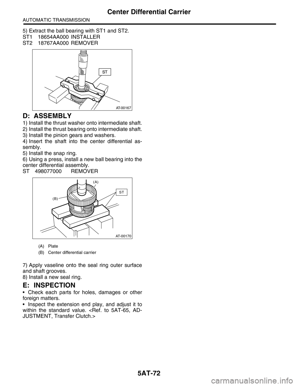
5) Extract the ball bearing with ST1 and ST2.
ST1 18654AA000 INSTALLER
ST2 18767AA000 REMOVER
D: ASSEMBLY
1) Install the thrust washer onto intermediate shaft.
2) Install the thrust bearing onto intermediate shaft.
3) Install the pinion gears and washers.
4) Insert the shaft into the center differential as-
sembly.
5) Install the snap ring.
6) Using a press, install a new ball bearing into the
center differential assembly.
ST 498077000 REMOVER
7) Apply vaseline onto the seal ring outer surface
and shaft grooves.
8) Install a new seal ring.
E: INSPECTION
•Check each parts for holes, damages or other
foreign matters.
•Inspect the extension end play, and adjust it to
within the standard value.
(A) Plate
(B) Center differential carrier
AT-00167
AT-00170
(A)
(B)
ST