Page 2105 of 2453
5AT-89
Front Differential Assembly
AUTOMATIC TRANSMISSION
2. SIDE RETAINER
NOTE:
Install the oil seal and O-ring of side retainer after
the adjustment of backlash and tooth contact.
1) Install the bearing outer race to side retainer.
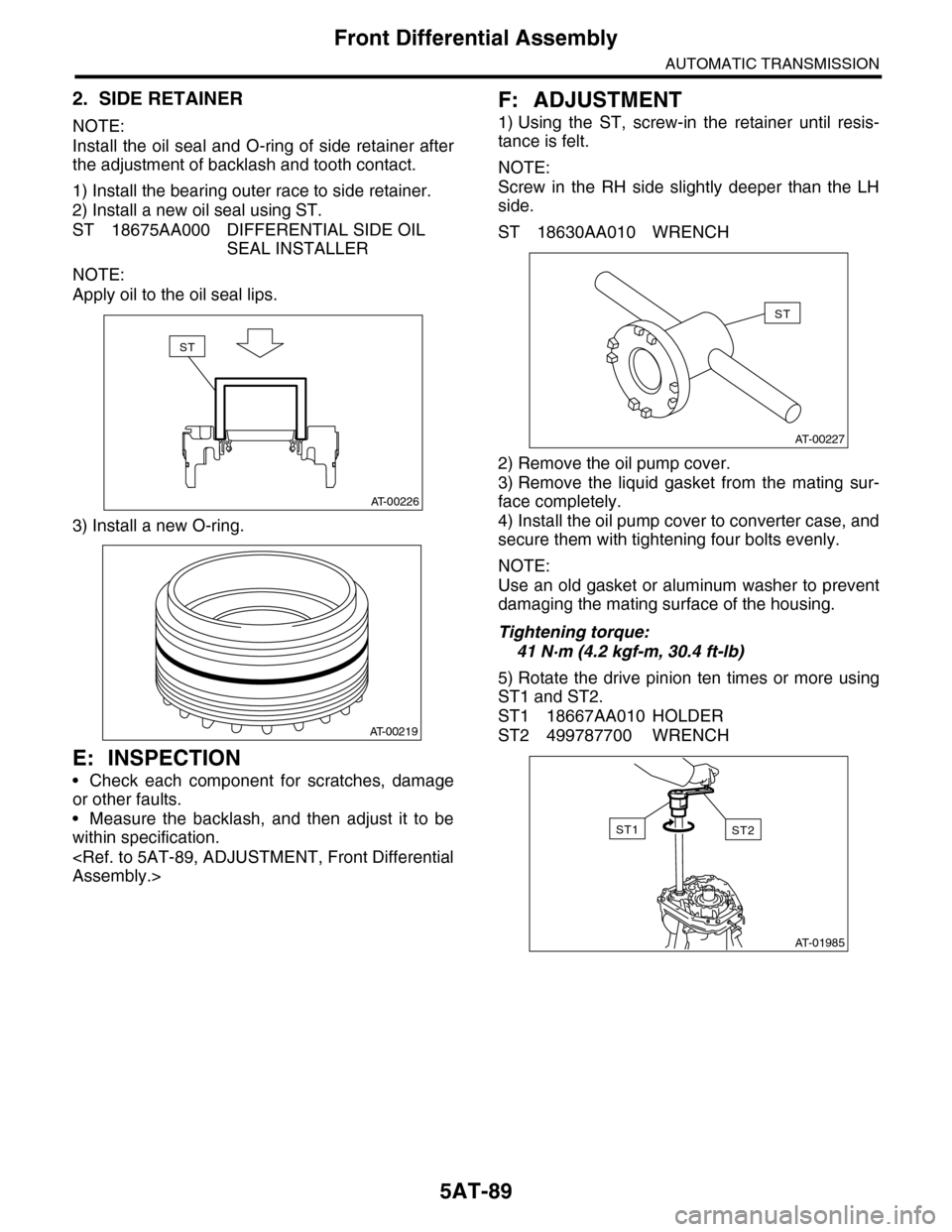
2) Install a new oil seal using ST.
ST 18675AA000 DIFFERENTIAL SIDE OIL
SEAL INSTALLER
NOTE:
Apply oil to the oil seal lips.
3) Install a new O-ring.
E: INSPECTION
•Check each component for scratches, damage
or other faults.
•Measure the backlash, and then adjust it to be
within specification.
Assembly.>
F: ADJUSTMENT
1) Using the ST, screw-in the retainer until resis-
tance is felt.
NOTE:
Screw in the RH side slightly deeper than the LH
side.
ST 18630AA010 WRENCH
2) Remove the oil pump cover.
3) Remove the liquid gasket from the mating sur-
face completely.
4) Install the oil pump cover to converter case, and
secure them with tightening four bolts evenly.
NOTE:
Use an old gasket or aluminum washer to prevent
damaging the mating surface of the housing.
Tightening torque:
41 N·m (4.2 kgf-m, 30.4 ft-lb)
5) Rotate the drive pinion ten times or more using
ST1 and ST2.
ST1 18667AA010 HOLDER
ST2 499787700 WRENCH
AT-00226
ST
AT-00219
AT-00227
ST
AT-01985
ST2ST1
Page 2106 of 2453
5AT-90
Front Differential Assembly
AUTOMATIC TRANSMISSION
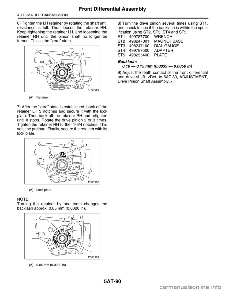
6) Tighten the LH retainer by rotating the shaft until
resistance is felt. Then loosen the retainer RH.
Keep tightening the retainer LH, and loosening the
retainer RH until the pinion shaft no longer be
turned. This is the “zero” state.
7) After the “zero” state is established, back off the
retainer LH 3 notches and secure it with the lock
plate. Then back off the retainer RH and retighten
until it stops. Rotate the drive pinion 2 or 3 times.
Tighten the retainer RH further 1-3/4 notches. This
sets the preload. Finally, secure the retainer with its
lock plate.
NOTE:
Turning the retainer by one tooth changes the
backlash approx. 0.05 mm (0.0020 in).
8) Turn the drive pinion several times using ST1,
and check to see if the backlash is within the spec-
ification using ST2, ST3, ST4 and ST5.
ST1 499787700 WRENCH
ST2 498247001 MAGNET BASE
ST3 498247100 DIAL GAUGE
ST4 499787500 ADAPTER
ST5 498255400 PLATE
Backlash:
0.10 — 0.15 mm (0.0039 — 0.0059 in)
9) Adjust the teeth contact of the front differential
and drive shaft.
Drive Pinion Shaft Assembly.>
(A) Retainer
(A) Lock plate
(A) 0.05 mm (0.0020 in)
AT-01986
(A)
AT-01988
(A)
AT-01989
(A)
Page 2107 of 2453
5AT-91
AT Main Case
AUTOMATIC TRANSMISSION
34.AT Main Case
A: REMOVAL
1) Remove the transmission assembly from vehicle
body.
Transmission Assembly.>
2) Pull out the torque converter assembly.
5AT-62, REMOVAL, Torque Converter Assembly.>
3) Remove the transmission harness connector
from stay.
4) Disconnect the air breather hose.
5) Remove the oil charge pipe.
REMOVAL, Oil Charge Pipe.>
6) Remove the ATF filter inlet and outlet pipes.
Hose.>
7) Remove the extension case.
REMOVAL, Extension Case.>
8) Remove the center differential carrier.
5AT-71, REMOVAL, Center Differential Carrier.>
9) Remove the reduction driven gear.
68, REMOVAL, Reduction Driven Gear.>
10) Separate the converter case from the transmis-
sion case.
Case.>
11) Remove the control valve body.
53, REMOVAL, Control Valve Body.>
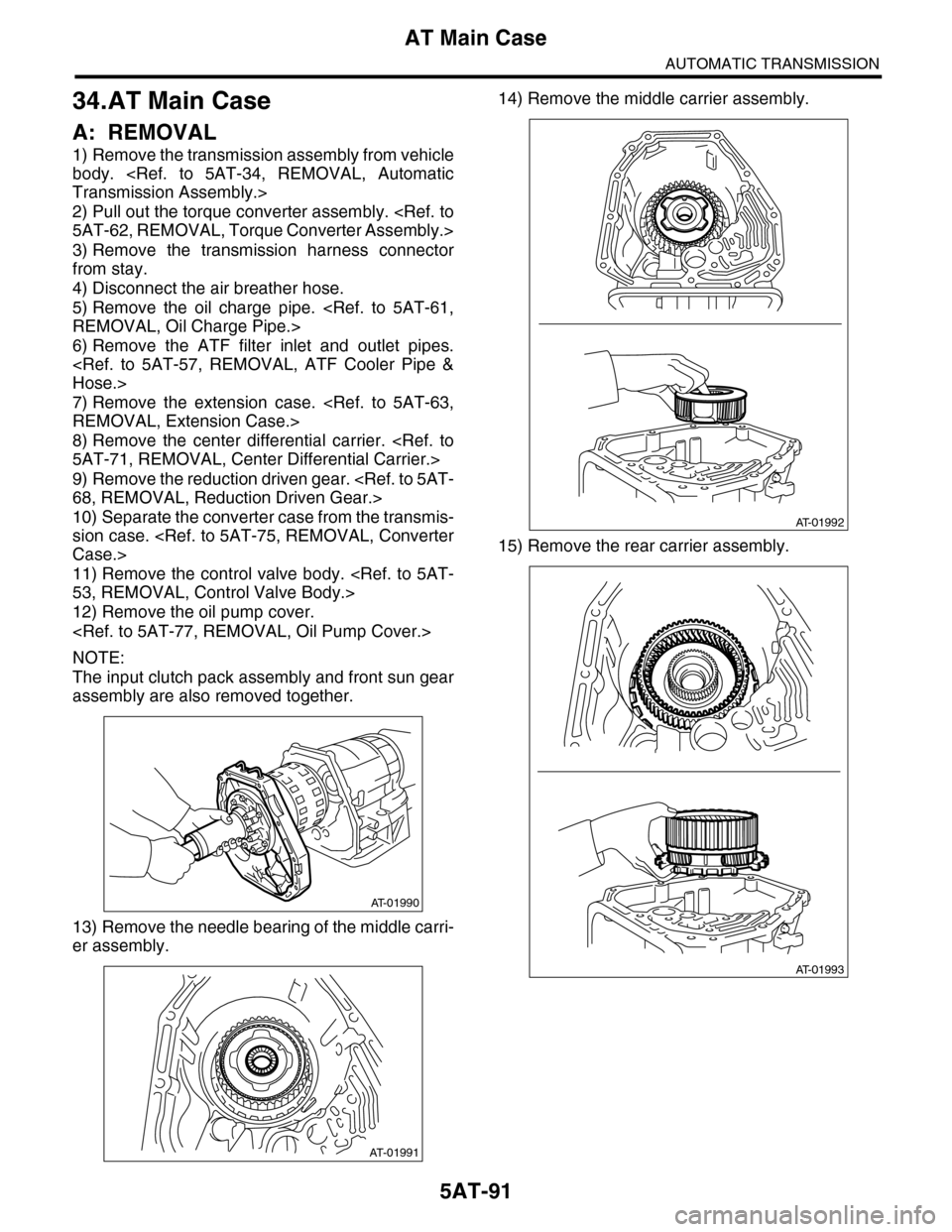
12) Remove the oil pump cover.
NOTE:
The input clutch pack assembly and front sun gear
assembly are also removed together.
13) Remove the needle bearing of the middle carri-
er assembly.
14) Remove the middle carrier assembly.
15) Remove the rear carrier assembly.
AT-01990
AT-01991
AT-01992
AT-01993
Page 2112 of 2453
5AT-96
AT Main Case
AUTOMATIC TRANSMISSION
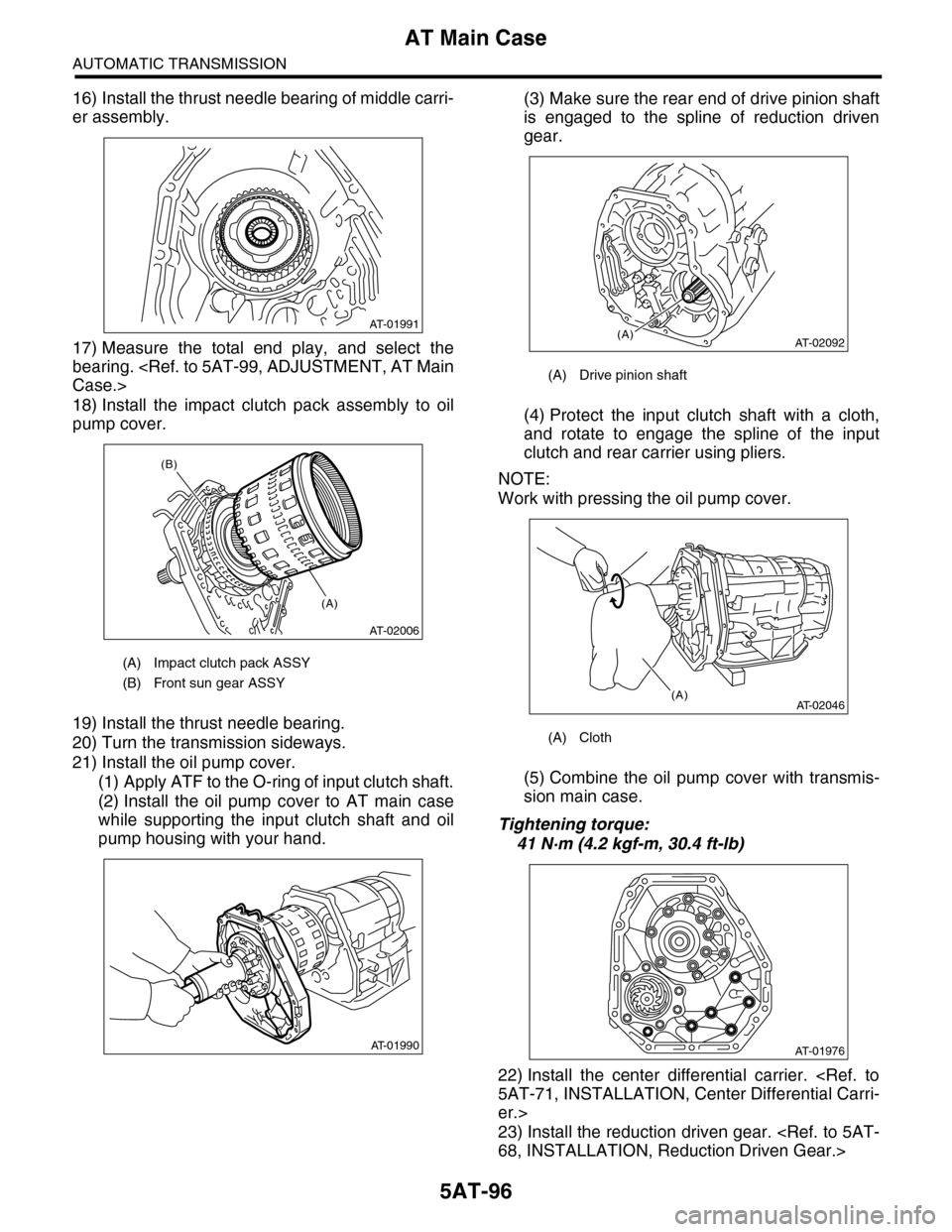
16) Install the thrust needle bearing of middle carri-
er assembly.
17) Measure the total end play, and select the
bearing.
Case.>
18) Install the impact clutch pack assembly to oil
pump cover.
19) Install the thrust needle bearing.
20) Turn the transmission sideways.
21) Install the oil pump cover.
(1) Apply ATF to the O-ring of input clutch shaft.
(2) Install the oil pump cover to AT main case
while supporting the input clutch shaft and oil
pump housing with your hand.
(3) Make sure the rear end of drive pinion shaft
is engaged to the spline of reduction driven
gear.
(4) Protect the input clutch shaft with a cloth,
and rotate to engage the spline of the input
clutch and rear carrier using pliers.
NOTE:
Work with pressing the oil pump cover.
(5) Combine the oil pump cover with transmis-
sion main case.
Tightening torque:
41 N·m (4.2 kgf-m, 30.4 ft-lb)
22) Install the center differential carrier.
5AT-71, INSTALLATION, Center Differential Carri-
er.>
23) Install the reduction driven gear.
68, INSTALLATION, Reduction Driven Gear.>
(A) Impact clutch pack ASSY
(B) Front sun gear ASSY
AT-01991
AT-02006
(A)
(B)
AT-01990
(A) Drive pinion shaft
(A) Cloth
AT-02092(A)
AT-02046(A)
AT-01976
Page 2122 of 2453
5AT(diag)-5
General Description
AUTOMATIC TRANSMISSION (DIAGNOSTICS)
3. General Description
A: CAUTION
•SRS AIRBAG SYSTEM
The airbag system wiring harness is routed near
the TCM.
CAUTION:
•All air bag system wiring harnesses and con-
nectors are colored yellow. Do not use an elec-
tric test equipment to check these circuits.
•Be careful not to damage the airbag system
wiring harness when performing diagnostics or
servicing the TCM.
•MEASUREMENT
When measuring the voltage and resistance of the
ECM, TCM or each sensor, use a tapered pin with
a diameter of less than 0.64 mm (0.025 in) in order
to avoid poor contact. Do not insert a pin of more
than 0.65 mm (0.026 in) diameter.
B: INSPECTION
1. BATTERY
Measure the battery voltage and specific gravity of
electrolyte.
Standard voltage: 12 V or more
Specific gravity: 1.260 or more
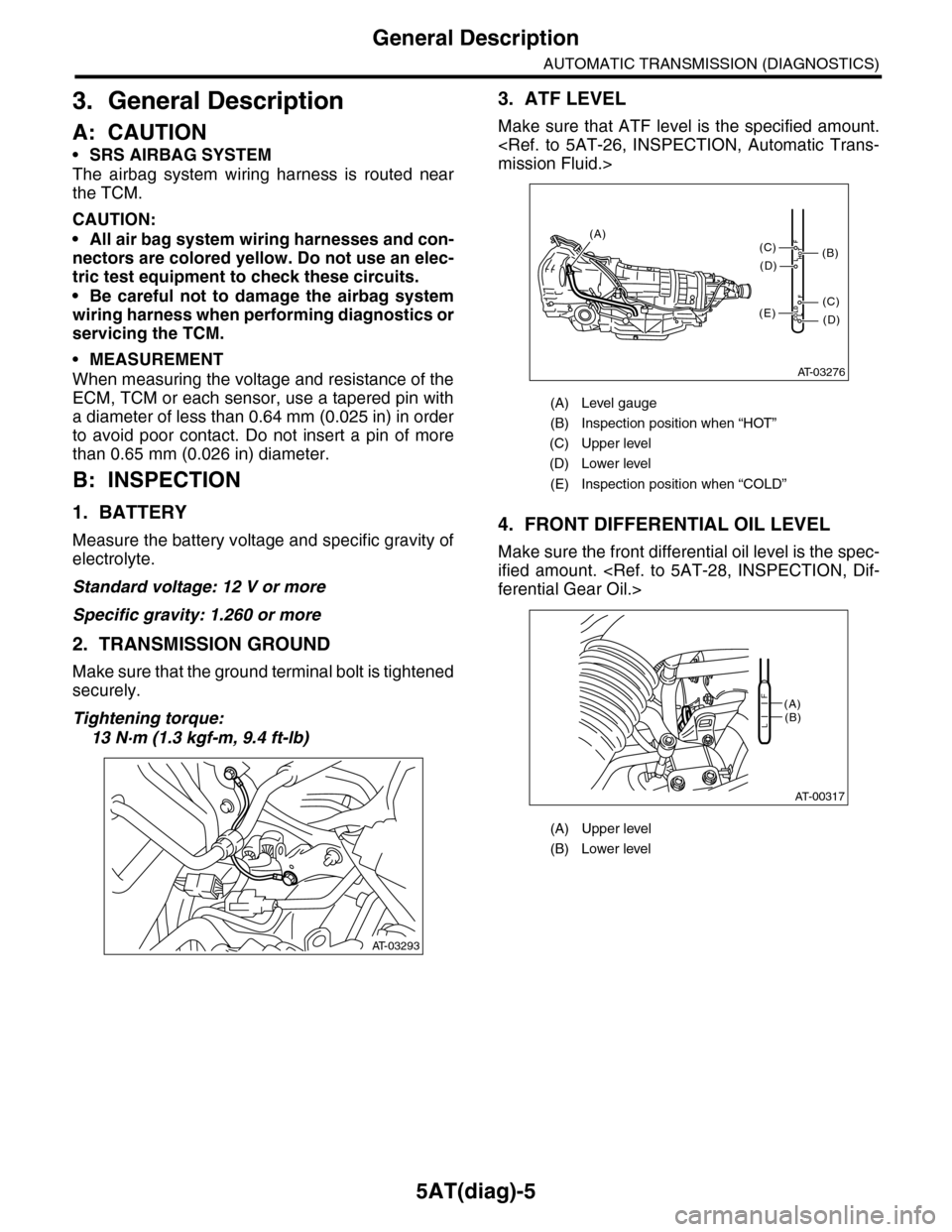
2. TRANSMISSION GROUND
Make sure that the ground terminal bolt is tightened
securely.
Tightening torque:
13 N·m (1.3 kgf-m, 9.4 ft-lb)
3. ATF LEVEL
Make sure that ATF level is the specified amount.
mission Fluid.>
4. FRONT DIFFERENTIAL OIL LEVEL
Make sure the front differential oil level is the spec-
ified amount.
ferential Gear Oil.>
AT-03293
(A) Level gauge
(B) Inspection position when “HOT”
(C) Upper level
(D) Lower level
(E) Inspection position when “COLD”
(A) Upper level
(B) Lower level
AT-03276
COLDLF
HOTLF
(C)
(D)
(C)
(D)
(E)
(B)
(A)
AT-00317
(A)(B)L
F
Page 2416 of 2453
WI-132
Combination Meter System
WIRING SYSTEM
WI-08134
METER-02METER-02
ECM
TPM
CONTROL M
ODULE
VDC CONTROL M
ODULE
OIL P
RESSURE SW
ITCH
GENERATOR
BRAKE FLU
ID LEV
EL SWITCH
AIRBAG WARNING LIGHT
HEADLIGHT RELAYAIRBAG CONTROLMODULE
ABS WARNING LIGHT
CHARGE WARNING LIGHTPARKING BRAKE/BRAKE FLUIDLEVEL WARNING LIGHT
VDC CONTROL M
ODULE
PARKING BRAKE SWITCH
REAR DIFFE
RENTIAL
PRESSURE SWITCH
SEA
T BELT W
ARNING LIG
HT
SEAT BELT S
WITCH
A3
IGNITION SWITCH (IG)
A4
REVERSECIRCUIT
OIL PRESSUREWARNING LIGHT
MALFUNCTION INDICATOR LIGHT
HI-BEAM INDICATOR LIGHT
TURN SIGNAL &HAZARD MODULE
TURN SIGNALINDICATOR LIGHT LHTURN SIGNALINDICATOR LIGHT RH
REVERSECIRCUIT
REVERSECIRCUIT
B
B3A14B1B12
METER-03A
BATTERY
B8B7B9B6B10B5B4B11
REAR DIFFERENTIAL OIL TEMPERATURE WARNING LIGHT
REVERSECIRCUIT
DIMMER SWITCH
TIRE INFLATION PRESSURE WARNING LIGHT
REVERSECIRCUIT
A10A7
Page 2432 of 2453
WI-148
Rear Differential Oil Temperature Warning Light System
WIRING SYSTEM
53.Rear Differential Oil Temperature Warning Light System
A: WIRING DIAGRAM
WI-08322
D/T-01D/T-01
48
i53
R98
R15
R60
1
Y
Y
YB
B
B
Y
Y
YBYBY
REARDIFFERENTIALOIL TEMPERATUREWARNING LIGHT
R234R277
REAR DIFFERENTIAL OILTEMPERATURE SWITCH
REAR DIFFERENTIAL
STAYGROUND
i10
19 20 2115 16 17 182223242526272829301234568910 11 12 13 147
A:R60
12
10115634897131412
123 8910411 12 13 14 15 16567171819202122
i53(BLUE)
123456789101112
i126(BLACK)
i127(BLACK)
: TERMINAL NO. OPTIONAL ARRANGEMENT BETWEEN 5 AND 6
1*
: TERMINAL NO. OPTIONAL ARRANGEMENT AMONG 7, 8 AND 9
2*
: TERMINAL NO. OPTIONAL ARRANGEMENT AMONG 10, 11 AND 12
3*COMBINATION METER
A: i10
I/F
I/F
MICRO COMPUTERDRIVER
A15A7A16
A3A4
BrW
BrW
BrW
BrW
JOINTCONNECTOR
i126
i127
3*
2*2*
BY
REF. TO GROUNDCIRCUIT [GND-05]
B
REF. TO GROUNDCIRCUIT [GND-05]
FB-36F/B FUSE NO. 5(IG)
TO POWER SUPPLY CIRCUIT
Page 2445 of 2453
WI-161
Rear Wiring Harness
WIRING SYSTEM
60.Rear Wiring Harness
A: LOCATION
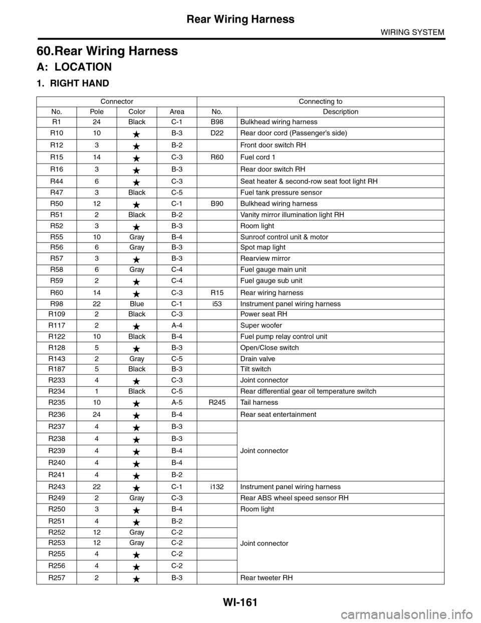
1. RIGHT HAND
Connector Connecting to
No. Pole Color Area No. Description
R1 24 Black C-1 B98 Bulkhead wiring harness
R10 10 B-3 D22 Rear door cord (Passenger’s side)
R12 3 B-2 Front door switch RH
R15 14 C-3 R60 Fuel cord 1
R16 3 B-3 Rear door switch RH
R44 6 C-3 Seat heater & second-row seat foot light RH
R47 3 Black C-5 Fuel tank pressure sensor
R50 12 C-1 B90 Bulkhead wiring harness
R51 2 Black B-2 Vanity mirror illumination light RH
R52 3 B-3 Room light
R55 10 Gray B-4 Sunroof control unit & motor
R56 6 Gray B-3 Spot map light
R57 3 B-3 Rearview mirror
R58 6 Gray C-4 Fuel gauge main unit
R59 2 C-4 Fuel gauge sub unit
R60 14 C-3 R15 Rear wiring harness
R98 22 Blue C-1 i53 Instrument panel wiring harness
R109 2 Black C-3 Power seat RH
R117 2 A-4 Super woofer
R122 10 Black B-4 Fuel pump relay control unit
R128 5 B-3 Open/Close switch
R143 2 Gray C-5 Drain valve
R187 5 Black B-3 Tilt switch
R233 4 C-3 Joint connector
R234 1 Black C-5 Rear differential gear oil temperature switch
R235 10 A-5 R245 Tail harness
R236 24 B-4 Rear seat entertainment
R237 4 B-3
Joint connector
R238 4 B-3
R239 4 B-4
R240 4 B-4
R241 4 B-2
R243 22 C-1 i132 Instrument panel wiring harness
R249 2 Gray C-3 Rear ABS wheel speed sensor RH
R250 3 B-4 Room light
R251 4 B-2
Joint connector
R252 12 Gray C-2
R253 12 Gray C-2
R255 4 C-2
R256 4 C-2
R257 2 B-3 Rear tweeter RH