Page 845 of 2453

DS-28
Rear Drive Shaft
DRIVE SHAFT SYSTEM
8. Rear Drive Shaft
A: REMOVAL
1) Disconnect the ground cable from the battery.
2) Lift-up the vehicle, and then remove the rear
wheels.
3) Lift the crimped section of axle nut.
4) While applying the parking brake, remove the
axle nut using a socket wrench.
CAUTION:
Remove the wheel before loosening the axle
nut. Failure to follow this rule may damage the
wheel bearings.
5) Remove the rear differential assembly.
VA-type
type).>
6) Remove the axle nut and rear drive shaft. If it is
hard to remove, use ST1 and ST2.
ST1 926470000 AXLE SHAFT PULLER
ST2 28099PA110 AXLE SHAFT PULLER
PLATE
CAUTION:
•Do not hammer drive shaft when removing.
•Do not damage the oil seal and magnetic en-
coder.
B: INSTALLATION
1) Insert the EBJ into hub splines.
CAUTION:
•Be careful not to damage the magnetic en-
coder.
•Do not get closer the tool which charged
magnetism to magnetic encoder.
2) Draw the rear drive shaft into specified position.
CAUTION:
Do not hammer drive shaft when installing it.
3) Tighten the axle nut temporarily.
4) Install the rear differential assembly.
VA-type
(VA–type).>
5) While applying the parking brake and depress-
ing the brake pedal, tighten a new axle nut (olive
color) to the specified torque and lock it securely.
Tightening torque:
240 N·m (24.5 kgf-m, 177 ft-lb)
CAUTION:
•Install the wheel after installation of axle nut.
Failure to follow this rule may damage the
wheel bearing.
•Be sure to tighten the axle nut to specified
torque. Do not overtighten it as this may dam-
age the wheel bearing.
6) Lock the axle nut securely.
DS-00038
DS-00122
ST2ST1
(1) Magnetic encoder
(2) Rear hub unit bearing
DS-00251
(2)
(1)
DS-00048
Page 939 of 2453
RS-6
General Description
REAR SUSPENSION
2. GENERAL TOOL
28099PA090 OIL SEAL PROTEC-
TOR
•Used for installing the rear drive shaft to the
rear differential.
•For oil seal protection
TOOL NAME REMARKS
Alignment tester Used for measuring wheel alignment.
To e – i n g a u g e U s e d f o r t o e – i n m e a s u r e m e n t .
Jack Used for removing and installing suspension.
Bearing puller Used for removing bushings.
Coil spring compressor Used for disassembling and assembling shock absorber.
ILLUSTRATION TOOL NUMBER DESCRIPTION REMARKS
ST28099PA090
Page 990 of 2453
TC-5
Oil Seal
TRANSFER CASE
4. Oil Seal
A: NOTE
For inspection, refer to the 5AT section.
to 5AT-45, Differential Side Retainer Oil Seal.>
Page 991 of 2453
TC-6
Center Differential Carrier
TRANSFER CASE
5. Center Differential Carrier
A: NOTE
For removal, installation and inspection, refer to
“5AT” section.
Page 1986 of 2453

PM-3
Schedule
PERIODIC MAINTENANCE SERVICES
2. Schedule
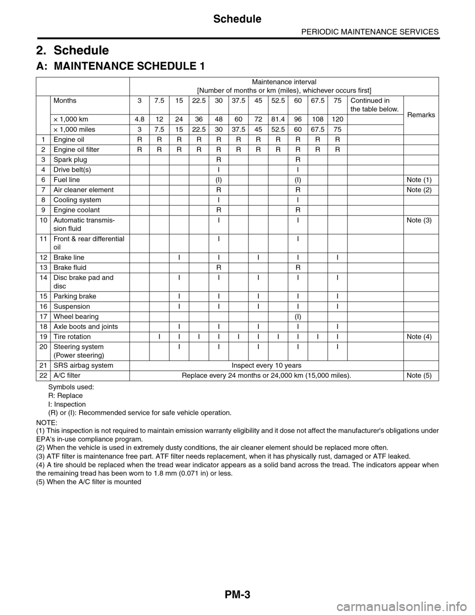
A: MAINTENANCE SCHEDULE 1
Symbols used:
R: Replace
I: Inspection
(R) or (I): Recommended service for safe vehicle operation.
NOTE:(1) This inspection is not required to maintain emission warranty eligibility and it dose not affect the manufacturer's obligations under
EPA's in-use compliance program.
(2) When the vehicle is used in extremely dusty conditions, the air cleaner element should be replaced more often.
(3) ATF filter is maintenance free part. ATF filter needs replacement, when it has physically rust, damaged or ATF leaked.
(4) A tire should be replaced when the tread wear indicator appears as a solid band across the tread. The indicators appear when
the remaining tread has been worn to 1.8 mm (0.071 in) or less.
(5) When the A/C filter is mounted
Maintenance interval
[Number of months or km (miles), whichever occurs first]
Months 3 7.51522.53037.54552.56067.575Continued in
the table below.Remarks× 1,000 km 4.8 12 24 36 48 60 72 81.4 96 108 120
× 1,000 miles 3 7.5 15 22.5 30 37.5 45 52.5 60 67.5 75
1Engine oil R R R R R R R R R R R
2Engine oil filter R R R R R R R R R R R
3Spark plug R R
4Drive belt(s) I I
6Fuel line (I) (I) Note (1)
7Air cleaner element R R Note (2)
8Cooling system I I
9Engine coolant R R
10 Automatic transmis-
sion fluid
I I Note (3)
11 Front & rear differential
oil
I I
12 Brake line I I I I I
13 Brake fluid R R
14 Disc brake pad and
disc
I I I I I
15 Parking brake I I I I I
16 Suspension I I I I I
17 Wheel bearing (I)
18 Axle boots and joints I I I I I
19 Tire rotation I I I I I I I I I I Note (4)
20 Steering system
(Power steering)
I I I I I
21 SRS airbag system Inspect every 10 years
22 A/C filter Replace every 24 months or 24,000 km (15,000 miles). Note (5)
Page 1987 of 2453

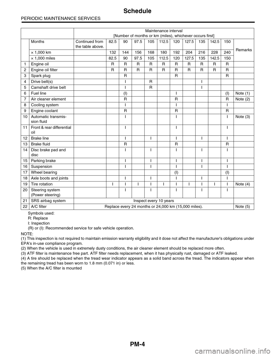
PM-4
Schedule
PERIODIC MAINTENANCE SERVICES
Symbols used:
R: Replace
I: Inspection
(R) or (I): Recommended service for safe vehicle operation.
NOTE:(1) This inspection is not required to maintain emission warranty eligibility and it dose not affect the manufacturer's obligations under
EPA's in-use compliance program.
(2) When the vehicle is used in extremely dusty conditions, the air cleaner element should be replaced more often.
(3) ATF filter is maintenance free part. ATF filter needs replacement, when it has physically rust, damaged or ATF leaked.
(4) A tire should be replaced when the tread wear indicator appears as a solid band across the tread. The indicators appear when
the remaining tread has been worn to 1.8 mm (0.071 in) or less.
(5) When the A/C filter is mounted
Maintenance interval
[Number of months or km (miles), whichever occurs first]
Months Continued from
the table above.
82.5 90 97.5 105112.5120127.5135142.5150
Remarks× 1,000 km 132 144 156 168 180 192 204 216 228 240
× 1,000 miles 82.5 90 97.5 105112.5120127.5135142.5150
1Engine oil R R R R R R R R R R
2Engine oil filter R R R R R R R R R R
3Spark plug R R R
4Drive belt(s) I R I
5Camshaft drive belt I R I
6Fuel line (I) I (I) Note (1)
7Air cleaner element R R R Note (2)
8Cooling system I I I
9Engine coolant R R R
10 Automatic transmis-
sion fluid
I I INote (3)
11 Front & rear differential
oil
I I I
12 Brake line I I I I I
13 Brake fluid R R R
14 Disc brake pad and
disc
I I I I I
15 Parking brake I I I I I
16 Suspension I I I I I
17 Wheel bearing (I) (I)
18 Axle boots and joints I I I I I
19 Tire rotation I I I I I I I I I I Note (4)
20 Steering system
(Power steering)
I I I I I
21 SRS airbag system Inspect every 10 years
22 A/C filter Replace every 24 months or 24,000 km (15,000 miles). Note (5)
Page 1988 of 2453
PM-5
Schedule
PERIODIC MAINTENANCE SERVICES
B: MAINTENANCE SCHEDULE 2
ItemMaintenance
interval
Repeat short
distance drive
Repeat
rough/muddy
road drive
Extremely
cold weather
area
Salt or other
corrosive
used or
coastal area
High humid-
ity or moun-
tain area
Repeat tow-
ing trailer
Engine oil 3.75 months R R R
6,000 km
3,750 miles
Engine oil filter 3.75 months R R R
6,000 km
3,750 miles
Fuel line 7.5 months I
12,000 km
7,500 miles
Automatic trans-
mission fluid
15 months R
24,000 km
15,000 miles
Fr o nt & r ea r
differential oil
15 months R
24,000 km
15,000 miles
Brake line 7.5 months I
12,000 km
7,500 miles
Brake fluid 15 months R
24,000 km
15,000 miles
Disc brake pad
and disc
15 months I I I I
24,000 km
15,000 miles
Par king brake 15 months I I I I
24,000 km
15,000 miles
Suspension 7.5 months I I I
12,000 km
7,500 miles
Axle boots and
joints
7.5 months I I I I I
12,000 km
7,500 miles
Steering system
(Power steering)
7.5 months I I I
12,000 km
7,500 miles
Page 2001 of 2453

PM-18
Front & Rear Differential Oil
PERIODIC MAINTENANCE SERVICES
12.Front & Rear Differential Oil
A: REPLACEMENT
1. FRONT DIFFERENTIAL
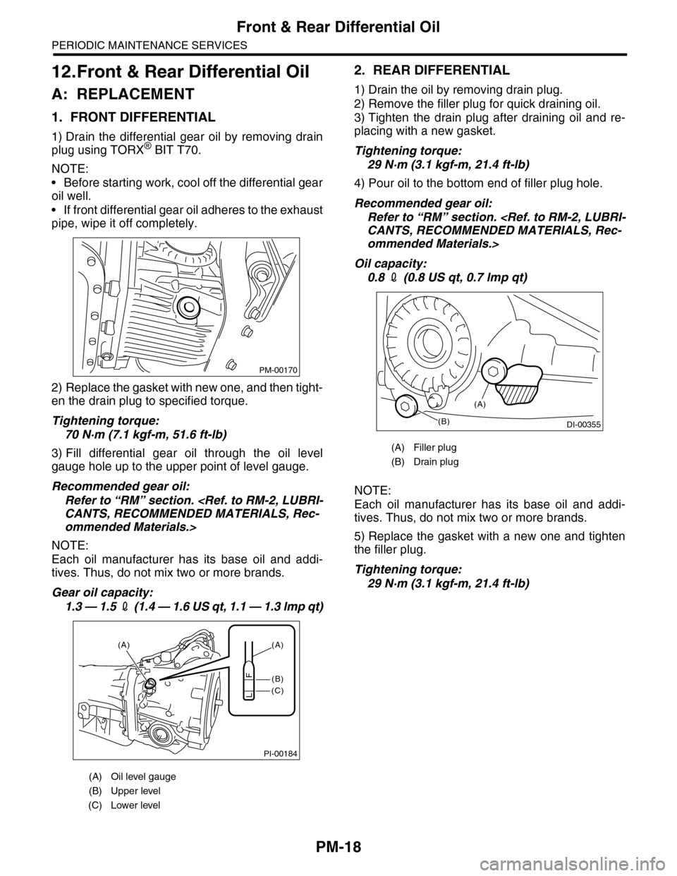
1) Drain the differential gear oil by removing drain
plug using TORX® BIT T70.
NOTE:
•Before starting work, cool off the differential gear
oil well.
•If front differential gear oil adheres to the exhaust
pipe, wipe it off completely.
2) Replace the gasket with new one, and then tight-
en the drain plug to specified torque.
Tightening torque:
70 N·m (7.1 kgf-m, 51.6 ft-lb)
3) Fill differential gear oil through the oil level
gauge hole up to the upper point of level gauge.
Recommended gear oil:
Refer to “RM” section.
CANTS, RECOMMENDED MATERIALS, Rec-
ommended Materials.>
NOTE:
Each oil manufacturer has its base oil and addi-
tives. Thus, do not mix two or more brands.
Gear oil capacity:
1.3 — 1.5 2 (1 . 4 — 1 .6 U S q t , 1 . 1 — 1 .3 lmp q t)
2. REAR DIFFERENTIAL
1) Drain the oil by removing drain plug.
2) Remove the filler plug for quick draining oil.
3) Tighten the drain plug after draining oil and re-
placing with a new gasket.
Tightening torque:
29 N·m (3.1 kgf-m, 21.4 ft-lb)
4) Pour oil to the bottom end of filler plug hole.
Recommended gear oil:
Refer to “RM” section.
CANTS, RECOMMENDED MATERIALS, Rec-
ommended Materials.>
Oil capacity:
0.8 2 (0.8 US qt, 0.7 lmp qt)
NOTE:
Each oil manufacturer has its base oil and addi-
tives. Thus, do not mix two or more brands.
5) Replace the gasket with a new one and tighten
the filler plug.
Tightening torque:
29 N·m (3.1 kgf-m, 21.4 ft-lb)
(A) Oil level gauge
(B) Upper level
(C) Lower level
PM-00170
PI-00184
(A)
(C)
(B)
(A)
F
L
(A) Filler plug
(B) Drain plug
(B)DI-00355
(A)