2009 SUBARU TRIBECA Intake
[x] Cancel search: IntakePage 1308 of 2453
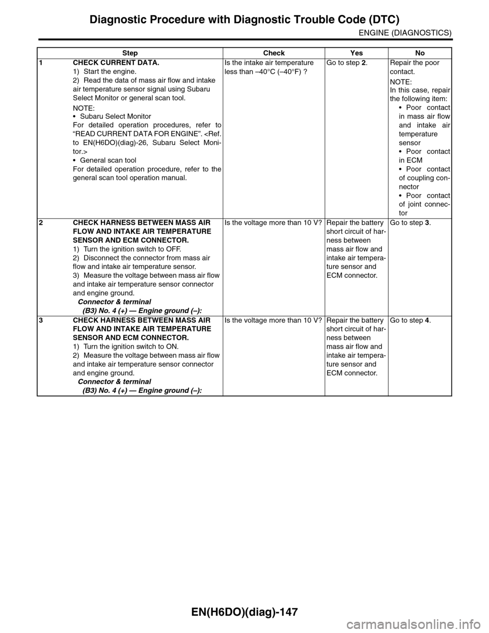
EN(H6DO)(diag)-147
Diagnostic Procedure with Diagnostic Trouble Code (DTC)
ENGINE (DIAGNOSTICS)
Step Check Yes No
1CHECK CURRENT DATA.
1) Start the engine.
2) Read the data of mass air flow and intake
air temperature sensor signal using Subaru
Select Monitor or general scan tool.
NOTE:
•Subaru Select Monitor
For detailed operation procedures, refer to
“READ CURRENT DATA FOR ENGINE”.
tor.>
•General scan tool
For detailed operation procedure, refer to the
general scan tool operation manual.
Is the intake air temperature
less than –40°C (–40°F) ?
Go to step 2.Repair the poor
contact.
NOTE:
In this case, repair
the following item:
•Poor contact
in mass air flow
and intake air
temperature
sensor
•Poor contact
in ECM
•Poor contact
of coupling con-
nector
•Poor contact
of joint connec-
tor
2CHECK HARNESS BETWEEN MASS AIR
FLOW AND INTAKE AIR TEMPERATURE
SENSOR AND ECM CONNECTOR.
1) Turn the ignition switch to OFF.
2) Disconnect the connector from mass air
flow and intake air temperature sensor.
3) Measure the voltage between mass air flow
and intake air temperature sensor connector
and engine ground.
Connector & terminal
(B3) No. 4 (+) — Engine ground (–):
Is the voltage more than 10 V? Repair the battery
short circuit of har-
ness between
mass air flow and
intake air tempera-
ture sensor and
ECM connector.
Go to step 3.
3CHECK HARNESS BETWEEN MASS AIR
FLOW AND INTAKE AIR TEMPERATURE
SENSOR AND ECM CONNECTOR.
1) Turn the ignition switch to ON.
2) Measure the voltage between mass air flow
and intake air temperature sensor connector
and engine ground.
Connector & terminal
(B3) No. 4 (+) — Engine ground (–):
Is the voltage more than 10 V? Repair the battery
short circuit of har-
ness between
mass air flow and
intake air tempera-
ture sensor and
ECM connector.
Go to step 4.
Page 1309 of 2453
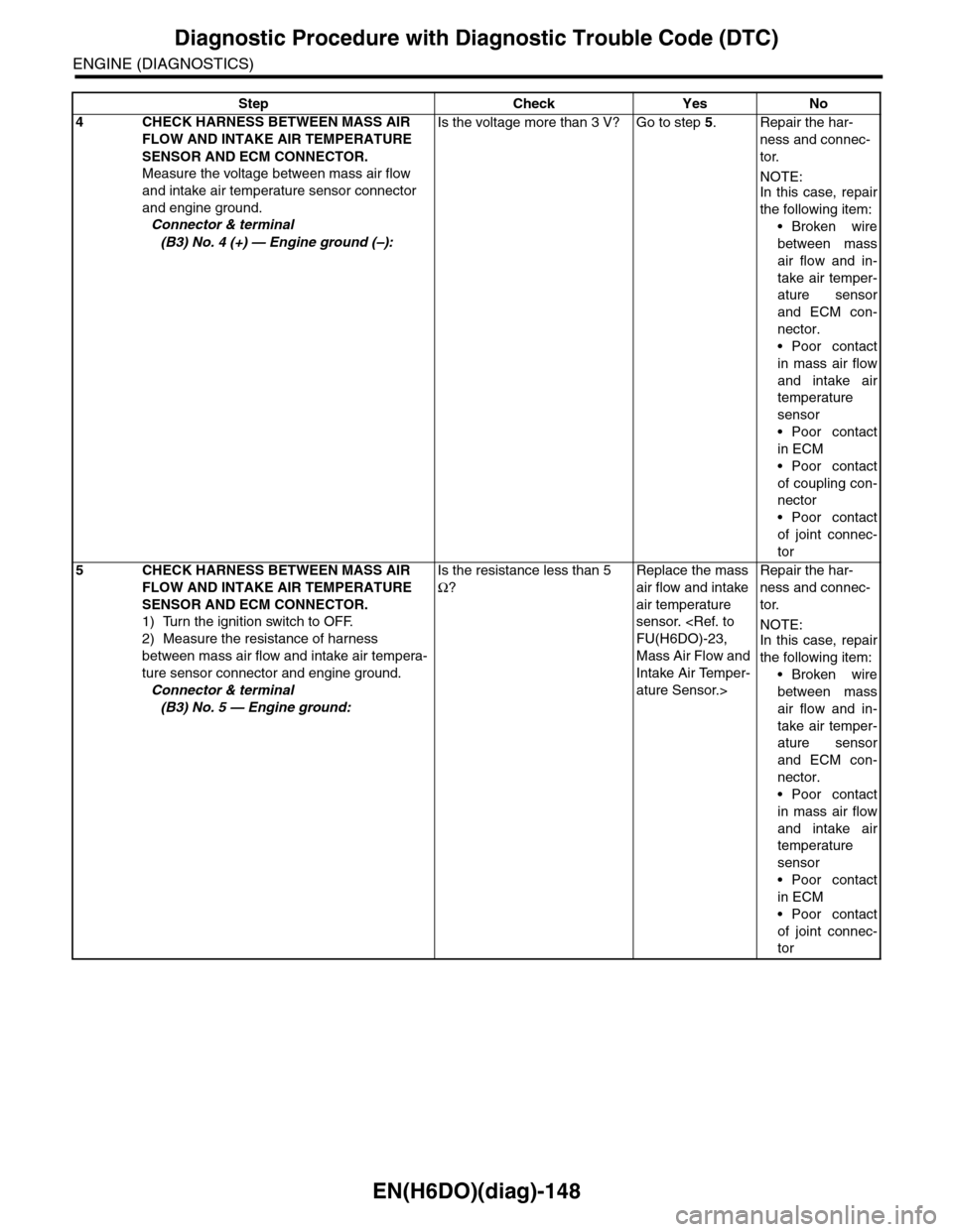
EN(H6DO)(diag)-148
Diagnostic Procedure with Diagnostic Trouble Code (DTC)
ENGINE (DIAGNOSTICS)
4CHECK HARNESS BETWEEN MASS AIR
FLOW AND INTAKE AIR TEMPERATURE
SENSOR AND ECM CONNECTOR.
Measure the voltage between mass air flow
and intake air temperature sensor connector
and engine ground.
Connector & terminal
(B3) No. 4 (+) — Engine ground (–):
Is the voltage more than 3 V? Go to step 5.Repair the har-
ness and connec-
tor.
NOTE:In this case, repair
the following item:
•Broken wire
between mass
air flow and in-
take air temper-
ature sensor
and ECM con-
nector.
•Poor contact
in mass air flow
and intake air
temperature
sensor
•Poor contact
in ECM
•Poor contact
of coupling con-
nector
•Poor contact
of joint connec-
tor
5CHECK HARNESS BETWEEN MASS AIR
FLOW AND INTAKE AIR TEMPERATURE
SENSOR AND ECM CONNECTOR.
1) Turn the ignition switch to OFF.
2) Measure the resistance of harness
between mass air flow and intake air tempera-
ture sensor connector and engine ground.
Connector & terminal
(B3) No. 5 — Engine ground:
Is the resistance less than 5
Ω?
Replace the mass
air flow and intake
air temperature
sensor.
Mass Air Flow and
Intake Air Temper-
ature Sensor.>
Repair the har-
ness and connec-
tor.
NOTE:In this case, repair
the following item:
•Broken wire
between mass
air flow and in-
take air temper-
ature sensor
and ECM con-
nector.
•Poor contact
in mass air flow
and intake air
temperature
sensor
•Poor contact
in ECM
•Poor contact
of joint connec-
tor
Step Check Yes No
Page 1379 of 2453
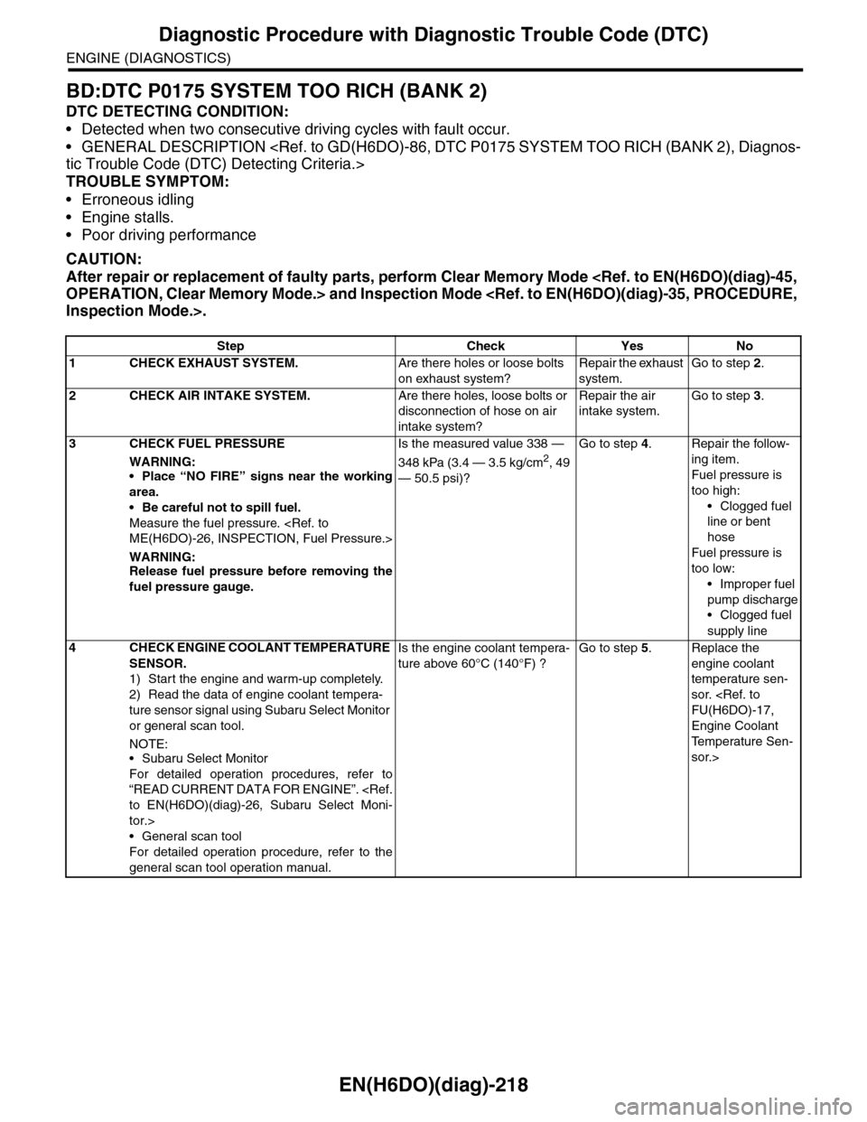
EN(H6DO)(diag)-218
Diagnostic Procedure with Diagnostic Trouble Code (DTC)
ENGINE (DIAGNOSTICS)
BD:DTC P0175 SYSTEM TOO RICH (BANK 2)
DTC DETECTING CONDITION:
•Detected when two consecutive driving cycles with fault occur.
•GENERAL DESCRIPTION
TROUBLE SYMPTOM:
•Erroneous idling
•Engine stalls.
•Poor driving performance
CAUTION:
After repair or replacement of faulty parts, perform Clear Memory Mode
Step Check Yes No
1 CHECK EXHAUST SYSTEM.Are there holes or loose bolts
on exhaust system?
Repair the exhaust
system.
Go to step 2.
2CHECK AIR INTAKE SYSTEM.Are there holes, loose bolts or
disconnection of hose on air
intake system?
Repair the air
intake system.
Go to step 3.
3CHECK FUEL PRESSURE
WARNING:
•Place “NO FIRE” signs near the working
area.
•Be careful not to spill fuel.
Measure the fuel pressure.
WARNING:Release fuel pressure before removing the
fuel pressure gauge.
Is the measured value 338 —
348 kPa (3.4 — 3.5 kg/cm2, 49
— 50.5 psi)?
Go to step 4.Repair the follow-
ing item.
Fuel pressure is
too high:
•Clogged fuel
line or bent
hose
Fuel pressure is
too low:
•Improper fuel
pump discharge
•Clogged fuel
supply line
4CHECK ENGINE COOLANT TEMPERATURE
SENSOR.
1) Start the engine and warm-up completely.
2) Read the data of engine coolant tempera-
ture sensor signal using Subaru Select Monitor
or general scan tool.
NOTE:•Subaru Select Monitor
For detailed operation procedures, refer to
“READ CURRENT DATA FOR ENGINE”.
tor.>
•General scan tool
For detailed operation procedure, refer to the
general scan tool operation manual.
Is the engine coolant tempera-
ture above 60°C (140°F) ?
Go to step 5.Replace the
engine coolant
temperature sen-
sor.
Engine Coolant
Te m p e r a t u r e S e n -
sor.>
Page 1380 of 2453
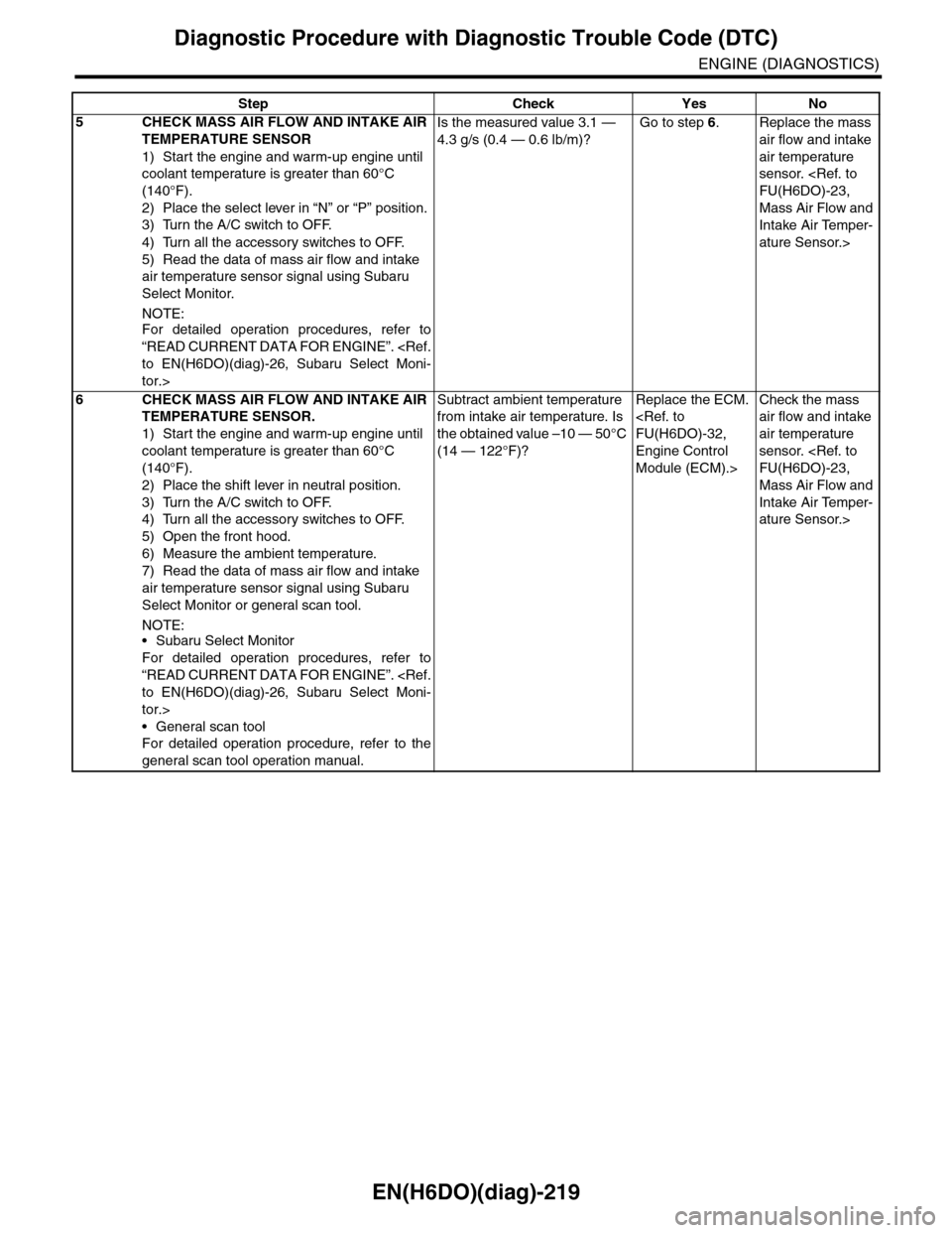
EN(H6DO)(diag)-219
Diagnostic Procedure with Diagnostic Trouble Code (DTC)
ENGINE (DIAGNOSTICS)
5CHECK MASS AIR FLOW AND INTAKE AIR
TEMPERATURE SENSOR
1) Start the engine and warm-up engine until
coolant temperature is greater than 60°C
(140°F).
2) Place the select lever in “N” or “P” position.
3) Turn the A/C switch to OFF.
4) Turn all the accessory switches to OFF.
5) Read the data of mass air flow and intake
air temperature sensor signal using Subaru
Select Monitor.
NOTE:
For detailed operation procedures, refer to
“READ CURRENT DATA FOR ENGINE”.
tor.>
Is the measured value 3.1 —
4.3 g/s (0.4 — 0.6 lb/m)?
Go to step 6.Replace the mass
air flow and intake
air temperature
sensor.
Mass Air Flow and
Intake Air Temper-
ature Sensor.>
6CHECK MASS AIR FLOW AND INTAKE AIR
TEMPERATURE SENSOR.
1) Start the engine and warm-up engine until
coolant temperature is greater than 60°C
(140°F).
2) Place the shift lever in neutral position.
3) Turn the A/C switch to OFF.
4) Turn all the accessory switches to OFF.
5) Open the front hood.
6) Measure the ambient temperature.
7) Read the data of mass air flow and intake
air temperature sensor signal using Subaru
Select Monitor or general scan tool.
NOTE:•Subaru Select Monitor
For detailed operation procedures, refer to
“READ CURRENT DATA FOR ENGINE”.
tor.>
•General scan tool
For detailed operation procedure, refer to the
general scan tool operation manual.
Subtract ambient temperature
from intake air temperature. Is
the obtained value –10 — 50°C
(14 — 122°F)?
Replace the ECM.
Engine Control
Module (ECM).>
Check the mass
air flow and intake
air temperature
sensor.
Mass Air Flow and
Intake Air Temper-
ature Sensor.>
Step Check Yes No
Page 1408 of 2453
EN(H6DO)(diag)-247
Diagnostic Procedure with Diagnostic Trouble Code (DTC)
ENGINE (DIAGNOSTICS)
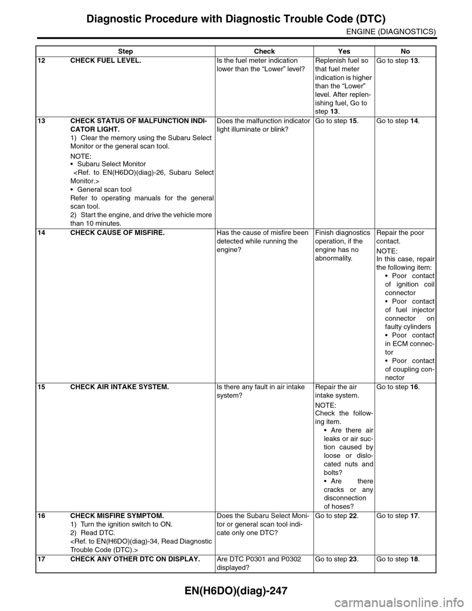
12 CHECK FUEL LEVEL.Is the fuel meter indication
lower than the “Lower” level?
Replenish fuel so
that fuel meter
indication is higher
than the “Lower”
level. After replen-
ishing fuel, Go to
step 13.
Go to step 13.
13 CHECK STATUS OF MALFUNCTION INDI-
CATOR LIGHT.
1) Clear the memory using the Subaru Select
Monitor or the general scan tool.
NOTE:•Subaru Select Monitor
•General scan tool
Refer to operating manuals for the general
scan tool.
2) Start the engine, and drive the vehicle more
than 10 minutes.
Does the malfunction indicator
light illuminate or blink?
Go to step 15.Go to step 14.
14 CHECK CAUSE OF MISFIRE.Has the cause of misfire been
detected while running the
engine?
Finish diagnostics
operation, if the
engine has no
abnormality.
Repair the poor
contact.
NOTE:In this case, repair
the following item:
•Poor contact
of ignition coil
connector
•Poor contact
of fuel injector
connector on
faulty cylinders
•Poor contact
in ECM connec-
tor
•Poor contact
of coupling con-
nector
15 CHECK AIR INTAKE SYSTEM.Is there any fault in air intake
system?
Repair the air
intake system.
NOTE:
Check the follow-
ing item.
•Are there air
leaks or air suc-
tion caused by
loose or dislo-
cated nuts and
bolts?
•Are there
cracks or any
disconnection
of hoses?
Go to step 16.
16 CHECK MISFIRE SYMPTOM.
1) Turn the ignition switch to ON.
2) Read DTC.
Does the Subaru Select Moni-
tor or general scan tool indi-
cate only one DTC?
Go to step 22.Go to step 17.
17 CHECK ANY OTHER DTC ON DISPLAY.Are DTC P0301 and P0302
displayed?
Go to step 23.Go to step 18.
Step Check Yes No
Page 1458 of 2453
EN(H6DO)(diag)-297
Diagnostic Procedure with Diagnostic Trouble Code (DTC)
ENGINE (DIAGNOSTICS)
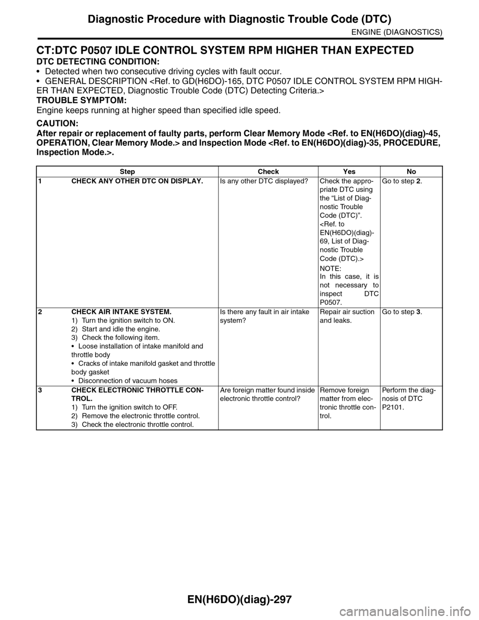
CT:DTC P0507 IDLE CONTROL SYSTEM RPM HIGHER THAN EXPECTED
DTC DETECTING CONDITION:
•Detected when two consecutive driving cycles with fault occur.
•GENERAL DESCRIPTION
TROUBLE SYMPTOM:
Engine keeps running at higher speed than specified idle speed.
CAUTION:
After repair or replacement of faulty parts, perform Clear Memory Mode
Step Check Yes No
1CHECK ANY OTHER DTC ON DISPLAY.Is any other DTC displayed? Check the appro-
priate DTC using
the “List of Diag-
nostic Trouble
Code (DTC)”.
69, List of Diag-
nostic Trouble
Code (DTC).>
NOTE:In this case, it is
not necessary to
inspect DTC
P0507.
Go to step 2.
2CHECK AIR INTAKE SYSTEM.
1) Turn the ignition switch to ON.
2) Start and idle the engine.
3) Check the following item.
•Loose installation of intake manifold and
throttle body
•Cracks of intake manifold gasket and throttle
body gasket
•Disconnection of vacuum hoses
Is there any fault in air intake
system?
Repair air suction
and leaks.
Go to step 3.
3CHECK ELECTRONIC THROTTLE CON-
TROL.
1) Turn the ignition switch to OFF.
2) Remove the electronic throttle control.
3) Check the electronic throttle control.
Are foreign matter found inside
electronic throttle control?
Remove foreign
matter from elec-
tronic throttle con-
trol.
Per fo r m th e di ag -
nosis of DTC
P2101.
Page 1461 of 2453
EN(H6DO)(diag)-300
Diagnostic Procedure with Diagnostic Trouble Code (DTC)
ENGINE (DIAGNOSTICS)
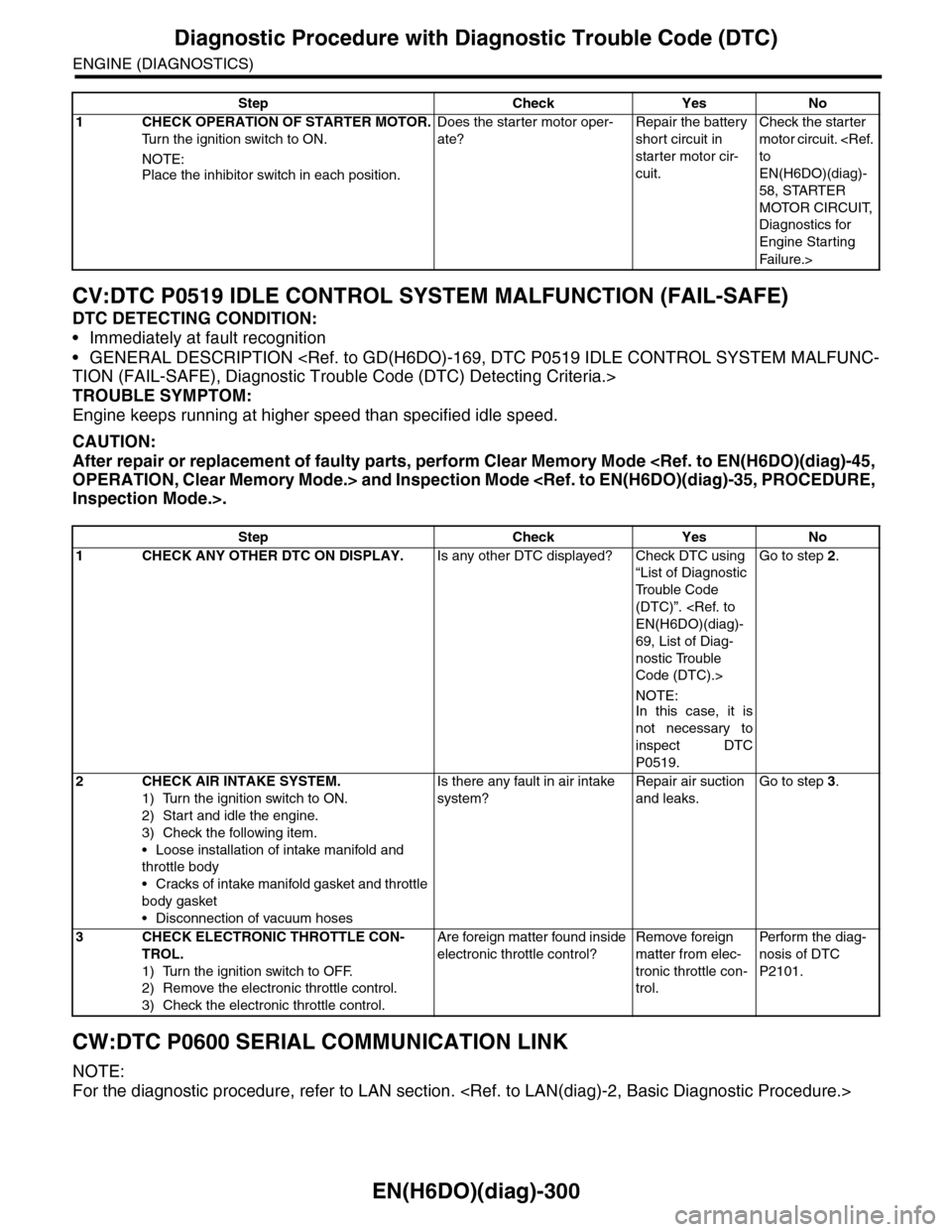
CV:DTC P0519 IDLE CONTROL SYSTEM MALFUNCTION (FAIL-SAFE)
DTC DETECTING CONDITION:
•Immediately at fault recognition
•GENERAL DESCRIPTION
TROUBLE SYMPTOM:
Engine keeps running at higher speed than specified idle speed.
CAUTION:
After repair or replacement of faulty parts, perform Clear Memory Mode
CW:DTC P0600 SERIAL COMMUNICATION LINK
NOTE:
For the diagnostic procedure, refer to LAN section.
Step Check Yes No
1CHECK OPERATION OF STARTER MOTOR.
Tu r n t h e i g n i t i o n s w i t c h t o O N .
NOTE:
Place the inhibitor switch in each position.
Does the starter motor oper-
ate?
Repair the battery
short circuit in
starter motor cir-
cuit.
Check the starter
motor circuit.
EN(H6DO)(diag)-
58, STARTER
MOTOR CIRCUIT,
Diagnostics for
Engine Starting
Fai lu r e.>
Step Check Yes No
1CHECK ANY OTHER DTC ON DISPLAY.Is any other DTC displayed? Check DTC using
“List of Diagnostic
Tr o u b l e C o d e
(DTC)”.
69, List of Diag-
nostic Trouble
Code (DTC).>
NOTE:In this case, it is
not necessary to
inspect DTC
P0519.
Go to step 2.
2CHECK AIR INTAKE SYSTEM.
1) Turn the ignition switch to ON.
2) Start and idle the engine.
3) Check the following item.
•Loose installation of intake manifold and
throttle body
•Cracks of intake manifold gasket and throttle
body gasket
•Disconnection of vacuum hoses
Is there any fault in air intake
system?
Repair air suction
and leaks.
Go to step 3.
3CHECK ELECTRONIC THROTTLE CON-
TROL.
1) Turn the ignition switch to OFF.
2) Remove the electronic throttle control.
3) Check the electronic throttle control.
Are foreign matter found inside
electronic throttle control?
Remove foreign
matter from elec-
tronic throttle con-
trol.
Per fo r m th e di ag -
nosis of DTC
P2101.
Page 1492 of 2453
EN(H6DO)(diag)-331
Diagnostic Procedure with Diagnostic Trouble Code (DTC)
ENGINE (DIAGNOSTICS)
Step Check Yes No
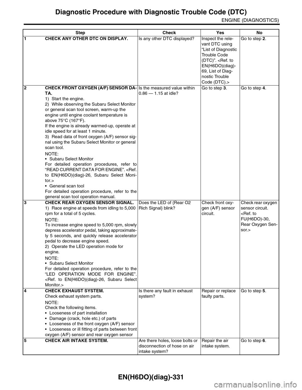
1CHECK ANY OTHER DTC ON DISPLAY.Is any other DTC displayed? Inspect the rele-
vant DTC using
“List of Diagnostic
Tr o u b l e C o d e
(DTC)”.
69, List of Diag-
nostic Trouble
Code (DTC).>
Go to step 2.
2CHECK FRONT OXYGEN (A/F) SENSOR DA-
TA.
1) Start the engine.
2) While observing the Subaru Select Monitor
or general scan tool screen, warm-up the
engine until engine coolant temperature is
above 75°C (167°F).
If the engine is already warmed-up, operate at
idle speed for at least 1 minute.
3) Read data of front oxygen (A/F) sensor sig-
nal using the Subaru Select Monitor or general
scan tool.
NOTE:
•Subaru Select Monitor
For detailed operation procedures, refer to
“READ CURRENT DATA FOR ENGINE”.
tor.>
•General scan tool
For detailed operation procedure, refer to the
general scan tool operation manual.
Is the measured value within
0.86 — 1.15 at idle?
Go to step 3.Go to step 4.
3CHECK REAR OXYGEN SENSOR SIGNAL.
1) Race engine at speeds from idling to 5,000
rpm for a total of 5 cycles.
NOTE:To increase engine speed to 5,000 rpm, slowly
depress accelerator pedal, taking approximate-
ly 5 seconds, and quickly release accelerator
pedal to decrease engine speed.
2) Operate the LED operation mode for
engine.
NOTE:•Subaru Select Monitor
For detailed operation procedure, refer to the
“LED OPERATION MODE FOR ENGINE”.
Does the LED of {Rear O2
Rich Signal} blink?
Check front oxy-
gen (A/F) sensor
circuit.
Check rear oxygen
sensor circuit.
Rear Oxygen Sen-
sor.>
4 CHECK EXHAUST SYSTEM.
Check exhaust system parts.
NOTE:Check the following items.
•Looseness of part installation
•Damage (crack, hole etc.) of parts
•Looseness of the front oxygen (A/F) sensor
•Looseness or ill fitting of parts between front
oxygen (A/F) sensor and rear oxygen sensor
Is there any fault in exhaust
system?
Repair or replace
faulty par ts.
Go to step 5.
5CHECK AIR INTAKE SYSTEM.Are there holes, loose bolts or
disconnection of hose on air
intake system?
Repair the air
intake system.
Go to step 6.