Page 1618 of 2453

GD(H6DO)-6
List of Diagnostic Trouble Code (DTC)
GENERAL DESCRIPTION
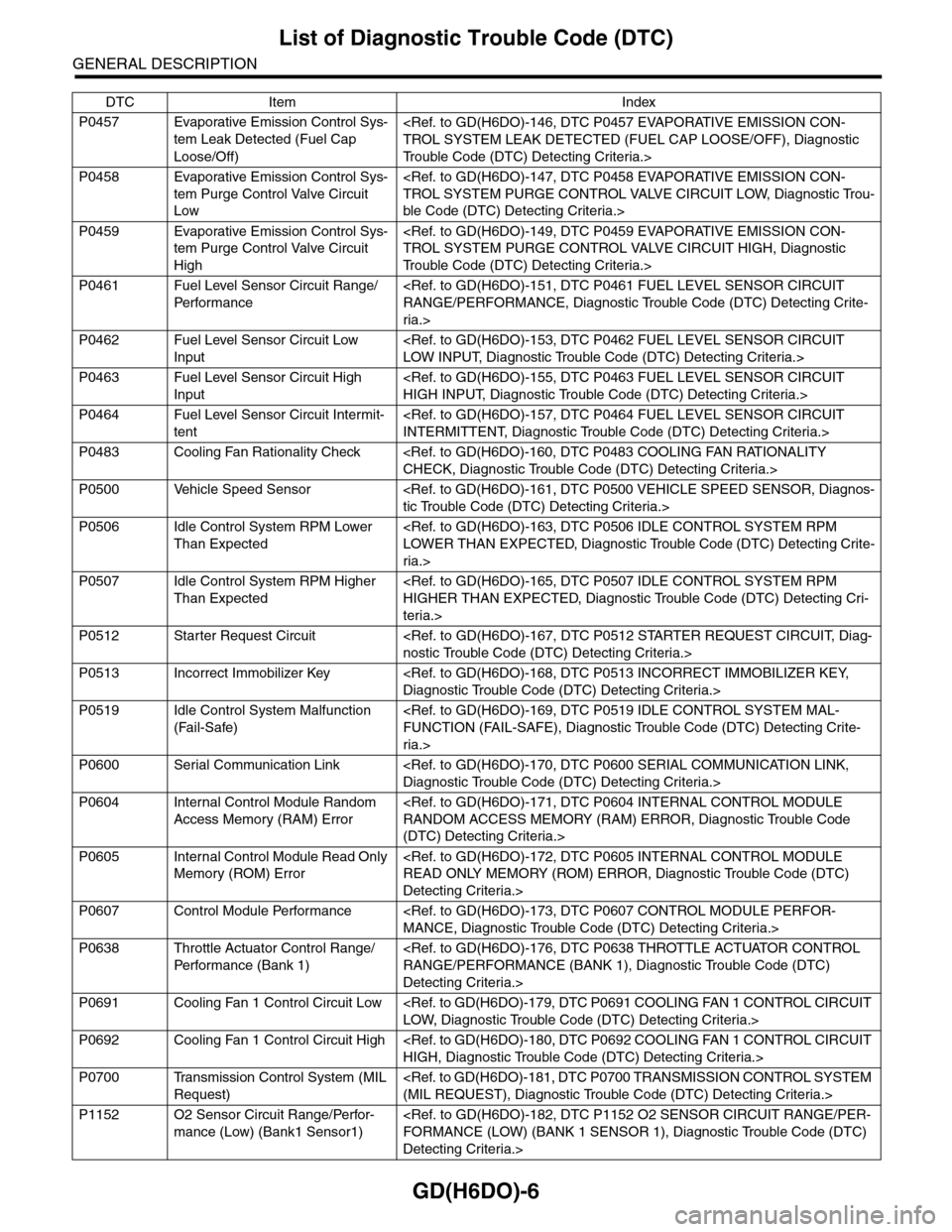
P0457 Evaporative Emission Control Sys-
tem Leak Detected (Fuel Cap
Loose/Off)
TROL SYSTEM LEAK DETECTED (FUEL CAP LOOSE/OFF), Diagnostic
Tr o u b l e C o d e ( D T C ) D e t e c t i n g C r i t e r i a . >
P0458 Evaporative Emission Control Sys-
tem Purge Control Valve Circuit
Low
TROL SYSTEM PURGE CONTROL VALVE CIRCUIT LOW, Diagnostic Trou-
ble Code (DTC) Detecting Criteria.>
P0459 Evaporative Emission Control Sys-
tem Purge Control Valve Circuit
High
TROL SYSTEM PURGE CONTROL VALVE CIRCUIT HIGH, Diagnostic
Tr o u b l e C o d e ( D T C ) D e t e c t i n g C r i t e r i a . >
P0461 Fuel Level Sensor Circuit Range/
Per fo r m an ce
RANGE/PERFORMANCE, Diagnostic Trouble Code (DTC) Detecting Crite-
ria.>
P0462 Fuel Level Sensor Circuit Low
Input
LOW INPUT, Diagnostic Trouble Code (DTC) Detecting Criteria.>
P0463 Fuel Level Sensor Circuit High
Input
HIGH INPUT, Diagnostic Trouble Code (DTC) Detecting Criteria.>
P0464 Fuel Level Sensor Circuit Intermit-
tent
INTERMITTENT, Diagnostic Trouble Code (DTC) Detecting Criteria.>
P0483 Cooling Fan Rationality Check
CHECK, Diagnostic Trouble Code (DTC) Detecting Criteria.>
P0500 Vehicle Speed Sensor
tic Trouble Code (DTC) Detecting Criteria.>
P0506 Idle Control System RPM Lower
Than Expected
LOWER THAN EXPECTED, Diagnostic Trouble Code (DTC) Detecting Crite-
ria.>
P0507 Idle Control System RPM Higher
Than Expected
HIGHER THAN EXPECTED, Diagnostic Trouble Code (DTC) Detecting Cri-
teria.>
P0512 Starter Request Circuit
nostic Trouble Code (DTC) Detecting Criteria.>
P0513 Incorrect Immobilizer Key
Diagnostic Trouble Code (DTC) Detecting Criteria.>
P0519 Idle Control System Malfunction
(Fail-Safe)
FUNCTION (FAIL-SAFE), Diagnostic Trouble Code (DTC) Detecting Crite-
ria.>
P0600 Serial Communication Link
Diagnostic Trouble Code (DTC) Detecting Criteria.>
P0604 Internal Control Module Random
Access Memory (RAM) Error
RANDOM ACCESS MEMORY (RAM) ERROR, Diagnostic Trouble Code
(DTC) Detecting Criteria.>
P0605 Internal Control Module Read Only
Memory (ROM) Error
READ ONLY MEMORY (ROM) ERROR, Diagnostic Trouble Code (DTC)
Detecting Criteria.>
P0607 Control Module Performance
MANCE, Diagnostic Trouble Code (DTC) Detecting Criteria.>
P0638 Throttle Actuator Control Range/
Per fo r m an ce ( B an k 1 )
RANGE/PERFORMANCE (BANK 1), Diagnostic Trouble Code (DTC)
Detecting Criteria.>
P0691 Cooling Fan 1 Control Circuit Low
LOW, Diagnostic Trouble Code (DTC) Detecting Criteria.>
P0692 Cooling Fan 1 Control Circuit High
HIGH, Diagnostic Trouble Code (DTC) Detecting Criteria.>
P0700 Transmission Control System (MIL
Request)
(MIL REQUEST), Diagnostic Trouble Code (DTC) Detecting Criteria.>
P1152 O2 Sensor Circuit Range/Perfor-
mance (Low) (Bank1 Sensor1)
FORMANCE (LOW) (BANK 1 SENSOR 1), Diagnostic Trouble Code (DTC)
Detecting Criteria.>
DTC Item Index
Page 1620 of 2453

GD(H6DO)-8
List of Diagnostic Trouble Code (DTC)
GENERAL DESCRIPTION
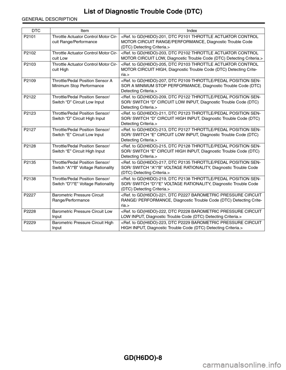
P2101 Throttle Actuator Control Motor Cir-
cuit Range/Performance
MOTOR CIRCUIT RANGE/PERFORMANCE, Diagnostic Trouble Code
(DTC) Detecting Criteria.>
P2102 Throttle Actuator Control Motor Cir-
cuit Low
MOTOR CIRCUIT LOW, Diagnostic Trouble Code (DTC) Detecting Criteria.>
P2103 Throttle Actuator Control Motor Cir-
cuit High
MOTOR CIRCUIT HIGH, Diagnostic Trouble Code (DTC) Detecting Crite-
ria.>
P2109 Throttle/Pedal Position Sensor A
Minimum Stop Performance
SOR A MINIMUM STOP PERFORMANCE, Diagnostic Trouble Code (DTC)
Detecting Criteria.>
P2122 Throttle/Pedal Position Sensor/
Switch “D” Circuit Low Input
SOR/ SWITCH “D” CIRCUIT LOW INPUT, Diagnostic Trouble Code (DTC)
Detecting Criteria.>
P2123 Throttle/Pedal Position Sensor/
Switch “D” Circuit High Input
SOR/ SWITCH “D” CIRCUIT HIGH INPUT, Diagnostic Trouble Code (DTC)
Detecting Criteria.>
P2127 Throttle/Pedal Position Sensor/
Switch “E” Circuit Low Input
SOR/ SWITCH “E” CIRCUIT LOW INPUT, Diagnostic Trouble Code (DTC)
Detecting Criteria.>
P2128 Throttle/Pedal Position Sensor/
Switch “E” Circuit High Input
SOR/ SWITCH “E” CIRCUIT HIGH INPUT, Diagnostic Trouble Code (DTC)
Detecting Criteria.>
P2135 Throttle/Pedal Position Sensor/
Switch “A”/“B” Voltage Rationality
SOR/ SWITCH “A”/“B” VOLTAGE RATIONALITY, Diagnostic Trouble Code
(DTC) Detecting Criteria.>
P2138 Throttle/Pedal Position Sensor/
Switch “D”/“E” Voltage Rationality
SOR/ SWITCH “D”/“E” VOLTAGE RATIONALITY, Diagnostic Trouble Code
(DTC) Detecting Criteria.>
P2227 Barometric Pressure Circuit
Range/Performance
RANGE/ PERFORMANCE, Diagnostic Trouble Code (DTC) Detecting Crite-
ria.>
P2228 Barometric Pressure Circuit Low
Input
LOW INPUT, Diagnostic Trouble Code (DTC) Detecting Criteria.>
P2229 Barometric Pressure Circuit High
Input
HIGH INPUT, Diagnostic Trouble Code (DTC) Detecting Criteria.>
DTC Item Index
Page 1788 of 2453

GD(H6DO)-176
Diagnostic Trouble Code (DTC) Detecting Criteria
GENERAL DESCRIPTION
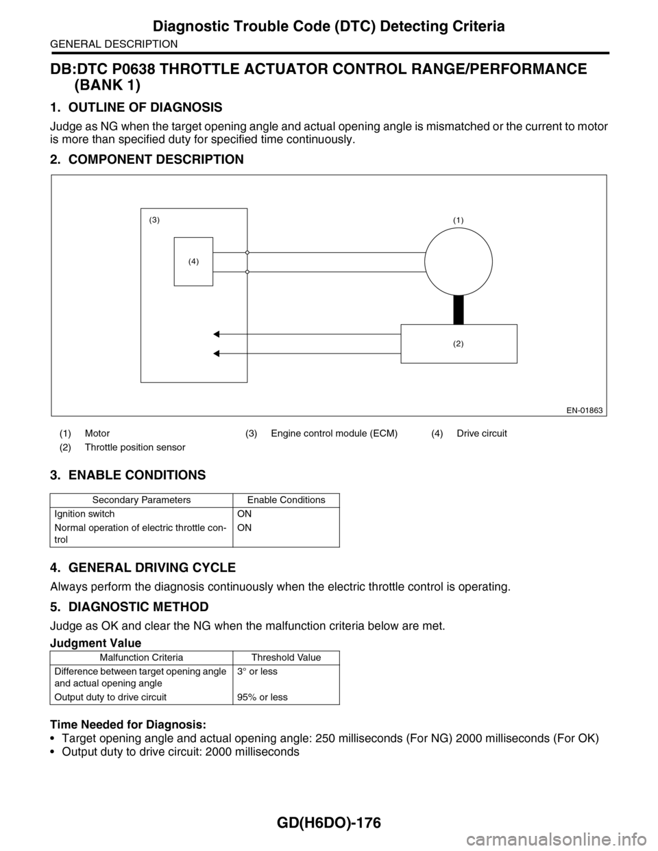
DB:DTC P0638 THROTTLE ACTUATOR CONTROL RANGE/PERFORMANCE
(BANK 1)
1. OUTLINE OF DIAGNOSIS
Judge as NG when the target opening angle and actual opening angle is mismatched or the current to motor
is more than specified duty for specified time continuously.
2. COMPONENT DESCRIPTION
3. ENABLE CONDITIONS
4. GENERAL DRIVING CYCLE
Always perform the diagnosis continuously when the electric throttle control is operating.
5. DIAGNOSTIC METHOD
Judge as OK and clear the NG when the malfunction criteria below are met.
Time Needed for Diagnosis:
•Target opening angle and actual opening angle: 250 milliseconds (For NG) 2000 milliseconds (For OK)
•Output duty to drive circuit: 2000 milliseconds
(1) Motor (3) Engine control module (ECM) (4) Drive circuit
(2) Throttle position sensor
Secondary Parameters Enable Conditions
Ignition switch ON
Normal operation of electric throttle con-
trol
ON
Judgment Value
Malfunction Criteria Threshold Value
Difference between target opening angle
and actual opening angle
3° or less
Output duty to drive circuit 95% or less
EN-01863
(3)
(4)
(1)
(2)
Page 1813 of 2453
GD(H6DO)-201
Diagnostic Trouble Code (DTC) Detecting Criteria
GENERAL DESCRIPTION
EC:DTC P2101 THROTTLE ACTUATOR CONTROL MOTOR CIRCUIT RANGE/
PERFORMANCE
1. OUTLINE OF DIAGNOSIS
Judge as NG when the motor current becomes large or drive circuit is heated.
2. COMPONENT DESCRIPTION
3. ENABLE CONDITIONS
4. GENERAL DRIVING CYCLE
Always perform the diagnosis continuously.
5. DIAGNOSTIC METHOD
Judge as OK and clear the NG when the malfunction criteria below are met.
(1) Engine control module (ECM) (4) Drive circuit (6) Electronic throttle control relay
(2) Detecting circuit (5) Temperature detection circuit (7) Motor
(3) Overcurrent detection circuit
Secondary Parameters Enable Conditions
Under control of electronic throttle con-
trol
ON
Judgment Value
Malfunction Criteria Threshold Value
Motor current≤ 8 A
Drive circuit inner temperature≤ 175°C (347°F)
EN-01867
(3)(2)
(5)(2)
(4)
(1)
(6)
(7)
12V 12V
Page 1815 of 2453

GD(H6DO)-203
Diagnostic Trouble Code (DTC) Detecting Criteria
GENERAL DESCRIPTION
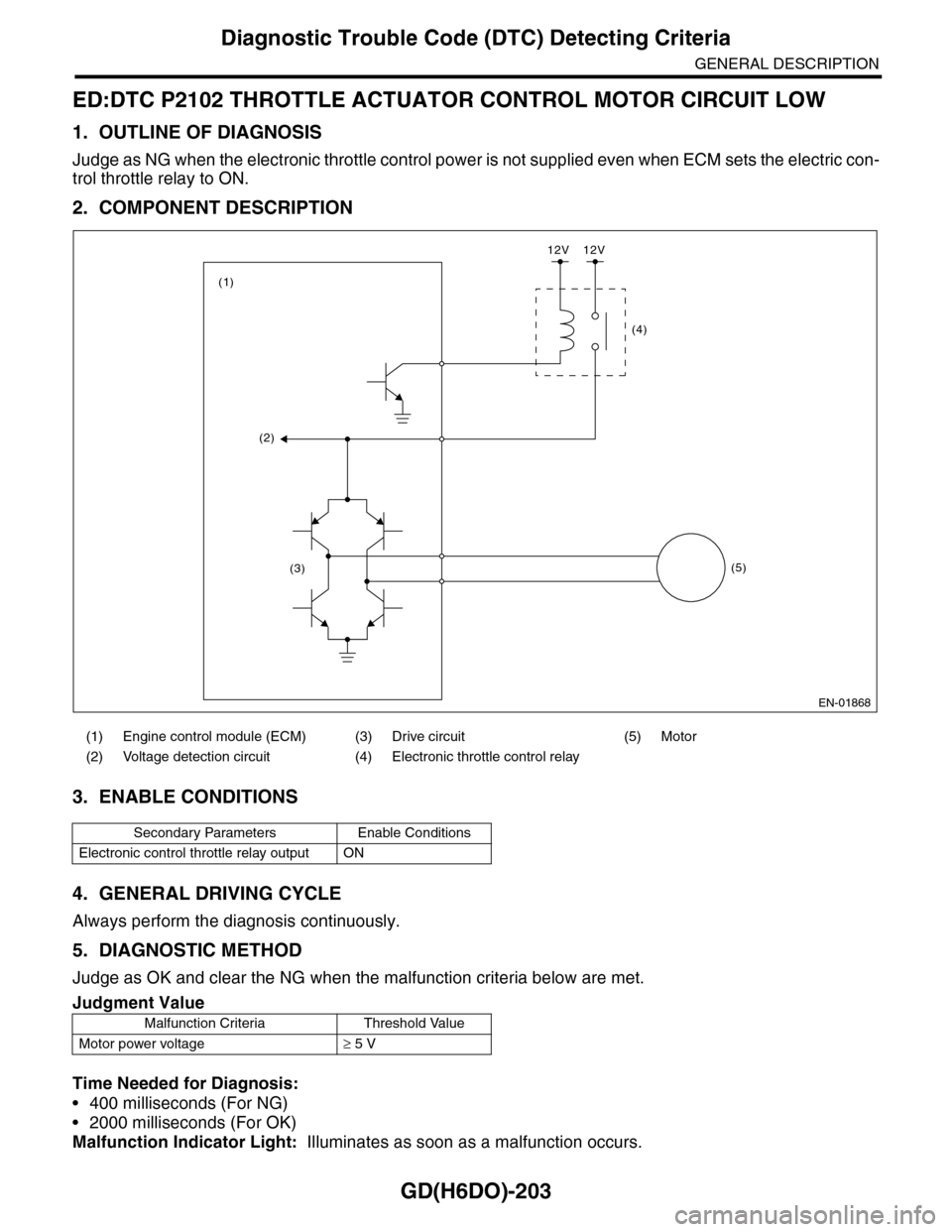
ED:DTC P2102 THROTTLE ACTUATOR CONTROL MOTOR CIRCUIT LOW
1. OUTLINE OF DIAGNOSIS
Judge as NG when the electronic throttle control power is not supplied even when ECM sets the electric con-
trol throttle relay to ON.
2. COMPONENT DESCRIPTION
3. ENABLE CONDITIONS
4. GENERAL DRIVING CYCLE
Always perform the diagnosis continuously.
5. DIAGNOSTIC METHOD
Judge as OK and clear the NG when the malfunction criteria below are met.
Time Needed for Diagnosis:
•400 milliseconds (For NG)
•2000 milliseconds (For OK)
Malfunction Indicator Light: Illuminates as soon as a malfunction occurs.
(1) Engine control module (ECM) (3) Drive circuit (5) Motor
(2) Voltage detection circuit (4) Electronic throttle control relay
Secondary Parameters Enable Conditions
Electronic control throttle relay output ON
Judgment Value
Malfunction Criteria Threshold Value
Motor power voltage≥ 5 V
EN-01868
(2)
(3)
(1)
(4)
(5)
12V 12V
Page 1817 of 2453
GD(H6DO)-205
Diagnostic Trouble Code (DTC) Detecting Criteria
GENERAL DESCRIPTION
EE:DTC P2103 THROTTLE ACTUATOR CONTROL MOTOR CIRCUIT HIGH
1. OUTLINE OF DIAGNOSIS
Judge as NG when the electronic throttle control power is not supplied even when ECM sets the electric throt-
tle control relay to OFF.
2. COMPONENT DESCRIPTION
3. ENABLE CONDITIONS
4. GENERAL DRIVING CYCLE
•When ignition switch ON → OFF
•Ignition switch OFF → ON (Only after clearing memory)
5. DIAGNOSTIC METHOD
Judge as OK and clear the NG when the malfunction criteria below are met.
(1) Engine control module (ECM) (3) Drive circuit (5) Motor
(2) Voltage detection circuit (4) Electronic throttle control relay
Secondary Parameters Enable Conditions
Electronic control throttle relay output OFF
Judgment Value
Malfunction Criteria Threshold Value
Motor power voltage≤ 5 V
EN-01868
(2)
(3)
(1)
(4)
(5)
12V 12V
Page 2030 of 2453
5AT-14
General Description
AUTOMATIC TRANSMISSION
10.TRANSMISSION CONTROL DEVICE & PARKING SUPPORT
(1) Bracket (9) Parking support actuator (16) Reduction driven gear
(2) Floating bracket (10) Parking pawl shaft (17) Ball bearing
(3) AT main case (11) Return spring
(4) Range select lever (12) Parking pawlTightening torque: N·m (kgf-m, ft-lb)
(5) Straight pin (13) Ball bearingT1: 6 (0.6, 4.4)
(6) Detent spring (14) Snap ringT2: 25 (2.5, 18)
(7) Manual plate (15) Parking gearT3:
(8) Parking rod
T2
T2
T3
T1
T1
(1)
(2)
(3)
(10)
(11)
(8)
(7)
(5)(4)
(6)
(12)
(13)
(14)
(15)
(16)
(17)
(9)
AT-03248
Page 2089 of 2453
5AT-73
Parking Pawl
AUTOMATIC TRANSMISSION
29.Parking Pawl
A: REMOVAL
1) Remove the transmission assembly from vehicle
body.
Transmission Assembly.>
2) Remove the extension case.
REMOVAL, Extension Case.>
3) Remove the center differential carrier.
5AT-71, REMOVAL, Center Differential Carrier.>
4) Remove the front vehicle speed sensor.
5AT-47, REMOVAL, Front Vehicle Speed Sensor.>
5) Remove the parking support actuator.
6) Remove the parking pawl, parking pawl shaft
and return spring.
B: INSTALLATION
1) Set the transmission to the “N” range.
2) Install the parking pawl, parking pawl shaft and
return spring.
3) Install the parking support actuator.
Tightening torque:
10±2 N·m (1.0±0.2 kgf-m, 7.4±1.5 ft-lb)
4) Using the ST, tighten the bolts which tightened in
step 4) with specified angle.
Tightening angle:
17°±2°
ST 18854AA000 ANGLE GAUGE
NOTE:
Do not use extension as much as possible.
AT-03236
AT-03272
AT-03272
AT-03236
AT-02071ST
AT-02072
ST