2009 SUBARU TRIBECA door
[x] Cancel search: doorPage 384 of 2453
AC(diag)-7
Electrical Component Location
HVAC SYSTEM (AUTO A/C) (DIAGNOSTICS)
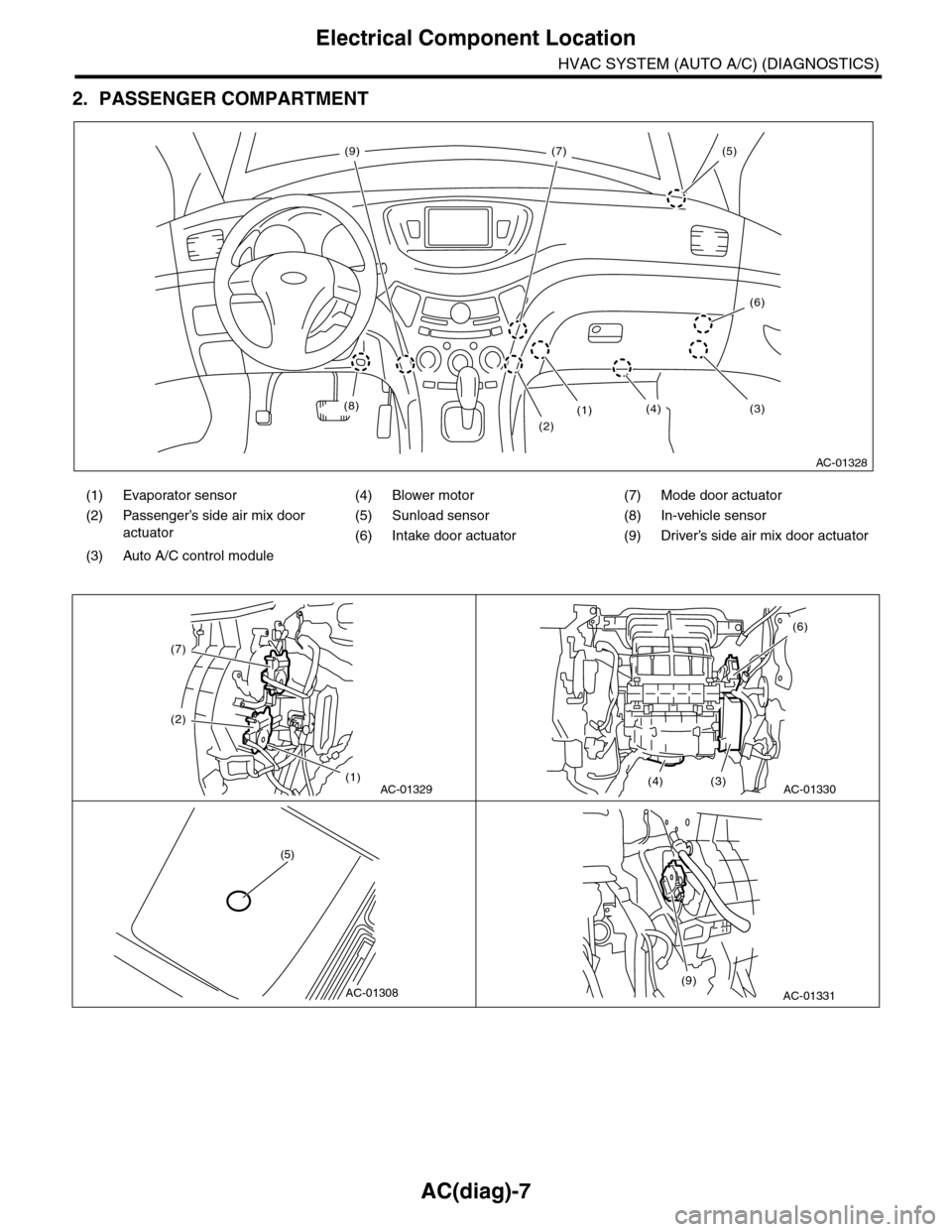
2. PASSENGER COMPARTMENT
(1) Evaporator sensor (4) Blower motor (7) Mode door actuator
(2) Passenger’s side air mix door
actuator
(5) Sunload sensor (8) In-vehicle sensor
(6) Intake door actuator (9) Driver’s side air mix door actuator
(3) Auto A/C control module
AC-01328
(8)
(2)
(1)(3)(4)
(5)
(6)
(7)(9)
AC-01329
(7)
(2)
(1)AC-01330
(6)
(3)(4)
AC-01308
(5)
AC-01331(9)
Page 385 of 2453

AC(diag)-8
Auto A/C Control Module I/O Signal
HVAC SYSTEM (AUTO A/C) (DIAGNOSTICS)
4. Auto A/C Control Module I/O Signal
A: ELECTRICAL SPECIFICATION
Te r m i n a l N o . D e s c r i p t i o n M e a s u r i n g c o n d i t i o n S p e c i f i c a t i o n
A1 Battery power supply Ignition switch: OFF Battery voltage
A2 ACC power supply Ignition switch: ACC Battery voltage
A3Mode door actuator position sig-
nal
Mode door: FACE position 4 V
Mode door: DEF position 1 V
A4Passenger’s side air mix door
actuator position signal
Air mix door: Maximum cool position 4 V
Air mix door: Maximum hot position 1 V
A5 In-vehicle sensor Ignition switch: ON Less than 5 V
A6 Sunload sensor Ignition switch: ON, With Sunload (No sunload: 0.8 V) 3 V
A7Driver’s seat heater temperature
sensorIgnition switch: ON Less than 5 V
A8 Sensor power supply Ignition switch: ON 5 V
A9 Ignition power supply Ignition switch: ON Battery voltage
A10 A/C cut signalIgnition switch: ON Battery voltage
When pressure SW is operating 0 V
A12Driver’s side air mix door actuator
position signal
Air mix door: Maximum cool position 4 V
Air mix door: Maximum hot position 1 V
A13 Evaporator sensor Ignition switch: ON Less than 5 V
A14Passenger’s seat heater tempera-
ture sensorIgnition switch: ON Less than 5 V
A15 Sensor ground Continuity to chassis ground 0 Ω
A16 Ground Continuity to chassis ground 0 Ω
B1 CAN communication (HI side) Ignition switch: ON Pulse signal *1
B2Blower motor voltage feedback
signal
Blower level: Manual Lo 7.6 V
Blower level: Manual M3 3.7 V
Blower level: Manual Hi Less than 1 V
B3Blower motor power MOS gate
control signalIgnition switch : ON, Blower switch : ON1 V — battery
voltage
B6 Magnet clutch signalTe m p e r a t u r e s e t t i n g : M a x i m u m C O O L , M O D E : M a n u a l
DEF, A/C: ONBattery voltage
AC-01334
10
20 19 18 17 16 15 14
13 12 11987654 321
1016 15 14 13 12 119
87654 321
B: B283
A: B282
232122242526
Page 386 of 2453

AC(diag)-9
Auto A/C Control Module I/O Signal
HVAC SYSTEM (AUTO A/C) (DIAGNOSTICS)
*1: Unable to measure the voltage for digital signal.
*2: Voltage immediately after switching FACE ⇔ DEF or maximum COOL ⇔ maximum HOT (when the damper door is operat-
ing.) for mode door and air mix door
*3: Voltage immediately after the operation for the seat heater (Always measure the voltage immediately after turning the seat
heater to ON because once reached to the target value, it switches to ON/OFF action.)
B: WIRING DIAGRAM
1. AIR CONDITIONER AUTO A/C MODEL
B7Mode door actuator power supply
(FACE)
When switching mode door from DEF → FACE
Battery voltage
— 2.5 V or more
*2
When switching mode door from FACE → DEF Less than 1 V *2
B8
Passenger’s side air mix door
actuator power supply (COOL
side)
When switching air mix door from HOT → COOL
Battery voltage
— 2.5 V or more
*2
When switching air mix door from COOL → HOT Less than 1 V *2
B9Driver’s side air mix door actuator
power supply (COOL side)
When switching air mix door from HOT → COOL
Battery voltage
— 2.5 V or more
*2
When switching air mix door from COOL → HOT Less than 1 V *2
B10 Inlet opening motor (FRESH side)FRESH Less than 1 V
RECIRC Battery voltage
B11 Driver’s seat heater Driver’s seat heater: ON (3 stages) Less than 1 V *3
B13 Passenger’s seat heater Passenger’s seat heater: ON (3 stages) Less than 1 V *3
B14 CAN communication (Lo side) Ignition switch: ON Pulse signal *1
B16 Blower motor relayBlower motor: Stopped Battery voltage
Blower motor: Operated Less than 1 V
B18Panel communication (transmitter
side)Ignition switch: ON Pulse signal *1
B19Panel communication (receiver
side)Ignition switch: ON Pulse signal *1
B20 Mode door (DEF) side
Mode: DEF ⇒ FACE Less than 1 V
Mode: FACE ⇒ DEFBattery voltage
— 2.5 V or more
B21 Passenger’s side air mix door
Air mix: Maximum HOT ⇒ maximum COOL Less than 1 V
Air mix: Maximum COOL ⇒ maximum HOTBattery voltage
— 2.5 V or more
B22 Driver’s side air mix door
Air mix: Maximum HOT ⇒ maximum COOL Less than 1 V
Air mix: Maximum COOL ⇒ maximum HOTBattery voltage
— 2.5 V or more
B23Inlet opening motor (RECIRC
side)
RECIRC Less than 1 V
FRESH Battery voltage
B24 Driver’s seat heater ground Continuity to chassis ground 0 Ω
B25 Passenger’s seat heater ground Continuity to chassis ground 0 Ω
Te r m i n a l N o . D e s c r i p t i o n M e a s u r i n g c o n d i t i o n S p e c i f i c a t i o n
Page 391 of 2453

AC(diag)-14
Diagnostic Chart for Self-diagnosis
HVAC SYSTEM (AUTO A/C) (DIAGNOSTICS)
4. SENSOR CHECK TABLE
NOTE:
When the sunload sensor check is performed indoors or in the shade, it could be diagnosed as having an
open circuit. Always check the sunload sensor with the sun shining on it.
*1: “AUTO” display does not blink when past malfunction occurred. Past malfunction means that abnormal signals were contin-
uously input for a certain time in the past.
*2: Present malfunction only is displayed for sunload sensor open circuit.
5. OPERATING MODE TABLE
*Same opening angle for both driver’s and passenger’s side
Display screen (Malfunction at
present) *1Sensor Trouble contents
21/AUTO BlinkIn-vehicle sensorOpen
–21/AUTO BlinkShort
22/AUTO Blink Ambient sensor Sensor trouble or communication malfunction
23/AUTO BlinkEvaporator sensorOpen
–23/AUTO BlinkShort
24/AUTO Blink Engine coolant temperature sensor Sensor trouble or communication malfunction
25 BlinkSunload sensorOpen *2
–25/AUTO BlinkShort
26/AUTO BlinkDriver's side air mix door actuator
potentiometer
COOL
27/AUTO BlinkHOT
–26/AUTO BlinkPassenger’s side air mix door actua-
tor potentiometer
COOL
–27/AUTO BlinkHOT
28/AUTO BlinkMode door actuator potentiometerFA C E
29/AUTO BlinkDEF
41/AUTO BlinkSeat heater thermistor (Driver’s
side)
Open
–41/AUTO BlinkShort
42/AUTO BlinkSeat heater thermistor (Passenger’s
side)
Open
–42/AUTO BlinkShort
20 Blink When all conditions are normal
Display screenFRESH/RECIRC
doorMode door Air mix door* Blower fanA/C compressor (Mag-
net clutch)
31 FRESH FACE Maximum cool LO OFF
32 RECIRC FACE Maximum cool LO ON
33 RECIRC FACE Maximum cool M1 ON
34 FRESH B/L 50% M1 ON
35 FRESH HEAT 50% M1 ON
36 FRESH HEAT Maximum hot M3 ON
37 FRESH D/H Maximum hot M3 ON
38 FRESH DEF Maximum hot HI ON
Page 401 of 2453
AC(diag)-24
Diagnostic Procedure for Actuators
HVAC SYSTEM (AUTO A/C) (DIAGNOSTICS)
7. Diagnostic Procedure for Actuators
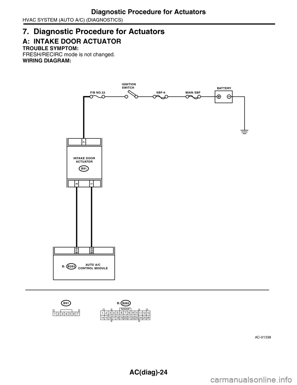
A: INTAKE DOOR ACTUATOR
TROUBLE SYMPTOM:
FRESH/RECIRC mode is not changed.
WIRING DIAGRAM:
AC-01338
B91
MAIN SBFSBF-6F/B NO.22
7
31
B283
B23B10
B:
B91
1234567
AUTO A/CCONTROL MODULE
INTAKE DOORACTUATOR
IGNITIONSWITCHBATTERY
B283B:
1234567891014151617181920212223111213242526
Page 402 of 2453
AC(diag)-25
Diagnostic Procedure for Actuators
HVAC SYSTEM (AUTO A/C) (DIAGNOSTICS)
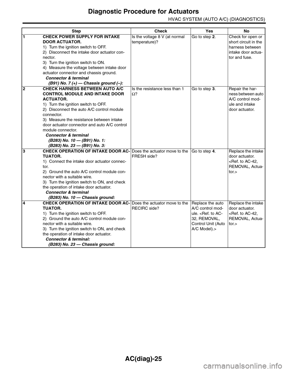
Step Check Yes No
1CHECK POWER SUPPLY FOR INTAKE
DOOR ACTUATOR.
1) Turn the ignition switch to OFF.
2) Disconnect the intake door actuator con-
nector.
3) Turn the ignition switch to ON.
4) Measure the voltage between intake door
actuator connector and chassis ground.
Connector & terminal
(B91) No. 7 (+) — Chassis ground (–):
Is the voltage 8 V (at normal
temperature)?
Go to step 2.Check for open or
short circuit in the
harness between
intake door actua-
tor and fuse.
2CHECK HARNESS BETWEEN AUTO A/C
CONTROL MODULE AND INTAKE DOOR
ACTUATOR.
1) Turn the ignition switch to OFF.
2) Disconnect the auto A/C control module
connector.
3) Measure the resistance between intake
door actuator connector and auto A/C control
module connector.
Connector & terminal
(B283) No. 10 — (B91) No. 1:
(B283) No. 23 — (B91) No. 3:
Is the resistance less than 1
Ω?
Go to step 3.Repair the har-
ness between auto
A/C control mod-
ule and intake
door actuator.
3CHECK OPERATION OF INTAKE DOOR AC-
TUATOR.
1) Connect the intake door actuator connec-
tor.
2) Ground the auto A/C control module con-
nector with a suitable wire.
3) Turn the ignition switch to ON, and check
the operation of intake door actuator.
Connector & terminal
(B283) No. 10 — Chassis ground:
Does the actuator move to the
FRESH side?
Go to step 4.Replace the intake
door actuator.
tor.>
4CHECK OPERATION OF INTAKE DOOR AC-
TUATOR.
1) Turn the ignition switch to OFF.
2) Ground the auto A/C control module con-
nector with a suitable wire.
3) Turn the ignition switch to ON, and check
the operation of intake door actuator.
Connector & terminal:
(B283) No. 23 — Chassis ground:
Does the actuator move to the
RECIRC side?
Replace the auto
A/C control mod-
ule.
Control Unit (Auto
A/C Model).>
Replace the intake
door actuator.
tor.>
Page 403 of 2453

AC(diag)-26
Diagnostic Procedure for Actuators
HVAC SYSTEM (AUTO A/C) (DIAGNOSTICS)
B: MODE DOOR ACTUATOR
TROUBLE SYMPTOM:
Air flow outlet is not changed.
WIRING DIAGRAM:
AC-01339
B77
3412 891011 12 13 14 15 16567
B282A:
B283B282
B77
B20
176
A15B7
B:A:
53
A8A3
12345
MODE DOOR ACTUATOR
AUTO A/CCONTROL MODULE
B283B:
1234567891014151617181920212223111213242526
Page 404 of 2453

AC(diag)-27
Diagnostic Procedure for Actuators
HVAC SYSTEM (AUTO A/C) (DIAGNOSTICS)
Step Check Yes No
1CHECK POWER SUPPLY FOR MODE DOOR
ACTUATOR POSITION SENSOR.
1) Turn the ignition switch to OFF.
2) Disconnect the mode door actuator con-
nector.
3) Turn the ignition switch and AUTO switch to
ON.
4) Measure the voltage between auto A/C
control module connector terminals.
Connector & terminal
(B282) No. 8 (+) — (B282) No. 15 (–):
Is the voltage approx. 5 V? Go to step 2.Replace the auto
A/C control mod-
ule.
Control Unit (Auto
A/C Model).>
2CHECK POWER SUPPLY FOR MODE DOOR
ACTUATOR.
Measure the voltage between auto A/C control
module connector and chassis ground after
turning the air flow control switch to FACE posi-
tion.
Connector & terminal
(B283) No. 7 (+) — Chassis ground (–):
Is the voltage 8 V (at normal
temperature)?
Go to step 3.Replace the auto
A/C control mod-
ule.
Control Unit (Auto
A/C Model).>
3CHECK POWER SUPPLY FOR MODE DOOR
ACTUATOR.
Measure the voltage between auto A/C control
module connector and chassis ground after
turning the air flow control switch to DEF posi-
tion.
Connector & terminal
(B283) No. 20 (+) — Chassis ground (–):
Is the voltage 8 V (at normal
temperature)?
Go to step 4.Replace the auto
A/C control mod-
ule.
4CHECK HARNESS BETWEEN AUTO A/C
CONTROL MODULE AND MODE DOOR AC-
TUATOR.
1) Turn the A/C and ignition switch to OFF.
2) Disconnect the auto A/C control module
connector.
3) Measure the resistance between auto A/C
control module and mode door actuator con-
nector.
Connector & terminal
(B77) No. 1 — (B282) No. 15:
(B77) No. 3 — (B282) No. 8:
(B77) No. 5 — (B282) No. 3:
(B77) No. 6 — (B283) No. 20:
(B77) No. 7 — (B283) No. 7:
Is the resistance less than 1
Ω?
Go to step 5.Repair the har-
ness between auto
A/C control mod-
ule and mode door
actuator.
5CHECK MODE DOOR ACTUATOR POSI-
TION SWITCH SIGNAL.
1) Connect the connector of auto A/C control
module and mode door actuator.
2) Turn the ignition switch and AUTO switch to
ON.
3) Check the voltage between auto A/C con-
trol module connector terminals while chang-
ing the mode between DEF and FACE.
Connector & terminal
(B282) No. 3 (+) — (B282) No. 15 (–):
Does the voltage change
between 1 V (DEF) and 4 V
(FACE)?
Go to step 6.Replace the mode
door actuator.
tor.>
6CHECK POOR CONTACT.
Check poor contact of auto A/C control module
and connector.
Is there poor contact in con-
nector?
Repair the con-
nector.
Replace the auto
A/C control mod-
ule.
Control Unit (Auto
A/C Model).>