Page 279 of 2453
EI-37
Glove Box
EXTERIOR/INTERIOR TRIM
14.Glove Box
A: REMOVAL
1) Remove the front door scuff plate and front pillar
lower trim.
2) Remove the instrument panel side cover RH.
3) Remove the console side panel lower RH.
4) Remove the clips, and remove the glove box
lower cover.
5) Remove the screws (A) and hooks (B), and dis-
connect the connector, and then remove the glove
box assembly.
6) Remove the clips (A), left and right stoppers of
glove box lid (B) and damper strap, and then re-
move the glove box lid.
NOTE:
The glove box lid can be removed without using the
glove box assembly.
B: INSTALLATION
Install in the reverse order of removal.
(A) Hook
(A) Hook
EI-01295:(A)
EI-01296:(A)
EI-01297
EI-01298
(A)
(A)
(A)
(A)
(A)
(A)
:(B)
Page 283 of 2453

EI-41
Instrument Panel Assembly
EXTERIOR/INTERIOR TRIM
13) Make sure that the instrument panel upper is
removed from the steering support beam
14) Disconnect the connectors, and remove the in-
strument panel from vehicle body.
15) Remove the heater vent duct.
REMOVAL, Heater Vent Duct.>
16) Remove the air vent grille.
MOVAL, Air Vent Grille.>
17) Remove the passenger airbag module.
to AB-16, REMOVAL, Passenger’s Airbag Mod-
ule.>
2. STEERING SUPPORT BEAM
1) Remove the instrument panel upper.
2) Remove the bolts, and then remove the knee
guard plate.
3) Remove the steering shaft from the steering
support beam.
Steering Column.>
4) Remove the bolts and remove the steering sup-
port beam.
3. INSTRUMENT PANEL ASSEMBLY
1) Disconnect the ground cable from battery and
wait for at least 20 seconds before starting work.
2) Remove the console box.
MOVAL, Console Box.>
3) Remove the instrument panel lower cover.
to EI-36, REMOVAL, Instrument Panel Lower Cov-
er.>
4) Remove the glove box.
AL, Glove Box.>
5) Remove the center console.
MOVAL, Center Console.>
6) Remove the front pillar upper trim.
43, REMOVAL, Side Trim.>
7) Remove the steering shaft from the steering
support beam.
Steering Column.>
8) Disconnect the connectors, and remove the in-
strument panel from vehicle body.
9) Remove the bolts and remove the steering sup-
port beam.
NOTE:
For positions of the mounting bolt of steering sup-
port beam, refer to the removal procedure of the
steering support beam.
10) Make sure that the each harness connector is
disconnected, and remove the instrument panel as-
sembly from the vehicle body.
NOTE:
Remove the passenger’s side door trim to facilitate
the work.
EI-01331
EI-01332
Page 285 of 2453
EI-43
Side Trim
EXTERIOR/INTERIOR TRIM
18.Side Trim
A: REMOVAL
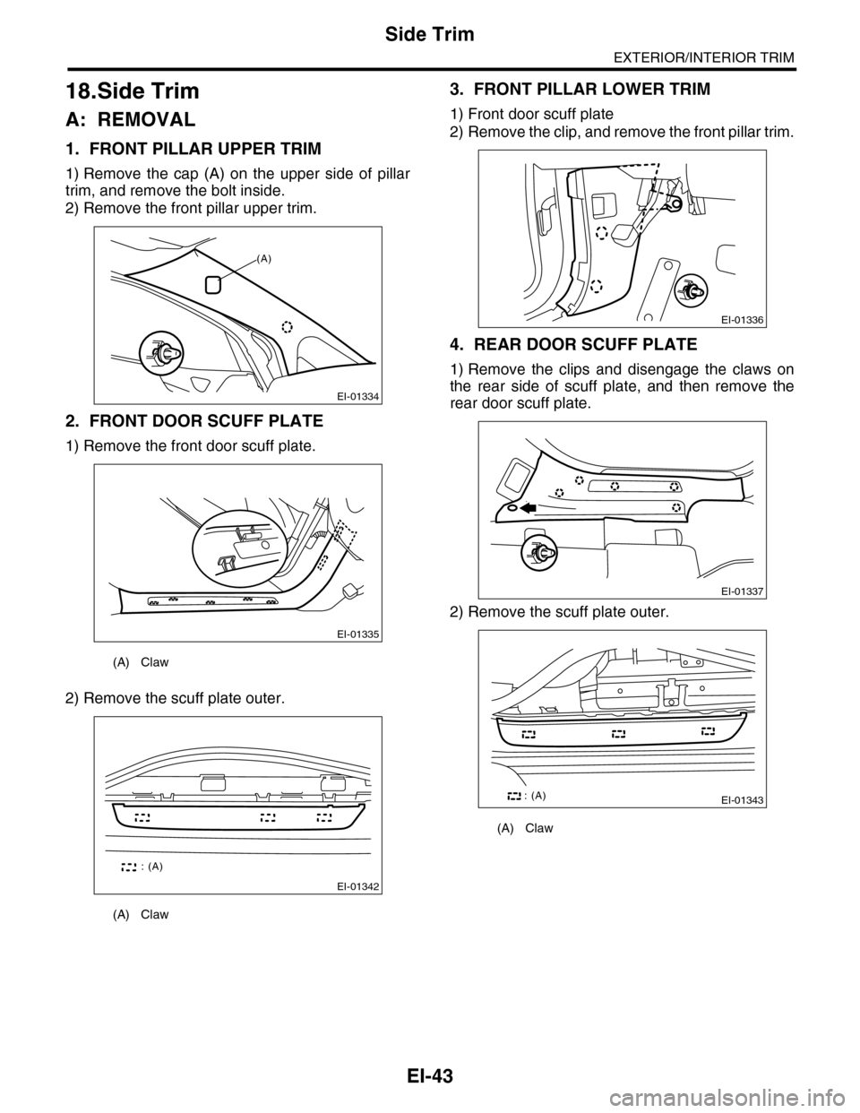
1. FRONT PILLAR UPPER TRIM
1) Remove the cap (A) on the upper side of pillar
trim, and remove the bolt inside.
2) Remove the front pillar upper trim.
2. FRONT DOOR SCUFF PLATE
1) Remove the front door scuff plate.
2) Remove the scuff plate outer.
3. FRONT PILLAR LOWER TRIM
1) Front door scuff plate
2) Remove the clip, and remove the front pillar trim.
4. REAR DOOR SCUFF PLATE
1) Remove the clips and disengage the claws on
the rear side of scuff plate, and then remove the
rear door scuff plate.
2) Remove the scuff plate outer.
(A) Claw
(A) Claw
EI-01334
(A)
EI-01335
EI-01342
: (A)
(A) Claw
EI-01336
EI-01337
EI-01343: (A)
Page 286 of 2453

EI-44
Side Trim
EXTERIOR/INTERIOR TRIM
5. CENTER PILLAR LOWER TRIM
1) Remove the front door scuff plate.
2) Remove the rear door scuff plate.
3) Remove the clip, and remove the center pillar
lower trim.
6. CENTER PILLAR UPPER TRIM
1) When removing the parts of passenger’s side,
disconnect the ground cable from battery and wait
for at least 20 seconds before starting work.
2) Remove the front door scuff plate.
3) Remove the rear door scuff plate.
4) Remove the center pillar lower trim.
5) Turn over the floor mat to remove the seat belt
lower anchor bolt.
6) Disconnect the connector of belt tension sensor
on passenger’s side.
7) Remove the cap (A) on the upper side of pillar
trim, and remove the bolt inside.
8) Remove the clip, and remove the center pillar
upper trim.
B: INSTALLATION
Install each side trim in the reverse order of remov-
al.
NOTE:
When installing the side trim, make sure that the
clips and hooks match the holes of vehicle body be-
fore pushing the parts.
EI-01338
EI-01341
EI-01340
EI-01339
(A)
Page 287 of 2453
EI-45
Rear Quarter Trim
EXTERIOR/INTERIOR TRIM
19.Rear Quarter Trim
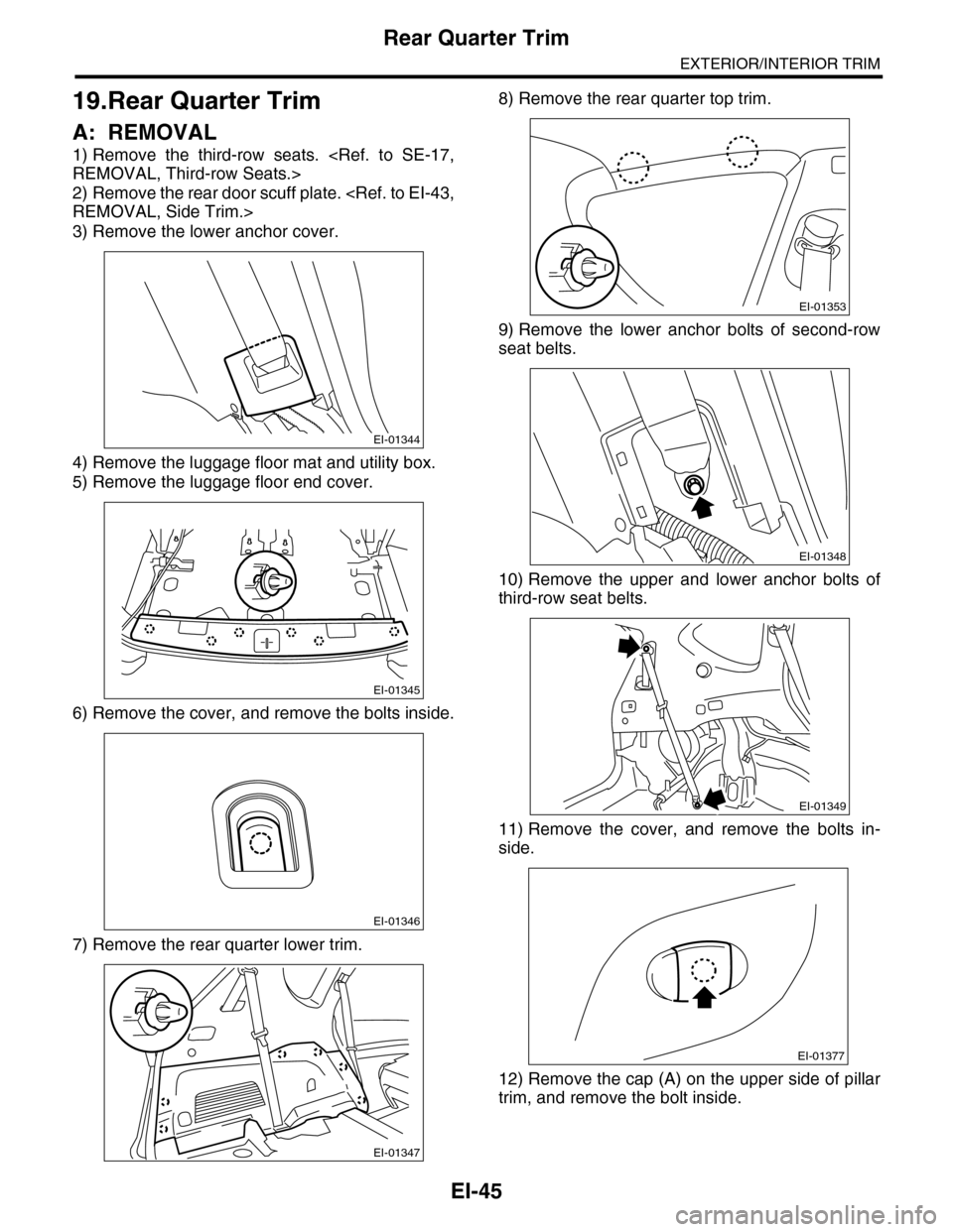
A: REMOVAL
1) Remove the third-row seats.
REMOVAL, Third-row Seats.>
2) Remove the rear door scuff plate.
REMOVAL, Side Trim.>
3) Remove the lower anchor cover.
4) Remove the luggage floor mat and utility box.
5) Remove the luggage floor end cover.
6) Remove the cover, and remove the bolts inside.
7) Remove the rear quarter lower trim.
8) Remove the rear quarter top trim.
9) Remove the lower anchor bolts of second-row
seat belts.
10) Remove the upper and lower anchor bolts of
third-row seat belts.
11) Remove the cover, and remove the bolts in-
side.
12) Remove the cap (A) on the upper side of pillar
trim, and remove the bolt inside.
EI-01344
EI-01345
EI-01346
EI-01347
EI-01353
EI-01348
EI-01349
EI-01377
Page 289 of 2453
EI-47
Floor Mat
EXTERIOR/INTERIOR TRIM
20.Floor Mat
A: REMOVAL
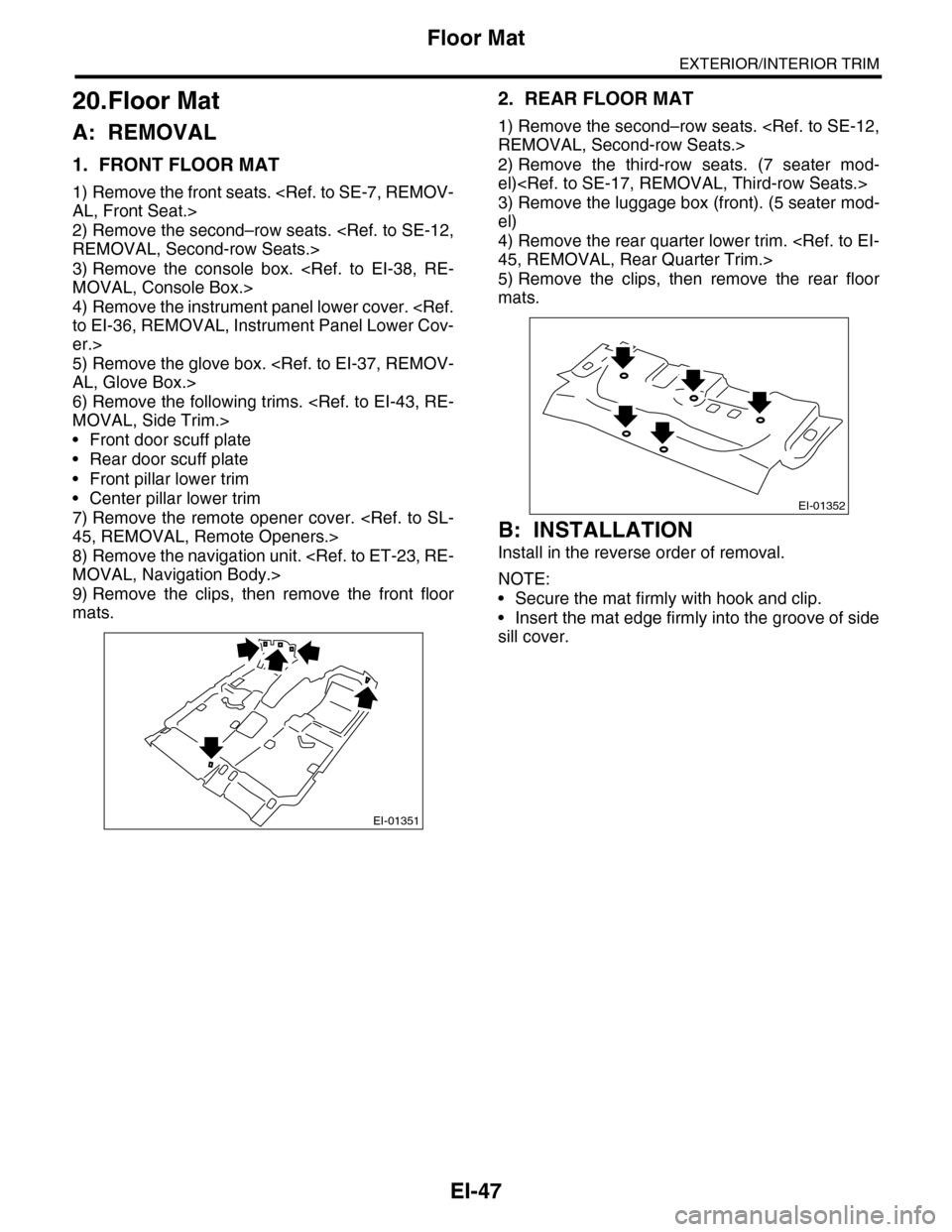
1. FRONT FLOOR MAT
1) Remove the front seats.
AL, Front Seat.>
2) Remove the second–row seats.
REMOVAL, Second-row Seats.>
3) Remove the console box.
MOVAL, Console Box.>
4) Remove the instrument panel lower cover.
to EI-36, REMOVAL, Instrument Panel Lower Cov-
er.>
5) Remove the glove box.
AL, Glove Box.>
6) Remove the following trims.
MOVAL, Side Trim.>
•Front door scuff plate
•Rear door scuff plate
•Front pillar lower trim
•Center pillar lower trim
7) Remove the remote opener cover.
45, REMOVAL, Remote Openers.>
8) Remove the navigation unit.
MOVAL, Navigation Body.>
9) Remove the clips, then remove the front floor
mats.
2. REAR FLOOR MAT
1) Remove the second–row seats.
REMOVAL, Second-row Seats.>
2) Remove the third-row seats. (7 seater mod-
el)
3) Remove the luggage box (front). (5 seater mod-
el)
4) Remove the rear quarter lower trim.
45, REMOVAL, Rear Quarter Trim.>
5) Remove the clips, then remove the rear floor
mats.
B: INSTALLATION
Install in the reverse order of removal.
NOTE:
•Secure the mat firmly with hook and clip.
•Insert the mat edge firmly into the groove of side
sill cover.
EI-01351
EI-01352
Page 298 of 2453
GW-3
General Description
GLASS/WINDOWS/MIRRORS
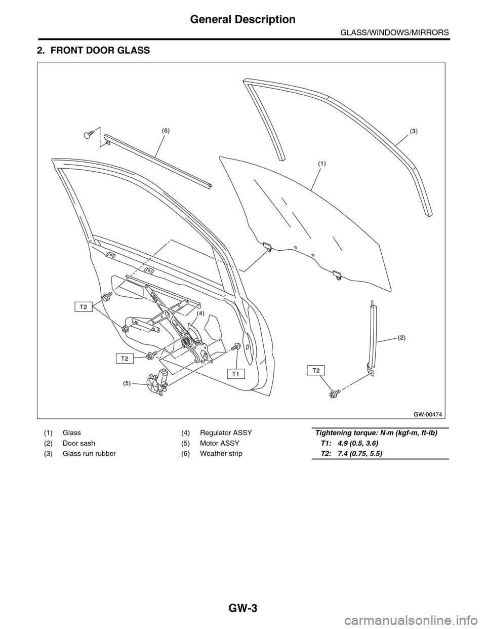
2. FRONT DOOR GLASS
(1) Glass (4) Regulator ASSYTightening torque: N·m (kgf-m, ft-lb)
(2) Door sash (5) Motor ASSYT1: 4.9 (0.5, 3.6)
(3) Glass run rubber (6) Weather stripT2: 7.4 (0.75, 5.5)
Page 299 of 2453
GW-4
General Description
GLASS/WINDOWS/MIRRORS
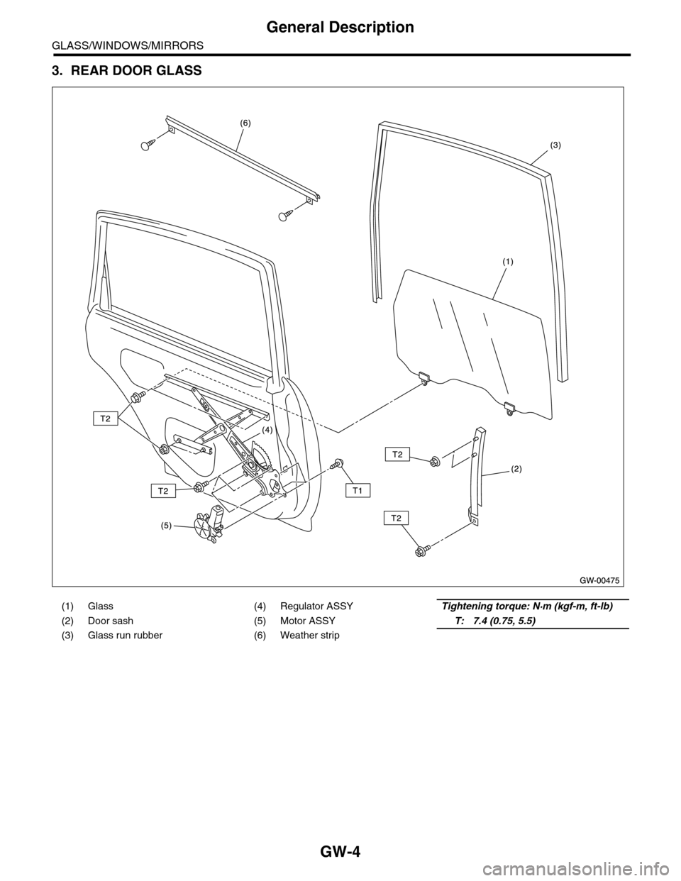
3. REAR DOOR GLASS
(1) Glass (4) Regulator ASSYTightening torque: N·m (kgf-m, ft-lb)
(2) Door sash (5) Motor ASSYT: 7.4 (0.75, 5.5)
(3) Glass run rubber (6) Weather strip