Page 405 of 2453
AC(diag)-28
Diagnostic Procedure for Actuators
HVAC SYSTEM (AUTO A/C) (DIAGNOSTICS)
C: AIR MIX DOOR ACTUATOR
TROUBLE SYMPTOM:
Outlet air temperature does not change.
WIRING DIAGRAM:
AC-01340
B2353412 891011 12 13 14 15 16567
B282A:
B283B282
B23567
B:A:
51
1345726
AUTO A/CCONTROL MODULE
PA S S E N G E R ' S A I R M I XDOOR ACTUATOR
B3907653
DRIVER'S AIR MIXDOOR ACTUATOR
B390
A15B8A4B22A8B9A12B21
B283B:
1234567891014151617181920212223111213242526
13
Page 406 of 2453

AC(diag)-29
Diagnostic Procedure for Actuators
HVAC SYSTEM (AUTO A/C) (DIAGNOSTICS)
Step Check Yes No
1CHECK POWER SUPPLY FOR AIR MIX
DOOR ACTUATOR POSITION SWITCH.
1) Turn the ignition switch to OFF.
2) Disconnect the air mix door actuator con-
nector.
3) Turn the ignition switch and AUTO switch to
ON.
4) Measure the voltage between auto A/C
control module connector terminals.
Connector & terminal
(B282) No. 8 (+) — (B282) No. 15 (–):
Is the voltage approx. 5 V? Go to step 2.Replace the auto
A/C control mod-
ule.
32, REMOVAL,
Control Unit (Auto
A/C Model).>
2CHECK POWER SUPPLY FOR AIR MIX
DOOR ACTUATOR.
Measure the voltage between auto A/C control
module connector and chassis ground after
turning the temperature control dial to maxi-
mum COOL position.
Connector & terminal
Driver’s side
(B283) No. 22 (+) — Chassis ground (–):
Passenger’s side
(B283) No. 21 (+) — Chassis ground (–):
Is the voltage 8 V (at normal
temperature)?
Go to step 3.Replace the auto
A/C control mod-
ule.
32, REMOVAL,
Control Unit (Auto
A/C Model).>
3CHECK POWER SUPPLY FOR AIR MIX
DOOR ACTUATOR.
Measure the voltage between auto A/C control
module connector and chassis ground after
turning the temperature control dial to maxi-
mum HOT position.
Connector & terminal
Driver’s side
(B283) No. 9 (+) — Chassis ground (–):
Passenger’s side
(B283) No. 4 (+) — Chassis ground (–):
Is the voltage 8 V (at normal
temperature)?
Go to step 4.Replace the auto
A/C control mod-
ule.
32, REMOVAL,
Control Unit (Auto
A/C Model).>
4CHECK HARNESS BETWEEN AUTO A/C
CONTROL MODULE AND AIR MIX DOOR
ACTUATOR.
1) Turn the A/C and ignition switch to OFF.
2) Disconnect the auto A/C control module
connector.
3) Measure the resistance between auto A/C
control module and air mix door actuator con-
nector.
Connector & terminal
Driver’s side
(B390) No. 1 — (B282) No. 15:
(B390) No. 3 — (B282) No. 8:
(B390) No. 5 — (B282) No. 12:
(B390) No. 6 — (B283) No. 9:
(B390) No. 7 — (B283) No. 22:
Passenger’s side
(B235) No. 1 — (B282) No. 8:
(B235) No. 3 — (B282) No. 15:
(B235) No. 5 — (B282) No. 4:
(B235) No. 7 — (B283) No. 8:
(B235) No. 6 — (B283) No. 21:
Is the resistance less than 1
Ω?
Go to step 5.Repair the har-
ness between auto
A/C control mod-
ule and air mix
door actuator.
Page 407 of 2453
AC(diag)-30
Diagnostic Procedure for Actuators
HVAC SYSTEM (AUTO A/C) (DIAGNOSTICS)
5CHECK AIR MIX DOOR ACTUATOR POSI-
TION SWITCH SIGNAL.
1) Connect the connector of auto A/C control
module and air mix door actuator.
2) Turn the ignition switch and AUTO switch to
ON.
3) Check the voltage between auto A/C con-
trol module connector terminals while chang-
ing the setting temperature between maximum
COOL and maximum HOT.
Connector & terminal
Driver’s side
(B282) No. 12 (+) — (B282) No. 15 (–):
Passenger’s side
(B282) No. 4 (+) — (B282) No. 15 (–):
Does the voltage change
between 1 V (Max. HOT) and 4
V (Max. COOL)?
Go to step 6.Replace the air
mix door actuator.
REMOVAL, Actua-
tor.>
6CHECK POOR CONTACT.
Check poor contact of auto A/C control module
and connector.
Is there poor contact in con-
nector?
Repair the con-
nector.
Replace the auto
A/C control mod-
ule.
32, REMOVAL,
Control Unit (Auto
A/C Model).>
Step Check Yes No
Page 414 of 2453
AC(diag)-37
Diagnostic Procedure for Sensors
HVAC SYSTEM (AUTO A/C) (DIAGNOSTICS)
D: SUNLOAD SENSOR
TROUBLE SYMPTOM:
•Sensor identifies that sunlight is at maximum. Then, A/C system is controlled to COOL side.
•Sensor identifies that sunlight is at minimum. Then, A/C system is controlled to HOT side.
NOTE:
When the sunload sensor check is performed indoors or in the shade, it could be diagnosed as having an
open circuit. Always check the sunload sensor with the sun shining on it.
WIRING DIAGRAM:
AC-00832
A:B282
12345678910 11 12 13 14 15 16
i51
A:B282
A8A6
21
i3
B38
i51
12
AUTO A/C CONTROL MODULE
32
1234 5678910 11 12 13 14 15 16 17 18 19 20
B38
SUNLOADSENSOR
Page 416 of 2453

AC(diag)-39
Diagnostics with Phenomenon
HVAC SYSTEM (AUTO A/C) (DIAGNOSTICS)
9. Diagnostics with Phenomenon
A: INSPECTION
Symptom Problem parts
A/C system fails to operate.
•Fuse (M/B No. 15, F/B No. 7, 22, 31)
•Connector (Poor contact)
•Ground
•Auto A/C control module
•Blower fan motor
•Blower fan relay
•A/C relay
•Compressor (Magnet clutch)
•Evaporator sensor
Fuse is blown out.•Fuse (M/B No. 8, F/B No. 22, 31)
•Connector (Poor contact)
Illumination cannot dim.
•Fuse (M/B No. 8, F/B No. 22, 31)
•Connector (Poor contact)
•Illumination control switch
•Auto A/C control module
•Body integrated unit
Blower fan does not rotate or fan speed cannot be controlled.
•Fuse (F/B No. 22, 27, 28)
•Connector (Poor contact)
•Ground
•Auto A/C control module
•Blower fan motor
•Blower fan relay
•Power transistor or blower resistor
Unable to switch suction vents.
•Connector (Poor contact)
•Auto A/C control module
•Intake door actuator
Unable to switch blow vents.
•Connector (Poor contact)
•Auto A/C control module
•Mode door actuator
The compar tment temperature does not rise. (Warm air not
emitted.)
•Connector (Poor contact)
•Auto A/C control module
•Air mix door actuator
•In-vehicle sensor, ambient sensor, evaporator sensor and
sunload sensor
•In-vehicle sensor aspirator hose
•Aspirator body
The compar tment temperature does not lower. (Cold air not
emitted.)
•Connector (Poor contact)
•Auto A/C control module
•Air mix door actuator
•A/C relay
•Compressor (Magnet clutch)
•Radiator fan motor
•Radiator fan relay
•In-vehicle sensor, ambient sensor, evaporator sensor and
sunload sensor
•In-vehicle sensor aspirator hose
•Aspirator body
Compartment temperature is higher or lower than setting tem-
perature.
•Auto A/C control module
•Air mix door actuator
•In-vehicle sensor, ambient sensor, evaporator sensor and
sunload sensor
•In-vehicle sensor aspirator hose
•Aspirator body
Page 417 of 2453
AC(diag)-40
Diagnostics with Phenomenon
HVAC SYSTEM (AUTO A/C) (DIAGNOSTICS)
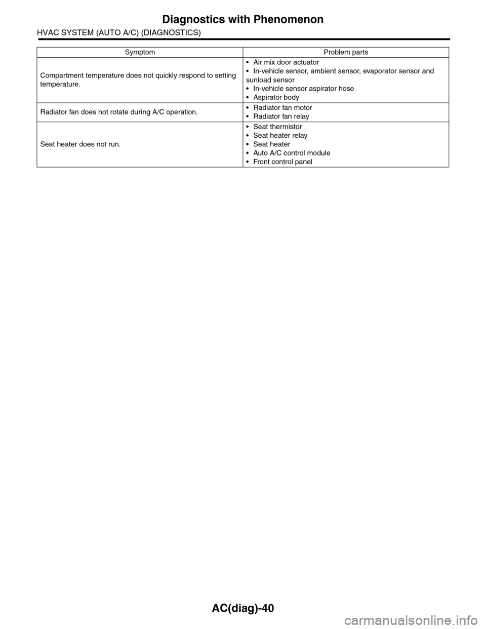
Compartment temperature does not quickly respond to setting
temperature.
•Air mix door actuator
•In-vehicle sensor, ambient sensor, evaporator sensor and
sunload sensor
•In-vehicle sensor aspirator hose
•Aspirator body
Radiator fan does not rotate during A/C operation.•Radiator fan motor
•Radiator fan relay
Seat heater does not run.
•Seat thermistor
•Seat heater relay
•Seat heater
•Auto A/C control module
•Front control panel
Symptom Problem parts
Page 441 of 2453
IDI-2
General Description
INSTRUMENTATION/DRIVER INFO
1. General Description
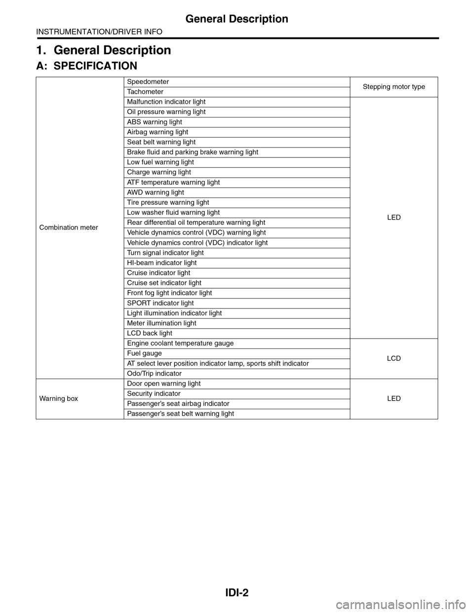
A: SPECIFICATION
Combination meter
SpeedometerStepping motor typeTa c h o m e t e r
Malfunction indicator light
LED
Oil pressure warning light
ABS warning light
Airbag warning light
Seat belt warning light
Brake fluid and parking brake warning light
Low fuel warning light
Charge warning light
AT F t e m p e r a t u r e w a r n i n g l i g h t
AW D war n in g l i gh t
Tire pressure warning light
Low washer fluid warning light
Rear differential oil temperature warning light
Ve h i c l e d y n a m i c s c o n t r o l ( V D C ) w a r n i n g l i g h t
Ve h i c l e d y n a m i c s c o n t r o l ( V D C ) i n d i c a t o r l i g h t
Tu r n s i g n a l i n d i c a t o r l i g h t
HI-beam indicator light
Cruise indicator light
Cruise set indicator light
Fr o nt fog li g ht i nd i ca to r li g ht
SPORT indicator light
Light illumination indicator light
Meter illumination light
LCD back light
Engine coolant temperature gauge
LCDFuel gauge
AT s e l e c t l e v e r p o s i t i o n i n d i c a t o r l a m p , s p o r t s s h i f t i n d i c a t o r
Odo/Trip indicator
Wa r ni n g b ox
Door open warning light
LEDSecurity indicator
Passenger’s seat airbag indicator
Passenger’s seat belt war ning light
Page 460 of 2453
LAN(diag)-4
Check List for Interview
LAN SYSTEM (DIAGNOSTICS)
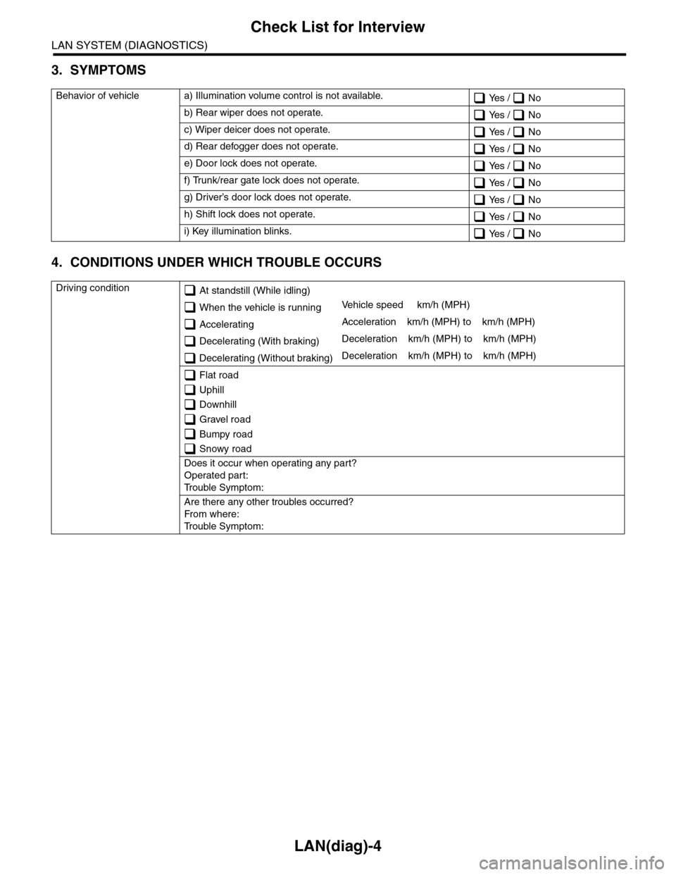
3. SYMPTOMS
4. CONDITIONS UNDER WHICH TROUBLE OCCURS
Behavior of vehicle a) Illumination volume control is not available. Yes / No
b) Rear wiper does not operate. Yes / No
c) Wiper deicer does not operate. Yes / No
d) Rear defogger does not operate. Yes / No
e) Door lock does not operate. Yes / No
f) Trunk/rear gate lock does not operate. Yes / No
g) Driver’s door lock does not operate. Yes / No
h) Shift lock does not operate. Yes / No
i) Key illumination blinks. Yes / No
Driving condition At standstill (While idling)
When the vehicle is runningVe h i c l e s p e e d k m / h ( M P H )
AcceleratingAcceleration km/h (MPH) to km/h (MPH)
Decelerating (With braking)Deceleration km/h (MPH) to km/h (MPH)
Decelerating (Without braking)Deceleration km/h (MPH) to km/h (MPH)
Flat road
Uphill
Downhill
Gravel road
Bumpy road
Snowy road
Does it occur when operating any part?
Operated part:
Tr o u b l e S y m p t o m :
Are there any other troubles occurred?
Fr o m wh er e :
Tr o u b l e S y m p t o m :