Page 1409 of 2453
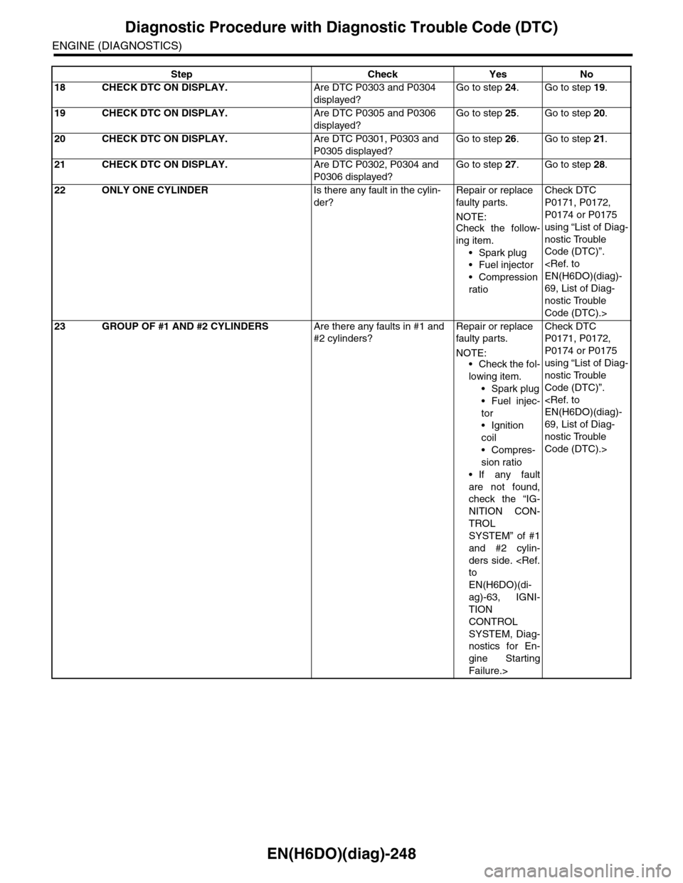
EN(H6DO)(diag)-248
Diagnostic Procedure with Diagnostic Trouble Code (DTC)
ENGINE (DIAGNOSTICS)
18 CHECK DTC ON DISPLAY.Are DTC P0303 and P0304
displayed?
Go to step 24.Go to step 19.
19 CHECK DTC ON DISPLAY.Are DTC P0305 and P0306
displayed?
Go to step 25.Go to step 20.
20 CHECK DTC ON DISPLAY.Are DTC P0301, P0303 and
P0305 displayed?
Go to step 26.Go to step 21.
21 CHECK DTC ON DISPLAY.Are DTC P0302, P0304 and
P0306 displayed?
Go to step 27.Go to step 28.
22 ONLY ONE CYLINDERIs there any fault in the cylin-
der?
Repair or replace
faulty par ts.
NOTE:Check the follow-
ing item.
•Spark plug
•Fuel injector
•Compression
ratio
Check DTC
P0171, P0172,
P0174 or P0175
using “List of Diag-
nostic Trouble
Code (DTC)”.
EN(H6DO)(diag)-
69, List of Diag-
nostic Trouble
Code (DTC).>
23 GROUP OF #1 AND #2 CYLINDERSAre there any faults in #1 and
#2 cylinders?
Repair or replace
faulty par ts.
NOTE:•Check the fol-
lowing item.
•Spark plug
•Fuel injec-
tor
•Ignition
coil
•Compres-
sion ratio
•If any fault
are not found,
check the “IG-
NITION CON-
TROL
SYSTEM” of #1
and #2 cylin-
ders side.
to
EN(H6DO)(di-
ag)-63, IGNI-
TION
CONTROL
SYSTEM, Diag-
nostics for En-
gine Starting
Failure.>
Check DTC
P0171, P0172,
P0174 or P0175
using “List of Diag-
nostic Trouble
Code (DTC)”.
EN(H6DO)(diag)-
69, List of Diag-
nostic Trouble
Code (DTC).>
Step Check Yes No
Page 1410 of 2453
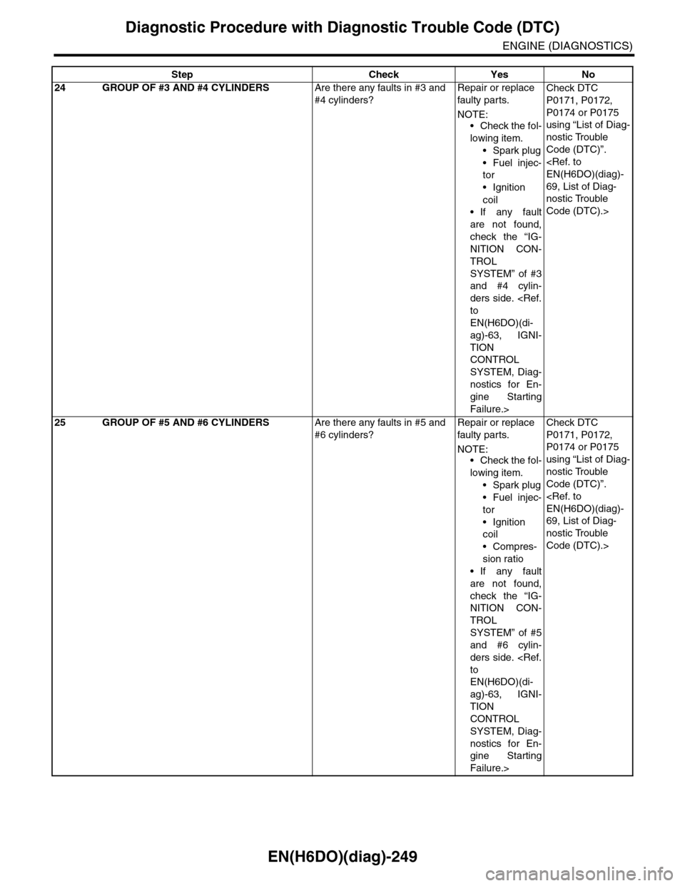
EN(H6DO)(diag)-249
Diagnostic Procedure with Diagnostic Trouble Code (DTC)
ENGINE (DIAGNOSTICS)
24 GROUP OF #3 AND #4 CYLINDERSAre there any faults in #3 and
#4 cylinders?
Repair or replace
faulty par ts.
NOTE:
•Check the fol-
lowing item.
•Spark plug
•Fuel injec-
tor
•Ignition
coil
•If any fault
are not found,
check the “IG-
NITION CON-
TROL
SYSTEM” of #3
and #4 cylin-
ders side.
to
EN(H6DO)(di-
ag)-63, IGNI-
TION
CONTROL
SYSTEM, Diag-
nostics for En-
gine Starting
Failure.>
Check DTC
P0171, P0172,
P0174 or P0175
using “List of Diag-
nostic Trouble
Code (DTC)”.
EN(H6DO)(diag)-
69, List of Diag-
nostic Trouble
Code (DTC).>
25 GROUP OF #5 AND #6 CYLINDERSAre there any faults in #5 and
#6 cylinders?
Repair or replace
faulty par ts.
NOTE:•Check the fol-
lowing item.
•Spark plug
•Fuel injec-
tor
•Ignition
coil
•Compres-
sion ratio
•If any fault
are not found,
check the “IG-
NITION CON-
TROL
SYSTEM” of #5
and #6 cylin-
ders side.
to
EN(H6DO)(di-
ag)-63, IGNI-
TION
CONTROL
SYSTEM, Diag-
nostics for En-
gine Starting
Failure.>
Check DTC
P0171, P0172,
P0174 or P0175
using “List of Diag-
nostic Trouble
Code (DTC)”.
EN(H6DO)(diag)-
69, List of Diag-
nostic Trouble
Code (DTC).>
Step Check Yes No
Page 1411 of 2453
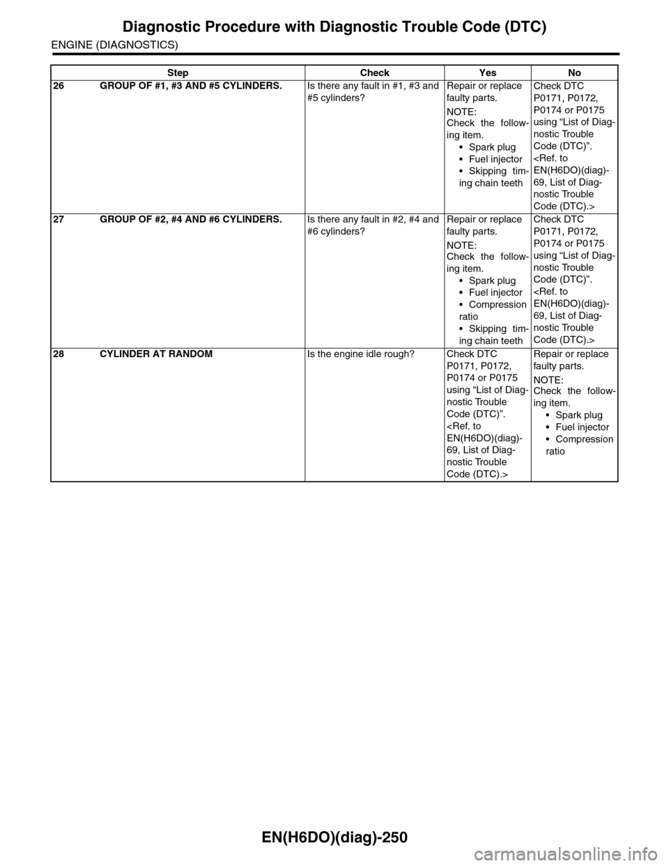
EN(H6DO)(diag)-250
Diagnostic Procedure with Diagnostic Trouble Code (DTC)
ENGINE (DIAGNOSTICS)
26 GROUP OF #1, #3 AND #5 CYLINDERS.Is there any fault in #1, #3 and
#5 cylinders?
Repair or replace
faulty par ts.
NOTE:
Check the follow-
ing item.
•Spark plug
•Fuel injector
•Skipping tim-
ing chain teeth
Check DTC
P0171, P0172,
P0174 or P0175
using “List of Diag-
nostic Trouble
Code (DTC)”.
EN(H6DO)(diag)-
69, List of Diag-
nostic Trouble
Code (DTC).>
27 GROUP OF #2, #4 AND #6 CYLINDERS.Is there any fault in #2, #4 and
#6 cylinders?
Repair or replace
faulty par ts.
NOTE:Check the follow-
ing item.
•Spark plug
•Fuel injector
•Compression
ratio
•Skipping tim-
ing chain teeth
Check DTC
P0171, P0172,
P0174 or P0175
using “List of Diag-
nostic Trouble
Code (DTC)”.
EN(H6DO)(diag)-
69, List of Diag-
nostic Trouble
Code (DTC).>
28 CYLINDER AT RANDOMIs the engine idle rough? Check DTC
P0171, P0172,
P0174 or P0175
using “List of Diag-
nostic Trouble
Code (DTC)”.
EN(H6DO)(diag)-
69, List of Diag-
nostic Trouble
Code (DTC).>
Repair or replace
faulty par ts.
NOTE:Check the follow-
ing item.
•Spark plug
•Fuel injector
•Compression
ratio
Step Check Yes No
Page 1430 of 2453
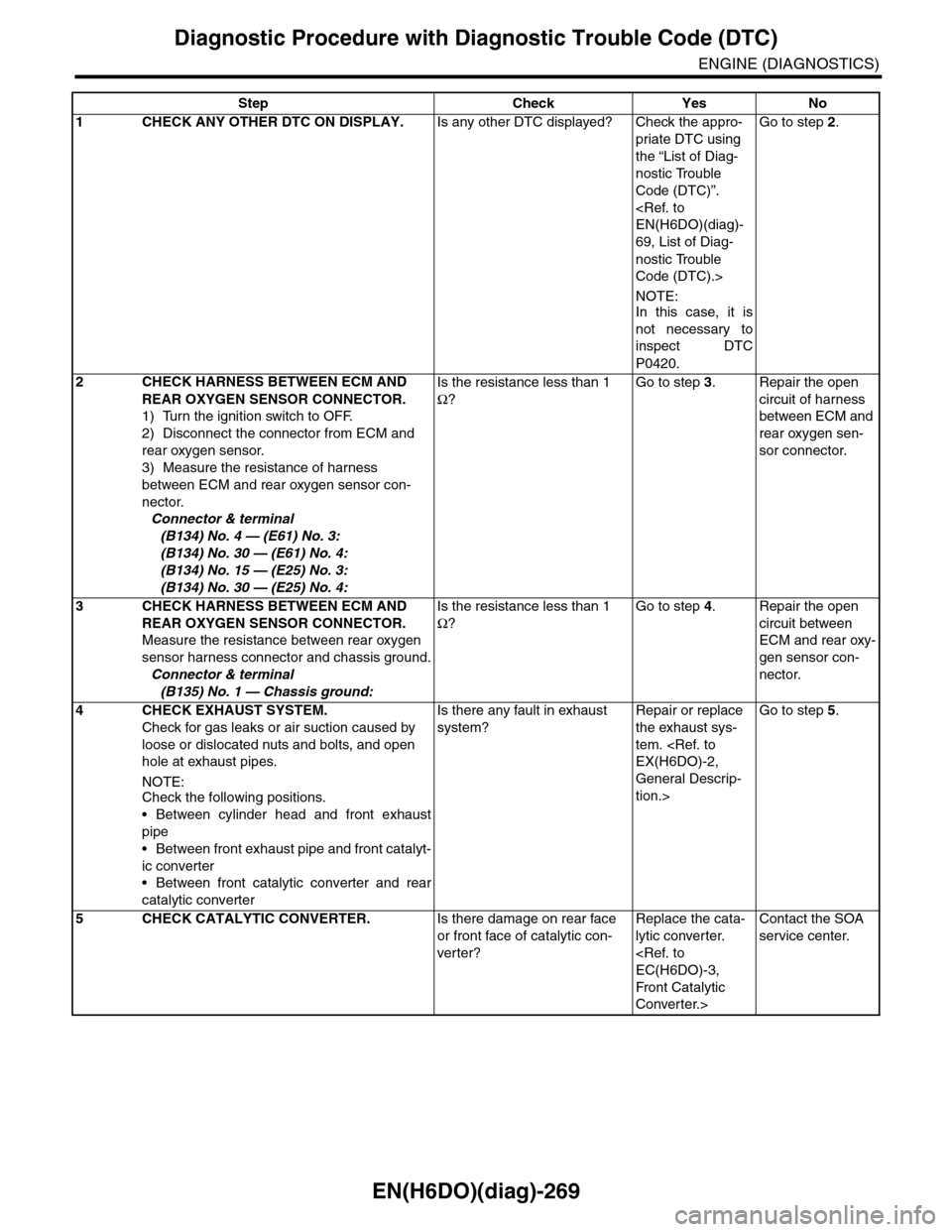
EN(H6DO)(diag)-269
Diagnostic Procedure with Diagnostic Trouble Code (DTC)
ENGINE (DIAGNOSTICS)
Step Check Yes No
1CHECK ANY OTHER DTC ON DISPLAY.Is any other DTC displayed? Check the appro-
priate DTC using
the “List of Diag-
nostic Trouble
Code (DTC)”.
EN(H6DO)(diag)-
69, List of Diag-
nostic Trouble
Code (DTC).>
NOTE:In this case, it is
not necessary to
inspect DTC
P0420.
Go to step 2.
2CHECK HARNESS BETWEEN ECM AND
REAR OXYGEN SENSOR CONNECTOR.
1) Turn the ignition switch to OFF.
2) Disconnect the connector from ECM and
rear oxygen sensor.
3) Measure the resistance of harness
between ECM and rear oxygen sensor con-
nector.
Connector & terminal
(B134) No. 4 — (E61) No. 3:
(B134) No. 30 — (E61) No. 4:
(B134) No. 15 — (E25) No. 3:
(B134) No. 30 — (E25) No. 4:
Is the resistance less than 1
Ω?
Go to step 3.Repair the open
circuit of harness
between ECM and
rear oxygen sen-
sor connector.
3CHECK HARNESS BETWEEN ECM AND
REAR OXYGEN SENSOR CONNECTOR.
Measure the resistance between rear oxygen
sensor harness connector and chassis ground.
Connector & terminal
(B135) No. 1 — Chassis ground:
Is the resistance less than 1
Ω?
Go to step 4.Repair the open
circuit between
ECM and rear oxy-
gen sensor con-
nector.
4 CHECK EXHAUST SYSTEM.
Check for gas leaks or air suction caused by
loose or dislocated nuts and bolts, and open
hole at exhaust pipes.
NOTE:Check the following positions.
•Between cylinder head and front exhaust
pipe
•Between front exhaust pipe and front catalyt-
ic converter
•Between front catalytic converter and rear
catalytic converter
Is there any fault in exhaust
system?
Repair or replace
the exhaust sys-
tem.
EX(H6DO)-2,
General Descrip-
tion.>
Go to step 5.
5CHECK CATALYTIC CONVERTER.Is there damage on rear face
or front face of catalytic con-
ver ter?
Replace the cata-
lytic converter.
EC(H6DO)-3,
Front Catalytic
Converter.>
Contact the SOA
service center.
Page 1558 of 2453
EX(H6DO)-4
Front Exhaust Pipe
EXHAUST
2. Front Exhaust Pipe
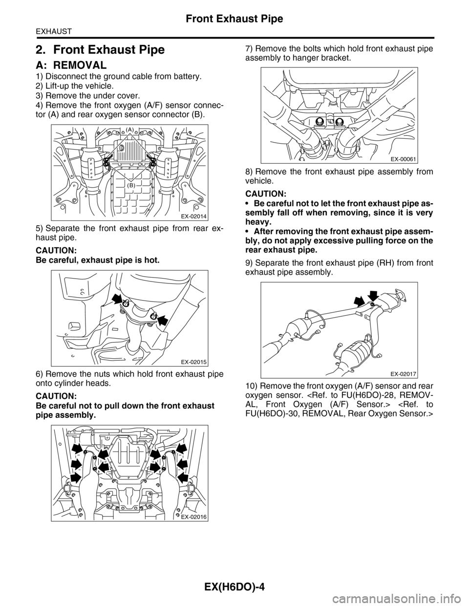
A: REMOVAL
1) Disconnect the ground cable from battery.
2) Lift-up the vehicle.
3) Remove the under cover.
4) Remove the front oxygen (A/F) sensor connec-
tor (A) and rear oxygen sensor connector (B).
5) Separate the front exhaust pipe from rear ex-
haust pipe.
CAUTION:
Be careful, exhaust pipe is hot.
6) Remove the nuts which hold front exhaust pipe
onto cylinder heads.
CAUTION:
Be careful not to pull down the front exhaust
pipe assembly.
7) Remove the bolts which hold front exhaust pipe
assembly to hanger bracket.
8) Remove the front exhaust pipe assembly from
vehicle.
CAUTION:
•Be careful not to let the front exhaust pipe as-
sembly fall off when removing, since it is very
heavy.
•After removing the front exhaust pipe assem-
bly, do not apply excessive pulling force on the
rear exhaust pipe.
9) Separate the front exhaust pipe (RH) from front
exhaust pipe assembly.
10) Remove the front oxygen (A/F) sensor and rear
oxygen sensor.
AL, Front Oxygen (A/F) Sensor.>
FU(H6DO)-30, REMOVAL, Rear Oxygen Sensor.>
EX-02014
(A)
(B)
EX-02015
EX-02016
EX-00061
EX-02017
Page 1559 of 2453
EX(H6DO)-5
Front Exhaust Pipe
EXHAUST
B: INSTALLATION
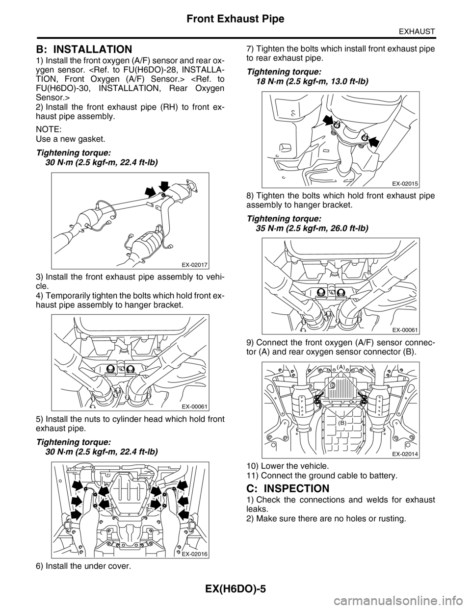
1) Install the front oxygen (A/F) sensor and rear ox-
ygen sensor.
TION, Front Oxygen (A/F) Sensor.>
FU(H6DO)-30, INSTALLATION, Rear Oxygen
Sensor.>
2) Install the front exhaust pipe (RH) to front ex-
haust pipe assembly.
NOTE:
Use a new gasket.
Tightening torque:
30 N·m (2.5 kgf-m, 22.4 ft-lb)
3) Install the front exhaust pipe assembly to vehi-
cle.
4) Temporarily tighten the bolts which hold front ex-
haust pipe assembly to hanger bracket.
5) Install the nuts to cylinder head which hold front
exhaust pipe.
Tightening torque:
30 N·m (2.5 kgf-m, 22.4 ft-lb)
6) Install the under cover.
7) Tighten the bolts which install front exhaust pipe
to rear exhaust pipe.
Tightening torque:
18 N·m (2.5 kgf-m, 13.0 ft-lb)
8) Tighten the bolts which hold front exhaust pipe
assembly to hanger bracket.
Tightening torque:
35 N·m (2.5 kgf-m, 26.0 ft-lb)
9) Connect the front oxygen (A/F) sensor connec-
tor (A) and rear oxygen sensor connector (B).
10) Lower the vehicle.
11) Connect the ground cable to battery.
C: INSPECTION
1) Check the connections and welds for exhaust
leaks.
2) Make sure there are no holes or rusting.
EX-02017
EX-00061
EX-02016
EX-02015
EX-00061
EX-02014
(A)
(B)
Page 1574 of 2453
FU(H6DO)-13
Intake Manifold
FUEL INJECTION (FUEL SYSTEMS)
14) Remove the bolts which hold fuel injector pipe
LH to cylinder head.
15) Remove the fuel pipe protector RH.
16) Remove the engine harness from fuel injector
pipe RH.
17) Remove the bolts which hold the fuel injector
pipe RH to the cylinder head.
18) Remove the bolts which hold the intake mani-
fold to the cylinder head.
•LH side
•RH side
19) Remove the intake manifold.
B: INSTALLATION
1) Install the intake manifold onto cylinder heads.
NOTE:
Use new O-rings.
Tightening torque:
25 N·m (2.5 kgf-m, 18 ft-lb)
•RH side
•LH side
FU-02118
FU-02119
FU-02120
FU-02121
FU-02122
FU-02122
FU-02121
Page 1575 of 2453
FU(H6DO)-14
Intake Manifold
FUEL INJECTION (FUEL SYSTEMS)
2) Install the bolts which hold fuel injector pipe RH
to cylinder head.
Tightening torque:
19 N·m (1.9 kgf-m, 14 ft-lb)
3) Install the engine harness to fuel injector pipe
RH.
4) Install the fuel pipe protector RH.
Tightening torque:
19 N·m (1.9 kgf-m, 14 ft-lb)
5) Install the bolts which hold fuel injector pipe LH
to cylinder head.
Tightening torque:
19 N·m (1.9 kgf-m, 14 ft-lb)
6) Install the engine harness to fuel injector pipe
LH.
7) Install the fuel pipe protector LH.
Tightening torque:
19 N·m (1.9 kgf-m, 14 ft-lb)
8) Connect the fuel hoses to fuel pipe.
9) Connect the brake booster hose.
10) Connect the PCV hose.
FU-02120
FU-02119
FU-02118
FU-02117
ME-02384
ME-02655
EC-02133