Page 1886 of 2453
ME(H6DO)-20
General Description
MECHANICAL
2. GENERAL TOOL
E: PROCEDURE
It is possible to conduct the following service procedures with engine on vehicle, however, the procedures
described in this section are based on the condition that the engine is removed from vehicle.
•Camshaft
•Cylinder head
18471AA000 FUEL PIPE
ADAPTER
Used for measuring fuel pressure.
42075AG690 FUEL HOSE Used for measuring fuel pressure.
This is a genuine Subaru part.
TOOL NAME REMARKS
Compression gauge Used for measuring compression.
ILLUSTRATION TOOL NUMBER DESCRIPTION REMARKS
Page 1887 of 2453
ME(H6DO)-21
Compression
MECHANICAL
2. Compression
A: INSPECTION
CAUTION:
After warming-up, engine becomes very hot. Be
careful not to burn yourself during measure-
ment.
1) After warming-up the engine, turn the ignition
switch to OFF.
2) Make sure that the battery is fully charged.
3) Release the fuel pressure.
PRESSURE, PROCEDURE, Fuel.>
4) Remove all the spark plugs.
4, REMOVAL, Spark Plug.>
5) Check the starter motor for satisfactory perfor-
mance and operation.
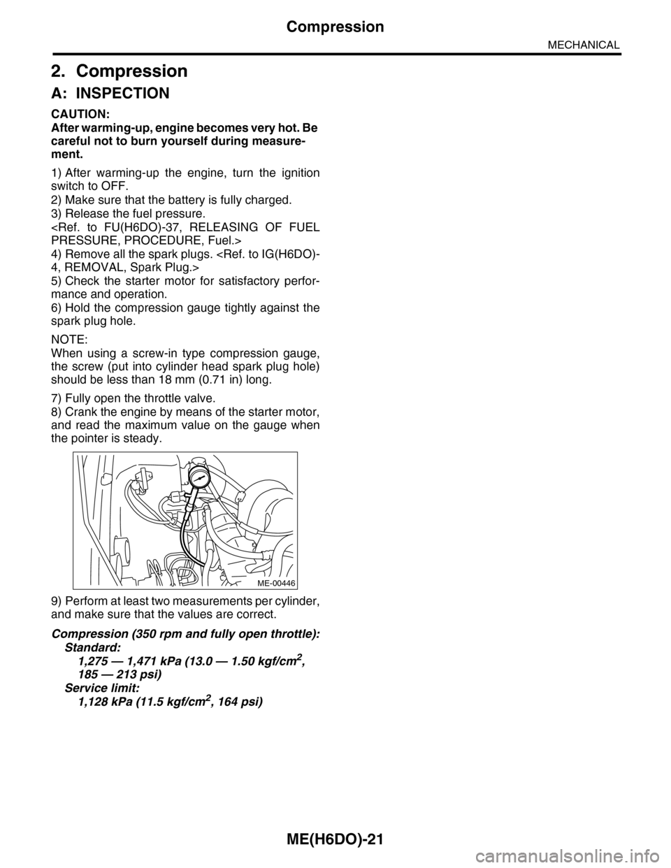
6) Hold the compression gauge tightly against the
spark plug hole.
NOTE:
When using a screw-in type compression gauge,
the screw (put into cylinder head spark plug hole)
should be less than 18 mm (0.71 in) long.
7) Fully open the throttle valve.
8) Crank the engine by means of the starter motor,
and read the maximum value on the gauge when
the pointer is steady.
9) Perform at least two measurements per cylinder,
and make sure that the values are correct.
Compression (350 rpm and fully open throttle):
Standard:
1,275 — 1,471 kPa (13.0 — 1.50 kgf/cm2,
185 — 213 psi)
Service limit:
1,128 kPa (11.5 kgf/cm2, 164 psi)
ME-00446
Page 1890 of 2453
ME(H6DO)-24
Intake Manifold Vacuum
MECHANICAL
5. Intake Manifold Vacuum
A: INSPECTION
1) Idle the engine.
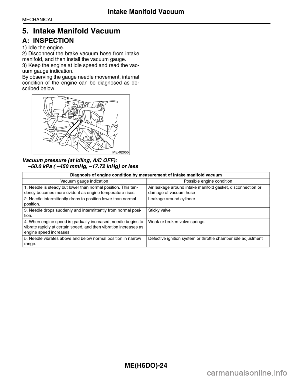
2) Disconnect the brake vacuum hose from intake
manifold, and then install the vacuum gauge.
3) Keep the engine at idle speed and read the vac-
uum gauge indication.
By observing the gauge needle movement, internal
condition of the engine can be diagnosed as de-
scribed below.
Vacuum pressure (at idling, A/C OFF):
–60.0 kPa ( –450 mmHg, –17.72 inHg) or less
ME-02655
Diagnosis of engine condition by measurement of intake manifold vacuum
Va c u u m g a u g e i n d i c a t i o n Po s s i bl e e n g i n e c o n d i t i o n
1. Needle is steady but lower than normal position. This ten-
dency becomes more evident as engine temperature rises.
Air leakage around intake manifold gasket, disconnection or
damage of vacuum hose
2. Needle intermittently drops to position lower than normal
position.
Leakage around cylinder
3. Needle drops suddenly and intermittently from normal posi-
tion.
Sticky valve
4. When engine speed is gradually increased, needle begins to
vibrate rapidly at certain speed, and then vibration increases as
engine speed increases.
Weak or broken valve spr ings
5. Needle vibrates above and below normal position in narrow
range.
Defective ignition system or throttle chamber idle adjustment
Page 1891 of 2453
ME(H6DO)-25
Engine Oil Pressure
MECHANICAL
6. Engine Oil Pressure
A: INSPECTION
1) Remove the oil pressure switch from cylinder
block.
Pressure Switch.>
2) Connect the oil pressure gauge hose to cylinder
block.
3) Connect the ground cable to the battery.
4) Start the engine, and measure the oil pressure.
OIL PRESSURE (at oil temperature of 80°C
(176°F)):
Standard:
135 kPa (1.4 kgf/cm2, 20 psi) or more (at
600 rpm)
500 kPa (5.1 kgf/cm2, 73 psi) or more (at
5,000 rpm)
CAUTION:
•If the oil pressure is out of specification,
check oil pump, oil filter and lubrication line.
Diagnostics Table.>
•If the oil pressure warning light is turned ON
and oil pressure is in specification, replace the
oil pressure switch.
SPECTION, General Diagnostics Table.>
5) After measuring the oil pressure, install the oil
pressure switch.
LATION, Oil Pressure Switch.>
Tightening torque:
25 N·m (2.5 kgf-m, 18 ft-lb)
Page 1893 of 2453
ME(H6DO)-27
Valve Clearance
MECHANICAL
8. Valve Clearance
A: INSPECTION
Inspection and adjustment of valve clearance
should be performed while engine is cold.
1) Set the vehicle on a lift.
2) Remove the collector cover.
3) Disconnect the ground cable from battery.
4) Lift-up the vehicle.
5) Remove the under cover.
6) Lower the vehicle.
7) When inspecting RH side cylinders:
(1) Remove the air intake duct and air cleaner
case.
take Duct.>
Air Cleaner Case.>
(2) Remove the fuel tank protector (RH).
(3) Disconnect the connector of oil pressure
switch.
(4) Remove the ignition coil.
IG(H6DO)-7, REMOVAL, Ignition Coil & Ignitor
Assembly.>
(5) Remove the rocker cover (RH).
8) When inspecting LH side cylinders:
(1) Disconnect the battery cable, and then re-
move the battery and battery carrier.
(2) Disconnect the PCV hose and blow-by hose
from rocker cover (LH).
(3) Remove the fuel pipe protector (LH).
(4) Remove the ignition coil.
IG(H6DO)-7, REMOVAL, Ignition Coil & Ignitor
Assembly.>
(5) Remove the rocker cover (LH).
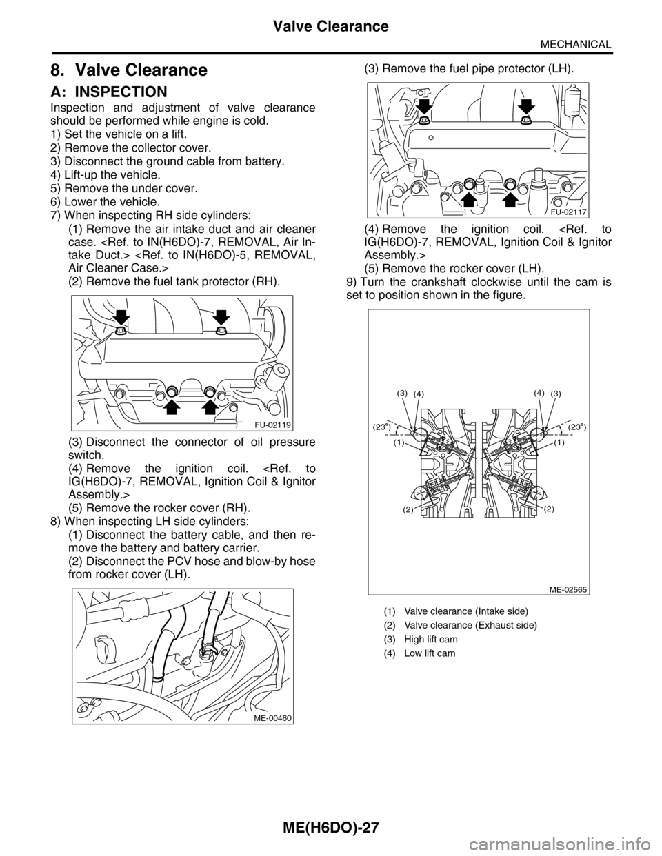
9) Turn the crankshaft clockwise until the cam is
set to position shown in the figure.
FU-02119
ME-00460
(1) Valve clearance (Intake side)
(2) Valve clearance (Exhaust side)
(3) High lift cam
(4) Low lift cam
FU-02117
ME-02565
(4)(3)(3)(4)
(1)
(2)
(1)
(2)
(23 )(23 )
Page 1894 of 2453
ME(H6DO)-28
Valve Clearance
MECHANICAL
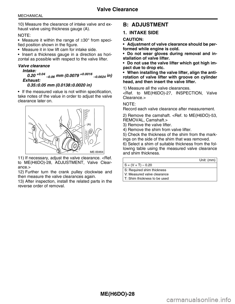
10) Measure the clearance of intake valve and ex-
haust valve using thickness gauge (A).
NOTE:
•Measure it within the range of ±30° from speci-
fied position shown in the figure.
•Measure it in low lift cam for intake side.
•Insert a thickness gauge in a direction as hori-
zontal as possible with respect to the valve lifter.
Valve clearance
Intake:
0.20 +0.04 –0.06 mm (0.0079 +0.0016 –0.0024 in)
Exhaust:
0.35±0.05 mm (0.0138±0.0020 in)
•If the measured value is not within specification,
take notes of the value in order to adjust the valve
clearance later on.
11) If necessary, adjust the valve clearance.
to ME(H6DO)-28, ADJUSTMENT, Valve Clear-
ance.>
12) Further turn the crank pulley clockwise and
then measure the valve clearances again.
13) After inspection, install the related parts in the
reverse order of removal.
B: ADJUSTMENT
1. INTAKE SIDE
CAUTION:
•Adjustment of valve clearance should be per-
formed while engine is cold.
•Do not wear gloves during removal and in-
stallation of valve lifter.
•Do not use the valve lifter which got high im-
pact due to drop etc.
•When installing the valve lifter, align the anti-
rotation of valve lifter with groove on cylinder
head, and then insert the valve lifter.
1) Measure all the valve clearances.
Clearance.>
NOTE:
Record each valve clearance after measurement.
2) Remove the camshaft.
REMOVAL, Camshaft.>
3) Remove the valve lifter.
4) Remove the shim from valve lifter.
5) Check the thickness of the shim from the mark-
ings on the side of the shim that was removed.
6) Select a shim of suitable thickness from the fol-
lowing table using the measured valve clearance
and shim thickness.
(A)
ME-00464
Unit: (mm)
S = (V + T) – 0.20
S: Required shim thickness
V: Measured valve clearance
T: Shim thickness to be used
Page 1920 of 2453
ME(H6DO)-54
Camshaft
MECHANICAL
B: INSTALLATION
1) Apply engine oil to camshaft journals, and install
the camshaft.
2) Install the camshaft cap.
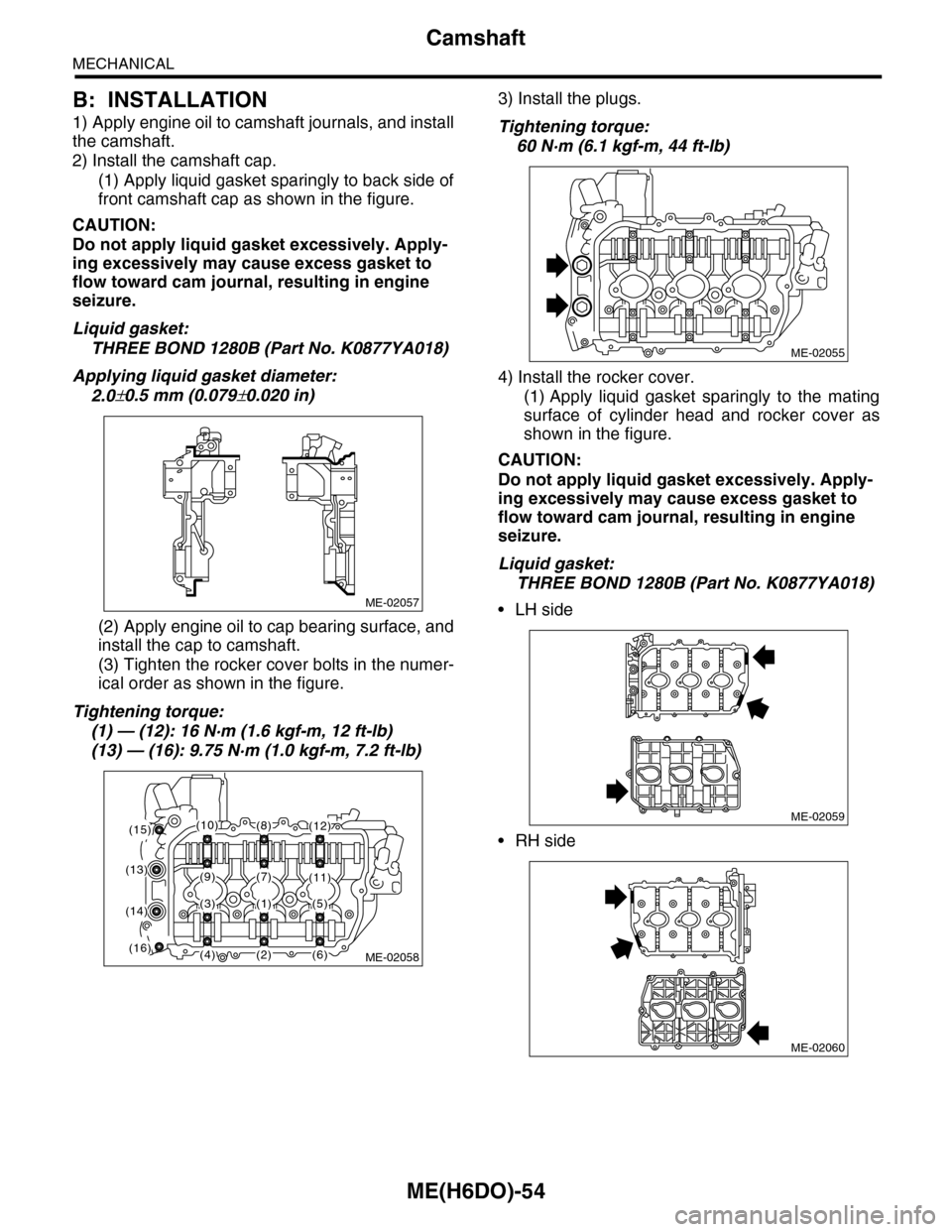
(1) Apply liquid gasket sparingly to back side of
front camshaft cap as shown in the figure.
CAUTION:
Do not apply liquid gasket excessively. Apply-
ing excessively may cause excess gasket to
flow toward cam journal, resulting in engine
seizure.
Liquid gasket:
THREE BOND 1280B (Part No. K0877YA018)
Applying liquid gasket diameter:
2.0±0.5 mm (0.079±0.020 in)
(2) Apply engine oil to cap bearing surface, and
install the cap to camshaft.
(3) Tighten the rocker cover bolts in the numer-
ical order as shown in the figure.
Tightening torque:
(1) — (12): 16 N·m (1.6 kgf-m, 12 ft-lb)
(13) — (16): 9.75 N·m (1.0 kgf-m, 7.2 ft-lb)
3) Install the plugs.
Tightening torque:
60 N·m (6.1 kgf-m, 44 ft-lb)
4) Install the rocker cover.
(1) Apply liquid gasket sparingly to the mating
surface of cylinder head and rocker cover as
shown in the figure.
CAUTION:
Do not apply liquid gasket excessively. Apply-
ing excessively may cause excess gasket to
flow toward cam journal, resulting in engine
seizure.
Liquid gasket:
THREE BOND 1280B (Part No. K0877YA018)
•LH side
•RH side
ME-02057
ME-02058
(1)
(2)
(8)
(7)(9)
(3)
(4)
(5)
(6)
(10)
(11)(13)
(14)
(15)
(16)
(12)
ME-02055
ME-02059
ME-02060
Page 1921 of 2453
ME(H6DO)-55
Camshaft
MECHANICAL
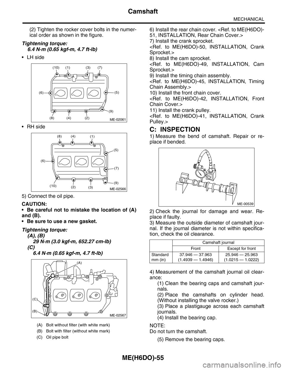
(2) Tighten the rocker cover bolts in the numer-
ical order as shown in the figure.
Tightening torque:
6.4 N·m (0.65 kgf-m, 4.7 ft-lb)
•LH side
•RH side
5) Connect the oil pipe.
CAUTION:
•Be careful not to mistake the location of (A)
and (B).
•Be sure to use a new gasket.
Tightening torque:
(A), (B)
29 N·m (3.0 kgf-m, 652.27 cm-lb)
(C)
6.4 N·m (0.65 kgf-m, 4.7 ft-lb)
6) Install the rear chain cover.
51, INSTALLATION, Rear Chain Cover.>
7) Install the crank sprocket.
Sprocket.>
8) Install the cam sprocket.
Sprocket.>
9) Install the timing chain assembly.
Chain Assembly.>
10) Install the front chain cover.
Chain Cover.>
11) Install the crank pulley.
Pulley.>
C: INSPECTION
1) Measure the bend of camshaft. Repair or re-
place if bended.
2) Check the journal for damage and wear. Re-
place if faulty.
3) Measure the outside diameter of camshaft jour-
nal. If the journal diameter is not within specifica-
tion, check the oil clearance.
4) Measurement of the camshaft journal oil clear-
ance:
(1) Clean the bearing caps and camshaft jour-
nals.
(2) Place the camshafts on cylinder head.
(Without installing the valve rocker.)
(3) Place a plastigauge across each camshaft
journals.
(4) Install the bearing cap.
NOTE:
Do not turn the camshaft.
(5) Remove the bearing caps.
(A) Bolt without filter (with white mark)
(B) Bolt with filter (without white mark)
(C) Oil pipe bolt
ME-02061(2)
(7)(3)(1)(10)
(6)
(8)(4)
(5)
(9)
ME-02566
(8)(4)(1)
(5)
(7)
(9)(3)(2)
(6)
(10)
ME-02567
(A)
(C)
(B)
Camshaft journal
Front Except for front
Standard
mm (in)
37.946 — 37.963
(1.4939 — 1.4946)
25.946 — 25.963
(1.0215 — 1.0222)
ME-00539