Page 1955 of 2453
ME(H6DO)-89
Engine Trouble in General
MECHANICAL
10. Excessive fuel consump-
tion
Engine control system A
Intake system Dirty air cleaner element A
Chain Defective timing B
Compression Incorrect valve clearance B
Loosened spark plug or defective gasket C
Loosened cylinder head bolt or defective gasket C
Improper valve sealing B
Defective valve stem C
Wor n or broken valve spr ing C
Wor n or stuck piston r ings, cylinder and piston B
Incorrect valve timing B
Tr o u b l e o f t a p p e t C
Tr o u b l e o f t a p p e t . I n c a s e n o i s e o c c u r s w i t h v a l v e m o v -
ing. Or the harness involved to oil switching solenoid
valve, variable valve lift diagnosis oil pressure switch
and variable valve lift has trouble in a past.
B
Lubrication system Incorrect oil pressure C
Cooling system Over-cooling C
Symptom Problem parts etc. Possible cause RANK
Page 1956 of 2453

ME(H6DO)-90
Engine Noise
MECHANICAL
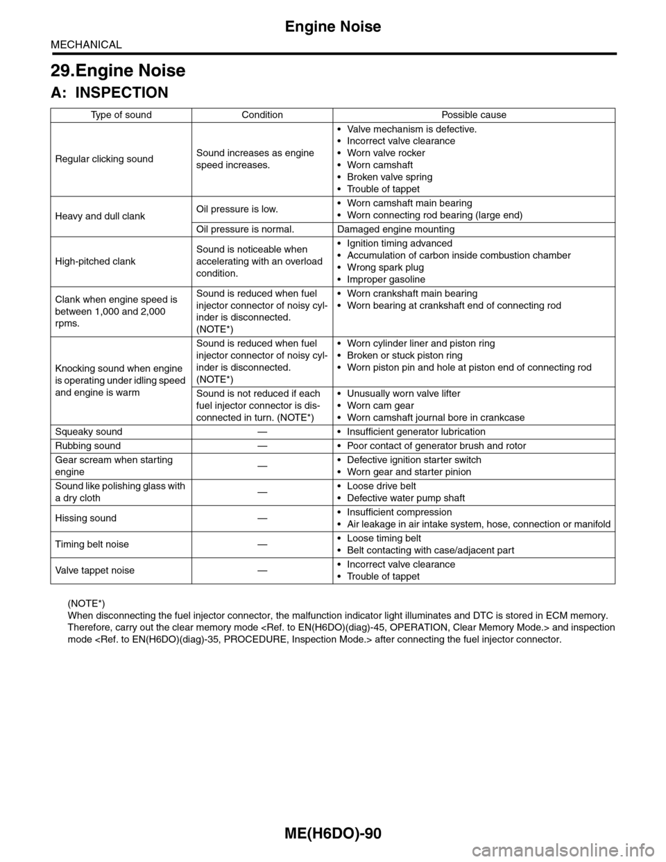
29.Engine Noise
A: INSPECTION
(NOTE*)
When disconnecting the fuel injector connector, the malfunction indicator light illuminates and DTC is stored in ECM memory.
Therefore, carry out the clear memory mode and inspection
mode after connecting the fuel injector connector.
Ty p e o f s o u n d C o n d i t i o n P o s s i b l e c a u s e
Regular clicking soundSound increases as engine
speed increases.
•Valve mechanism is defective.
•Incorrect valve clearance
•Worn valve rocker
•Worn camshaft
•Broken valve spring
•Trouble of tappet
Heavy and dull clankOil pressure is low.•Worn camshaft main bearing
•Worn connecting rod bearing (large end)
Oil pressure is normal. Damaged engine mounting
High-pitched clank
Sound is noticeable when
accelerating with an overload
condition.
•Ignition timing advanced
•Accumulation of carbon inside combustion chamber
•Wrong spark plug
•Improper gasoline
Clank when engine speed is
between 1,000 and 2,000
rpms.
Sound is reduced when fuel
injector connector of noisy cyl-
inder is disconnected.
(NOTE*)
•Worn crankshaft main bearing
•Worn bearing at crankshaft end of connecting rod
Knocking sound when engine
is operating under idling speed
and engine is warm
Sound is reduced when fuel
injector connector of noisy cyl-
inder is disconnected.
(NOTE*)
•Worn cylinder liner and piston ring
•Broken or stuck piston ring
•Worn piston pin and hole at piston end of connecting rod
Sound is not reduced if each
fuel injector connector is dis-
connected in turn. (NOTE*)
•Unusually worn valve lifter
•Worn cam gear
•Worn camshaft journal bore in crankcase
Squeaky sound — • Insufficient generator lubrication
Rubbing sound — • Poor contact of generator brush and rotor
Gear scream when starting
engine—•Defective ignition starter switch
•Worn gear and starter pinion
Sound like polishing glass with
a dry cloth—•Loose drive belt
•Defective water pump shaft
Hissing sound —•Insufficient compression
•Air leakage in air intake system, hose, connection or manifold
Timing belt noise —•Loose timing belt
•Belt contacting with case/adjacent part
Va l ve t a p p e t n o i s e —•Incorrect valve clearance
•Trouble of tappet
Page 1992 of 2453
PM-9
Spark Plug
PERIODIC MAINTENANCE SERVICES
5. Spark Plug
A: REPLACEMENT
1) Remove the battery and battery carrier.
2) Remove the air cleaner case.
3) Detach the connector from ignition coil.
4) Remove the ignition coil.
5) Remove the spark plug with a spark plug socket.
6) Tighten the new spark plug lightly with hand, and
then secure with a spark plug socket to the speci-
fied torque.
Recommended spark plug:
NGK: ILFR6B
Tightening torque:
21 N·m (2.1 kgf-m, 15.2 ft-lb)
7) Tighten the ignition coil.
Tightening torque:
16 N·m (1.6 kgf-m, 11.7 ft-lb)
NOTE:
•Be sure to place the gasket between the cylinder
head and spark plug.
•If the torque wrench is not available, tighten the
spark plug until gasket contacts cylinder head; then
tighten further 1/4 to 1/2 turns.
(A) Bracket
(B) Connector
IG-02004(B)
(A)
PM-00112
Page 2002 of 2453

PM-19
Brake Line
PERIODIC MAINTENANCE SERVICES
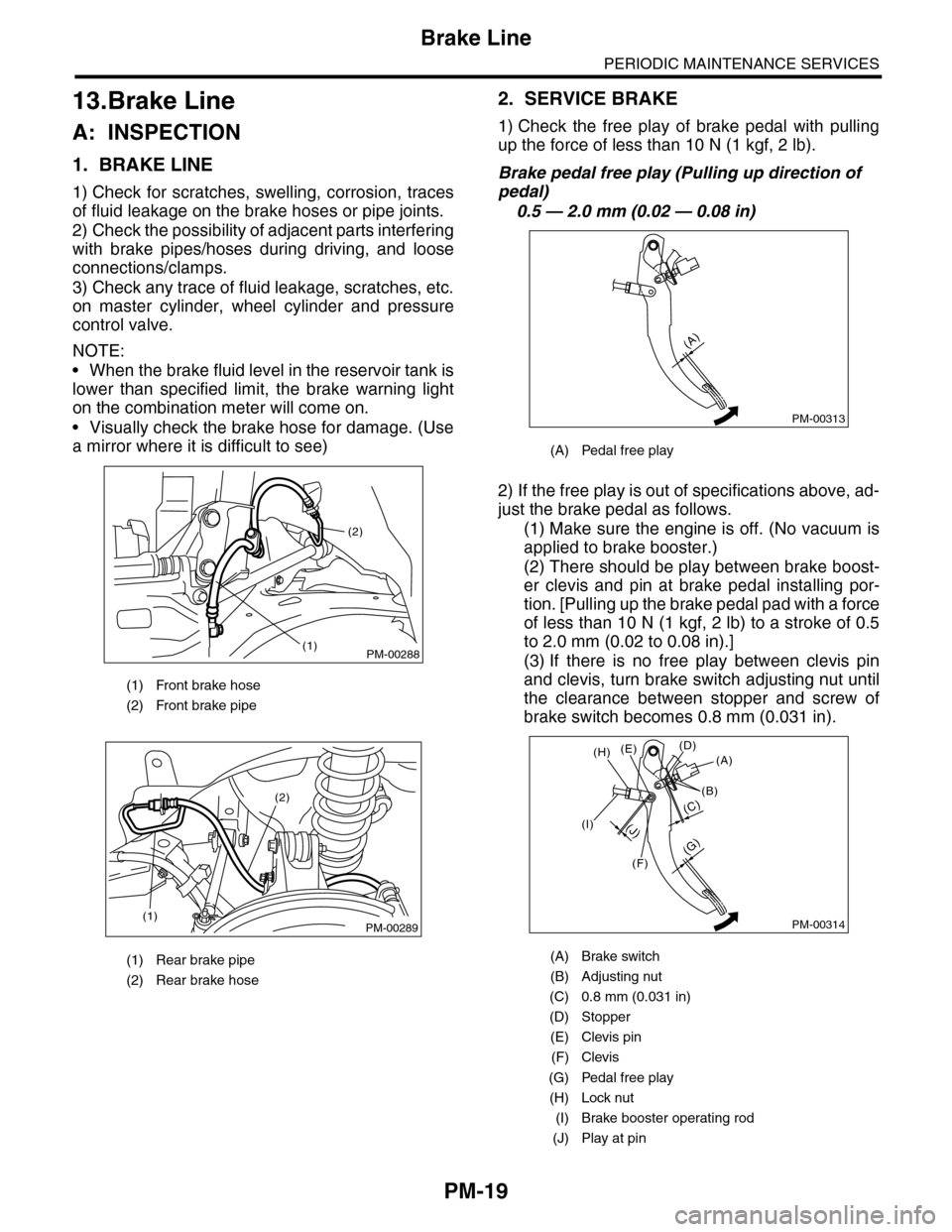
13.Brake Line
A: INSPECTION
1. BRAKE LINE
1) Check for scratches, swelling, corrosion, traces
of fluid leakage on the brake hoses or pipe joints.
2) Check the possibility of adjacent parts interfering
with brake pipes/hoses during driving, and loose
connections/clamps.
3) Check any trace of fluid leakage, scratches, etc.
on master cylinder, wheel cylinder and pressure
control valve.
NOTE:
•When the brake fluid level in the reservoir tank is
lower than specified limit, the brake warning light
on the combination meter will come on.
•Visually check the brake hose for damage. (Use
a mirror where it is difficult to see)
2. SERVICE BRAKE
1) Check the free play of brake pedal with pulling
up the force of less than 10 N (1 kgf, 2 lb).
Brake pedal free play (Pulling up direction of
pedal)
0.5 — 2.0 mm (0.02 — 0.08 in)
2) If the free play is out of specifications above, ad-
just the brake pedal as follows.
(1) Make sure the engine is off. (No vacuum is
applied to brake booster.)
(2) There should be play between brake boost-
er clevis and pin at brake pedal installing por-
tion. [Pulling up the brake pedal pad with a force
of less than 10 N (1 kgf, 2 lb) to a stroke of 0.5
to 2.0 mm (0.02 to 0.08 in).]
(3) If there is no free play between clevis pin
and clevis, turn brake switch adjusting nut until
the clearance between stopper and screw of
brake switch becomes 0.8 mm (0.031 in).
(1) Front brake hose
(2) Front brake pipe
(1) Rear brake pipe
(2) Rear brake hose
PM-00288
(2)
(1)
PM-00289(1)
(2)
(A) Pedal free play
(A) Brake switch
(B) Adjusting nut
(C) 0.8 mm (0.031 in)
(D) Stopper
(E) Clevis pin
(F) Clevis
(G) Pedal free play
(H) Lock nut
(I) Brake booster operating rod
(J) Play at pin
PM-00313
(A)
PM-00314
(G)
(A)(D)(E)
(B)
(C)
(F)
(J)(I)
(H)
Page 2004 of 2453

PM-21
Brake Fluid
PERIODIC MAINTENANCE SERVICES
14.Brake Fluid
A: REPLACEMENT
1) Either jack-up the vehicle and place a rigid rack
under it, or lift-up the vehicle.
2) Remove all the wheels.
3) Drain the brake fluid from master cylinder.
4) Refill the reservoir tank with recommended
brake fluid.
Recommended brake fluid:
Refer to “RM” section.
RECOMMENDED MATERIALS, Recommend-
ed Materials.>
NOTE:
•Avoid mixing different brands of brake fluid to
prevent degrading the quality of fluid.
•Be careful not to allow dirt or dust to get into the
reservoir tank.
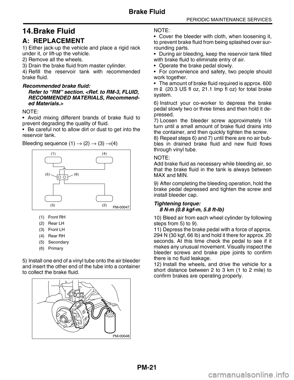
Bleeding sequence (1) → (2) → (3) →(4)
5) Install one end of a vinyl tube onto the air bleeder
and insert the other end of the tube into a container
to collect the brake fluid.
NOTE:
•Cover the bleeder with cloth, when loosening it,
to prevent brake fluid from being splashed over sur-
rounding parts.
•During air bleeding, keep the reservoir tank filled
with brake fluid to eliminate entry of air.
•Operate the brake pedal slowly.
•For convenience and safety, two people should
work together.
•The amount of brake fluid required is approx. 600
m2 (20.3 US fl oz, 21.1 Imp fl oz) for total brake
system.
6) Instruct your co-worker to depress the brake
pedal slowly two or three times and then hold it de-
pressed.
7) Loosen the bleeder screw approximately 1/4
turn until a small amount of brake fluid drains into
the container, and then quickly tighten the screw.
8) Repeat steps 6) and 7) until there are no air bub-
bles in drained brake fluid and new fluid flows
through vinyl tube.
NOTE:
Add brake fluid as necessary while bleeding air, so
that the brake fluid in the tank is always between
MAX and MIN.
9) After completing the bleeding operation, hold the
brake pedal depressed and tighten the screw and
install bleeder cap.
Tightening torque:
8 N·m (0.8 kgf-m, 5.8 ft-lb)
10) Bleed air from each wheel cylinder by following
steps from 5) to 9).
11) Depress the brake pedal with a force of approx.
294 N (30 kgf, 66 lb) and hold it there for approx. 20
seconds. At this time check the pedal to see if it
makes any unusual movement. Visually inspect the
bleeder screws and brake pipe joints to confirm
there is no fluid leakage.
12) Install the wheels, and drive the vehicle for a
short distance between 2 to 3 km (1 to 2 mile) to
confirm brakes are operating properly.
(1) Front RH
(2) Rear LH
(3) Front LH
(4) Rear RH
(5) Secondary
(6) Primary
(1) (4)
(2)(3)
(5) (6)
PM-00047
PM-00048
Page 2257 of 2453
CS-5
AT Shift Lock Control System
CONTROL SYSTEMS
2. AT Shift Lock Control System
A: LOCATION
(1) TCM (“P” range) (4) Key cylinder (with built-in key
warning switch)
(6) “P” range switch
(2) Body integrated unit (7) Key lock solenoid
(3) Stop light switch (5) Shift lock solenoid ASSY
CS-00595
(4)
(6)
(5)
(7)(1)
(2)
(3)