2009 SUBARU TRIBECA cylinder
[x] Cancel search: cylinderPage 741 of 2453

BR-27
Brake Booster
BRAKE
B: INSTALLATION
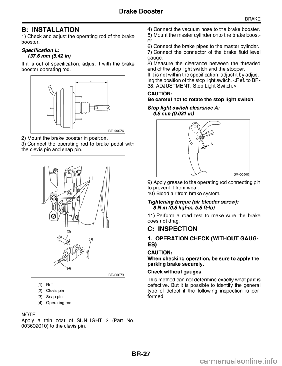
1) Check and adjust the operating rod of the brake
booster.
Specification L:
137.6 mm (5.42 in)
If it is out of specification, adjust it with the brake
booster operating rod.
2) Mount the brake booster in position.
3) Connect the operating rod to brake pedal with
the clevis pin and snap pin.
NOTE:
Apply a thin coat of SUNLIGHT 2 (Part No.
003602010) to the clevis pin.
4) Connect the vacuum hose to the brake booster.
5) Mount the master cylinder onto the brake boost-
er.
6) Connect the brake pipes to the master cylinder.
7) Connect the connector of the brake fluid level
gauge.
8) Measure the clearance between the threaded
end of the stop light switch and the stopper.
If it is not within the specification, adjust it by adjust-
ing the position of the stop light switch.
CAUTION:
Be careful not to rotate the stop light switch.
Stop light switch clearance A:
0.8 mm (0.031 in)
9) Apply grease to the operating rod connecting pin
to prevent it from wear.
10) Bleed air from brake system.
Tightening torque (air bleeder screw):
8 N·m (0.8 kgf-m, 5.8 ft-lb)
11) Perform a road test to make sure the brake
does not drag.
C: INSPECTION
1. OPERATION CHECK (WITHOUT GAUG-
ES)
CAUTION:
When checking operation, be sure to apply the
parking brake securely.
Check without gauges
This method can not determine exactly what part is
defective. But it is possible to identify the general
type of defect if the following inspection is per-
formed.
(1) Nut
(2) Clevis pin
(3) Snap pin
(4) Operating rod
L
BR-00076
(1)
(3)
(4)
(2)
BR-00073
BR-00500
A
Page 744 of 2453

BR-30
Brake Fluid
BRAKE
10.Brake Fluid
A: INSPECTION
1) Check that the brake fluid level is between “MIN”
and “MAX”. If out of the specified range, refill or
drain fluid. If the fluid level is close to “MIN”, check
the brake pad for wear and refill the fluid.
2) Check the fluid for discoloration. If the fluid color
has changed excessively, drain the fluid and refill
with new fluid.
B: REPLACEMENT
CAUTION:
•Do not let brake fluid come into contact with
the painted surface of the vehicle body. Wash
away with water immediately and wipe off if it is
spilled by accident.
•Avoid mixing brake fluids of different brands
to prevent fluid performance from degrading.
•Be careful not to allow dirt or dust to enter the
reservoir tank.
NOTE:
•During the operation, keep the reservoir tank
filled with brake fluid to eliminate entry of air.
•Operate the brake pedal slowly.
•For convenience and safety, perform work with 2
people.
•The required amount of brake fluid is approxi-
mately 600 m2 (20 US fl oz, 21 Imp fl oz) for entire
brake system.
1) Lift-up the vehicle and set rigid racks at the spec-
ified locations, or keep the vehicle lifted.
2) Remove both the front and rear wheels.
3) Drain brake fluid from the reservoir tank.
4) Refill the reservoir tank with the recommended
brake fluid.
Recommended brake fluid:
Refer to the specification.
Perform the same procedure as for bleeding the
brake line, until new brake fluid comes out from vi-
nyl tube.
NOTE:
Perform the brake fluid replacement starting in or-
der from the farthest wheel cylinder from the mas-
ter cylinder.
Page 745 of 2453

BR-31
Air Bleeding
BRAKE
11.Air Bleeding
A: PROCEDURE
CAUTION:
•Do not let brake fluid come into contact with
the painted surface of the vehicle body. Wash
away with water immediately and wipe off if it is
spilled by accident.
•Avoid mixing brake fluids of different brands
to prevent fluid performance from degrading.
•Be careful not to allow dirt or dust to enter the
reservoir tank.
1. MASTER CYLINDER
NOTE:
•When the master cylinder is disassembled or the
reservoir tank is empty, bleed the master cylinder.
•If bleeding of the master cylinder is not neces-
sary, omit the following procedures, and perform
bleeding of the brake line.
1) Fill the reservoir tank of the master cylinder with
brake fluid.
NOTE:
While bleeding air, keep the reservoir tank filled
with brake fluid to prevent entry of air.
2) Disconnect the brake line at primary and sec-
ondary sides.
3) Wrap the master cylinder with a plastic bag.
4) Depress the brake pedal slowly and hold it.
5) Plug the outlet plug with your finger, and then re-
lease the brake pedal.
6) Repeat the step 4) and 5) several times.
7) Remove the plastic bag.
8) Install the brake pipe to the master cylinder.
Tightening torque:
19 N·m (1.9 kgf-m, 14.0 ft-lb)
9) Bleed air from the brake line.
2. BRAKE LINE
1) When the master cylinder is disassembled or the
reservoir tank is empty, bleed the master cylinder
before bleeding the brake line.
ing.>
2) Fill the reservoir tank of the master cylinder with
brake fluid.
NOTE:
While bleeding air, keep the reservoir tank filled
with brake fluid to prevent entry of air.
3) Attach one end of the vinyl tube to the air bleeder
and the other end to the brake fluid container.
4) Depress the brake pedal several times, and
keep it pressed.
5) Loosen the air bleeder screw to drain brake fluid.
Tighten the air bleeder quickly, and release the
brake pedal.
6) Repeat the steps 4) to 5) until there are no more
air bubbles in the vinyl tube.
7) Repeat the steps from 2) to 6) above to bleed air
from each wheel.
NOTE:
Perform the operation in the order from closest
wheel cylinder to the master cylinder.
8) Securely tighten the air bleeder screws.
Tightening torque:
8 N·m (0.8 kgf-m, 5.8 ft-lb)
9) Check that there are no brake fluid leaks in the
entire system.
BR-00090
BR-00091
BR-00087
Page 755 of 2453

BR-41
General Diagnostic Table
BRAKE
18.General Diagnostic Table
A: INSPECTION
Trouble and possible causeCorrective action
1. Insufficient braking
performance
(1) Fluid leakage from the hydraulic mechanism Correct or replace. (cup, piston seal, piston
boot, master cylinder piston kit, pipe or
hose)
(2) Entry of air into the hydraulic mechanism Bleed air.
(3) Wear, deteriorated surface material, water or fluid on
lining
Replace, grind or clean.
(4) Improper operation of master cylinder, disc caliper,
brake booster or check valve
Correct or replace.
2. Unstable or uneven
braking
(1) Fluid on lining or rotor Correct the cause of fluid leakage, and
clean or replace.
(2) Rotor defective Repair or replace the rotor.
(3) Improper lining contact, deteriorated surface, deterio-
rated or wear lining material
Repair by grinding, or replace.
(4) Deformed back plate Repair or replace.
(5) Over inflation of tires Adjust air pressure.
(6) Defective wheel alignment Adjust alignment.
(7) Loose back plate or suppor t installation bolt Tighten to the specified torque.
(8) Faulty wheel bearing Replace.
(9) Defective hydraulic system Replace the cylinder, brake pipe or hose.
(10) Unstable effect of parking brake Check, adjust or replace the rear brake and
cable system.
3. Excessive pedal
stroke
(1) Entry of air into the hydraulic mechanism Bleed air.
(2) Excessive play in the master cylinder push rod Adjust.
(3) Fluid leakage from the hydraulic mechanism Correct or replace. (cup, piston seal, piston
boot, master cylinder piston kit, pipe or
hose)
(4) Improper lining contact or worn lining Correct or replace.
4. Brake dragging or
improper brake
return
(1) Insufficient pedal play Adjust play.
(2) Improper master cylinder return Clean or replace the cylinder.
(3) Clogged hydraulic system Replace.
(4) Improper return or adjustment of parking brake Repair or adjust.
(5) Weakened spring tension or breakage of shoe return
spring
Replace the spring.
(6) Improper disc caliper operation Correct or replace.
(7) Faulty wheel bearing Replace.
Brake noise (1)
(creaking sound)
(1) Hardened or deteriorated brake pad Replace the pad.
(2) Worn brake pad Replace the pad.
(3) Loose back plate or suppor t installation bolt Tighten to the specified torque.
(4) Loose wheel bearing Tighten to the specified torque.
(5) Dir ty rotor Clean the rotor, or clean and replace brake
assembly.
6. Brake noise (2)
(hissing sound)
(1) Worn brake pad Replace the pad.
(2) Improperly installed pad Correct or replace the pad.
(3) Loose or bent rotor Retighten or replace.
7. Brake noise (3)
(click sound)
Excessively worn pad or suppor t Replace the pad or the suppor t.
Page 785 of 2453

BVC(diag)-30
General Diagnostic Table
BRAKE VACUUM CONTROL (BVC) (DIAGNOSTICS)
12.General Diagnostic Table
A: INSPECTION
Symptom Main probable cause Other probable cause
Po or b rake pe r -
for mance
Long braking/
stopping dis-
tance
•Brake pad
•Aeration to brake line
•Tire specifications, tire wear and air
pressures
•Incorrect wiring or piping connections
•Master cylinder
•Brake caliper
•Disc rotor
•Brake pipe
•Brake booster
Long brake
pedal stroke
•Aeration to brake line
•Brake pedal play
•Master cylinder
•Brake caliper
•Brake pad
•Brake pipe
•Brake booster
Short brake
pedal stroke
•Brake vacuum pump
•Brake vacuum sensor
•Brake vacuum hose
•Master cylinder
•Brake caliper
•Brake pad
•Brake pipe
•Brake booster
Page 866 of 2453

FS-18
Front Arm
FRONT SUSPENSION
2. REAR BUSHING
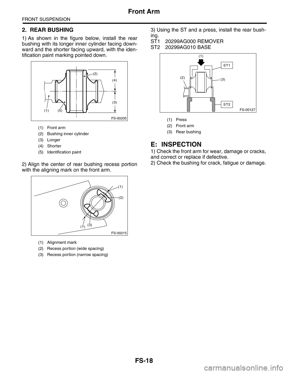
1) As shown in the figure below, install the rear
bushing with its longer inner cylinder facing down-
ward and the shorter facing upward, with the iden-
tification paint marking pointed down.
2) Align the center of rear bushing recess portion
with the aligning mark on the front arm.
3) Using the ST and a press, install the rear bush-
ing.
ST1 20299AG000 REMOVER
ST2 20299AG010 BASE
E: INSPECTION
1) Check the front arm for wear, damage or cracks,
and correct or replace if defective.
2) Check the bushing for crack, fatigue or damage.
(1) Front arm
(2) Bushing inner cylinder
(3) Longer
(4) Shorter
(5) Identification paint
(1) Alignment mark
(2) Recess portion (wide spacing)
(3) Recess portion (narrow spacing)
FS-00205
(4)
(3)
(2)
(5)(1)
FS-00215
(2)
(1)
(1)(3)
(1) Press
(2) Front arm
(3) Rear bushing
FS-00127
(1)
(2)(3)
ST2
ST1
Page 891 of 2453

PS-11
General Description
POWER ASSISTED SYSTEM (POWER STEERING)
34199AG090 INSTALLER &
REMOVER
•Used for installing oil seal of valve housing.
•Used for installing ball bearing of valve hous-
ing.
•Used for removing oil seal and ball bearing
from valve housing.
34199XA020 FORMER PISTON
44
•Used for forming seal ring of rack.
•Used with Guide G (26)(34199AG060).
34199XA000 INSTALLER 44 Used for pressing-fit oil seal of gearbox cylinder.
34199AE020 MOUNT Used to remove the oil pump.
34199AE030 INSTALLER Used for installing the oil seal to the oil pump.
ILLUSTRATION TOOL NUMBER DESCRIPTION REMARKS
ST34199AG090
ST34199XA020
ST34199XA000
ST34199AE020
ST34199AE030
Page 905 of 2453

PS-25
Steering Gearbox
POWER ASSISTED SYSTEM (POWER STEERING)
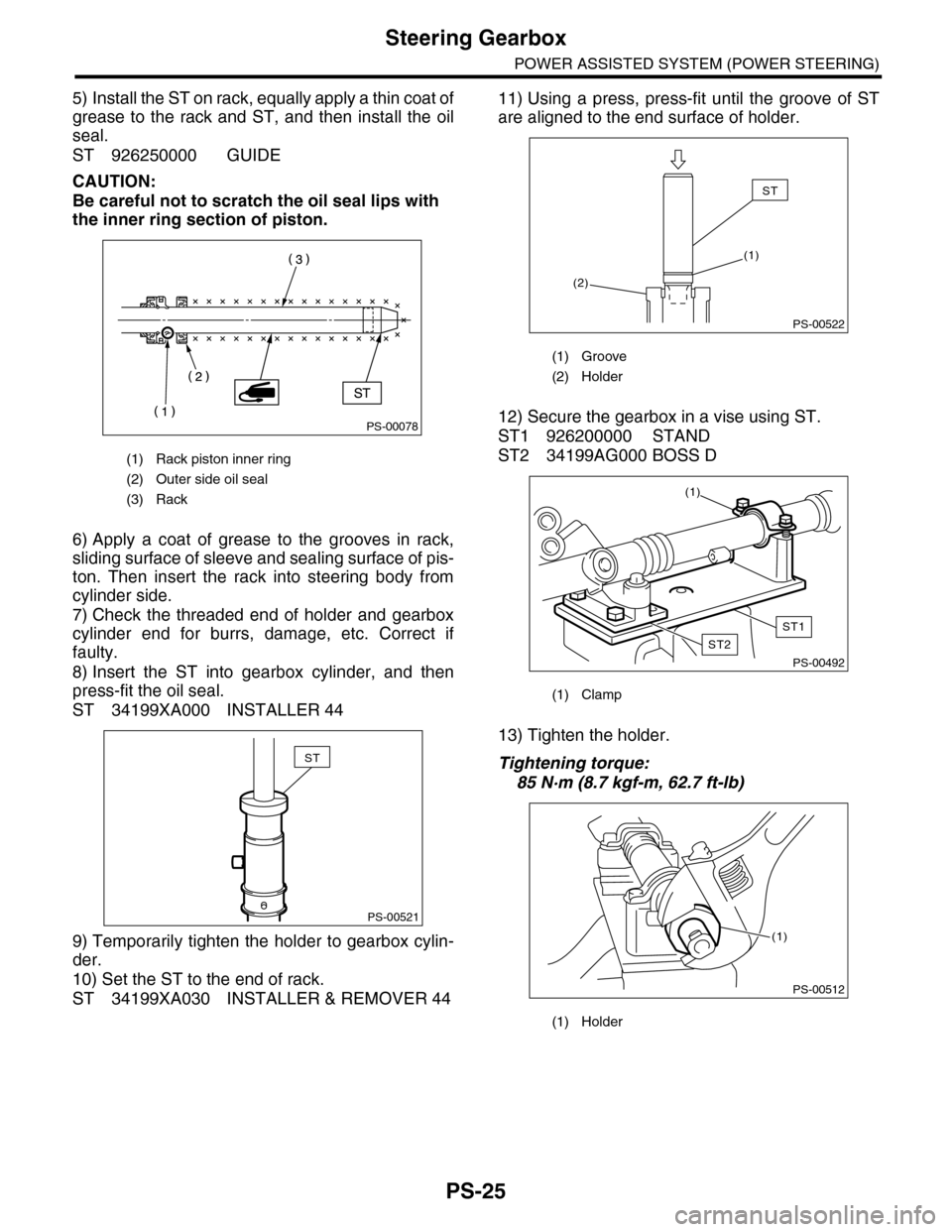
5) Install the ST on rack, equally apply a thin coat of
grease to the rack and ST, and then install the oil
seal.
ST 926250000 GUIDE
CAUTION:
Be careful not to scratch the oil seal lips with
the inner ring section of piston.
6) Apply a coat of grease to the grooves in rack,
sliding surface of sleeve and sealing surface of pis-
ton. Then insert the rack into steering body from
cylinder side.
7) Check the threaded end of holder and gearbox
cylinder end for burrs, damage, etc. Correct if
faulty.
8) Insert the ST into gearbox cylinder, and then
press-fit the oil seal.
ST 34199XA000 INSTALLER 44
9) Temporarily tighten the holder to gearbox cylin-
der.
10) Set the ST to the end of rack.
ST 34199XA030 INSTALLER & REMOVER 44
11) Using a press, press-fit until the groove of ST
are aligned to the end surface of holder.
12) Secure the gearbox in a vise using ST.
ST1 926200000 STAND
ST2 34199AG000 BOSS D
13) Tighten the holder.
Tightening torque:
85 N·m (8.7 kgf-m, 62.7 ft-lb)
(1) Rack piston inner ring
(2) Outer side oil seal
(3) Rack
PS-00078
PS-00521
ST
(1) Groove
(2) Holder
(1) Clamp
(1) Holder
PS-00522
ST
(1)
(2)
PS-00492
(1)
ST1
ST2
PS-00512
(1)