Page 558 of 2453
LI-25
Back-up Light Bulb
LIGHTING SYSTEM
23.Back-up Light Bulb
A: REMOVAL
1) Remove the bulb inspection cover of the rear
gate trim.
2) Turn the socket and remove the bulb.
B: INSTALLATION
Install in the reverse order of removal.
C: INSPECTION
1) Visually check the bulb for blow out.
2) Check the bulb specification.
SPECIFICATION, General Description.>
3) If NG, replace the bulb with a new one.
Page 586 of 2453

OD(diag)-18
Subaru Select Monitor
OCCUPANT DETECTION SYSTEM (DIAGNOSTICS)
3. CLEAR MEMORY MODE
Clear the DTC stored in the airbag control module
after repairing the airbag system and occupant de-
tection system. (After the breakdown is recovered,
the breakdown code for completed recoveries are
read out when the next breakdown occurs if the
memory clear work is not performed.)
1) On the «Main Menu» display screen, select the
{Each System Check} and press the [YES] key.
2) On the «System Selection Menu» display
screen, select the {Airbag System} and press the
[YES] key.
3) On the {Airbag System} menu screen, select the
{Clear Memory} and press the [YES] key.
4) When the “Clear Memory?” is shown on the
screen, press the [YES] key.
5) When “Done” is displayed, turn the Subaru Se-
lect Monitor to OFF.
NOTE:
For details concerning operation procedure, refer
to the “SUBARU SELECT MONITOR OPERATION
MANUAL”.
4. SYSTEM CALIBRATION (REZEROING)
NOTE:
When replacing the occupant detection system, or
removing and disassembling the passenger’s seat,
always perform the system calibration after install-
ing a seat in the vehicle.
CAUTION:
When the trouble occurs in the system during
calibration process, “Occupant detection cali-
bration failure” is detected in the DTC 2A of the
airbag system and the airbag warning light
lights. In this case, after turning the ignition
switch to OFF once, redo the system calibration
(Rezeroing), or after clearing the cause of the
failure, perform the system calibration again.
1) Park empty vehicle on a level surface.
2) On the «Main Menu» display screen, select the
{Each System Check} and press the [YES] key.
3) On the «System Selection Menu» display
screen, select the {Occupant Detection System}
and press the [YES] key.
4) On the Occupant Detection System display
screen, select the {Zero Point Adjustment} and
press the [YES] key.
5) “See service manual. And check vehicle condi-
tion for successfully completing the rezeroing.” is
displayed. Check the following to adjust the condi-
tion of the vehicle.
•Adjust the seat backrest to be vertical. (Press the
power seat switch to put the seat in a position
where it will not move.)
•Adjust the seat sliding position to all the way
back. (Press the power seat switch to put the seat
in a position where it will not move.)
•Do not place anything on the top of the seat
cushion.
•Sit on the seat cushion to smooth the seat sur-
face.
•Check that the passenger’s seat belt is not in-
serted into the buckle, not tense or not stuck.
•Check that ambient temperature is in a range
from 0 to 40°C.
6) When the «Re-zeroing Adjust the passenger
seat to the condition shown in service manual» is
displayed, slide the passenger seat all the way to
the back, check that the backrest is adjusted to all
the way up, and press the [YES] key.
7) When the «Re-zeroing Unbelt the Passenger
seatbelt Continue: YES, Quit: NO» is displayed,
make sure the passenger’s seatbelt is disconnect-
ed from the buckle and press the [YES] key.
8) When the «Re-zeroing Empty the passenger
seat Continue: YES, Quit: NO» is displayed, make
sure that the passenger’s seat is empty, air bag
OFF indicator illuminates and air bag ON indicator
does not illuminate, and press the [YES] key.
NOTE:
•After pressing the [YES] key, «Now processing
.... Wait for a while. Do not touch or give impact to
vehicle and seat» is displayed. Do not touch or rock
the vehicle while the message is displayed.
•During the system calibration process, if the
«Re-zeroing is unsuccessful See service manual
Press YES to END» is displayed, go to step 10).
9) When the re-zeroing is ended normally, the«Re-
zeroing is successfully completed Press YES to
END» is displayed. Press the [YES] key and turn
the ignition switch to OFF to finish the diagnosis.
OD-00025
Page 602 of 2453

SB-5
General Description
SEAT BELT SYSTEM
B: CAUTION
•Before starting the work, turn the ignition switch
to OFF, disconnect the battery ground cable and
wait for 20 seconds or more.
•The pretensioner system has a backup power
source. The pretensioner might deploy if you do not
wait for 20 seconds or more before starting work.
•Do not drop or apply any impact to the preten-
sioner.
•If oil, grease or water gets on the pretensioner,
wipe it off immediately with a dry cloth.
•Do not expose the pretensioner to high tempera-
ture or flame.
•Do not allow current to flow through or voltage to
reach the pretensioner. Do not use a circuit tester
to check resistance of the pretensioner.
•Do not disassemble or attempt to repair the pre-
tensioner. If it is dented, cracked or deformed, re-
place it with a new one.
•Do not use the airbag or pretensioner parts from
other vehicles. Always replace parts with new
parts.
•When handling a seat belt with deployed preten-
sioner, wear gloves and goggles. Wash your hands
afterwards.
•Do not reuse a seat belt with deployed preten-
sioner.
•If material from the airbag enters the eyes or con-
tacts skin during deployment, wash it away with
clean water, and then consult a doctor.
C: PREPARATION TOOL
1. GENERAL TOOL
TOOL NAME REMARKS
TO RX® T50Used for removing and installing the inner seat belt assembly.
Page 607 of 2453

SB-10
Front Seat Belt
SEAT BELT SYSTEM
5. Front Seat Belt
A: REMOVAL
1. OUTER SEAT BELT ASSEMBLY
1) Fold the backrest all the way forward, and then
move the front seat all the way forward.
2) Turn the ignition switch to OFF, disconnect the
battery ground cable, and wait more than 20 sec-
onds.
3) Remove the center pillar lower trim and center
pillar upper trim.
LOWER TRIM, REMOVAL, Side Trim.>
EI-44, CENTER PILLAR UPPER TRIM, REMOV-
AL, Side Trim.>
4) Remove the bolt, and then remove the shoulder
anchor.
5) Remove the bolt, and then remove the adjust-
able anchor assembly.
6) Disconnect connector (A) of the pretensioner,
and remove the lower anchor bolt and seat belt re-
tractor.
7) On the passenger side, disconnect connector of
the belt tension sensor.
CAUTION:
•Do not drop or subject the pretensioner to
any impact.
•Since the pretensioner and bracket are inte-
grated as a unit, do not disassemble them.
2. INNER SEAT BELT ASSEMBLY
1) Turn the ignition switch to OFF, disconnect the
battery ground cable, and wait more than 20 sec-
onds.
2) Remove the four bolts in the slide rail LH and
RH.
3) Disconnect the seat belt warning light connector
under the seat.
4) Remove the harness clips from the back of the
seat.
5) Remove the TORX® bolt, and then remove the
inner seat belt assembly.
SB-00152
SB-00153
SB-00306
(A)
SB-00319
SB-00307
Page 609 of 2453

SB-12
Second Seat Belt
SEAT BELT SYSTEM
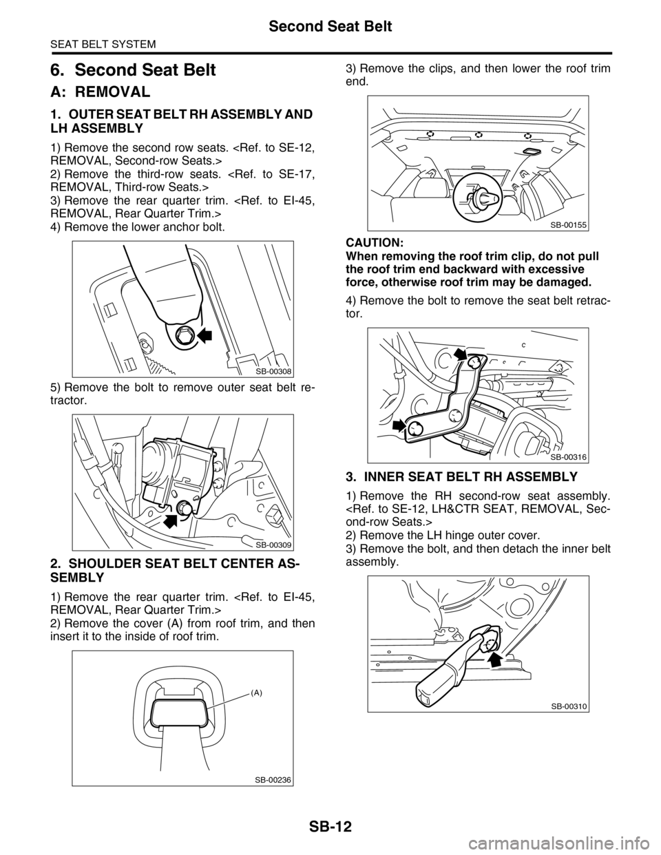
6. Second Seat Belt
A: REMOVAL
1. OUTER SEAT BELT RH ASSEMBLY AND
LH ASSEMBLY
1) Remove the second row seats.
REMOVAL, Second-row Seats.>
2) Remove the third-row seats.
REMOVAL, Third-row Seats.>
3) Remove the rear quarter trim.
REMOVAL, Rear Quarter Trim.>
4) Remove the lower anchor bolt.
5) Remove the bolt to remove outer seat belt re-
tractor.
2. SHOULDER SEAT BELT CENTER AS-
SEMBLY
1) Remove the rear quarter trim.
REMOVAL, Rear Quarter Trim.>
2) Remove the cover (A) from roof trim, and then
insert it to the inside of roof trim.
3) Remove the clips, and then lower the roof trim
end.
CAUTION:
When removing the roof trim clip, do not pull
the roof trim end backward with excessive
force, otherwise roof trim may be damaged.
4) Remove the bolt to remove the seat belt retrac-
tor.
3. INNER SEAT BELT RH ASSEMBLY
1) Remove the RH second-row seat assembly.
ond-row Seats.>
2) Remove the LH hinge outer cover.
3) Remove the bolt, and then detach the inner belt
assembly.
SB-00308
SB-00309
SB-00236
(A)
SB-00155
SB-00316
SB-00310
Page 610 of 2453
SB-13
Second Seat Belt
SEAT BELT SYSTEM
4. SHOULDER SEAT BELT CENTER
BUCKLE
1) Remove the LH second-row seat assembly.
ond-row Seats.>
2) Remove the RH hinge outer cover.
3) Remove the bolt, and then remove the shoulder
seat belt center buckle.
5. INNER SEAT BELT LH ASSEMBLY
1) Remove the LH second-row seat assembly.
ond-row Seats.>
2) Remove the bolt from the back of the seat cush-
ion, and then detach the inner belt assembly.
B: INSTALLATION
Install in the reverse order of removal.
CAUTION:
When installing, be careful of the routing of the
seatbelt, and make sure that the belt is not
twisted.
C: INSPECTION
Check for the following, and replace with new parts
if necessary.
•Seat belt is slackened, bent or worn. Seat belt is
abnormally wound or extended.
•Inner belt is deformed or damaged.
•Seat belt buckle cannot be engaged properly.
SB-00311
SB-00312
Page 612 of 2453
SE-2
General Description
SEATS
1. General Description
A: COMPONENT
1. FRONT SEAT (DRIVER’S SEAT)
(1) Backrest cover (11) Rear leg cover inside (21) Power seat switch unit
(2) Backrest pad (12) Seat cushion cover (22) Seat heater unit
(3) Backrest frame ASSY (13) Seat cushion pad (23) Lumber support lever
(4) Headrest ASSY (14) Seat cushion frame ASSY (24) Slide rail cover
(5) Headrest lock bushing (15) Rear leg cover outside
(6) Side airbag module (16) Power seat switch knobTightening torque: N·m (kgf-m, ft-lb)
(7) Cover frame (17) Seat side cover outsideT1: 6 (0.61, 4.43)
(8) Backrest back cover (18) Hinge inner cover LHT2: 17.6 (1.79, 12.7)
(9) Seat side cover inside (19) Inner seat belt ASSYT3: 52 (5.30, 37.6)
(10) Hinge inner cover RH (20) Slide rail ASSYT4: 53 (5.40, 38.3)
(1)
(2)
(23)
(22)
(3)
(8)
(4)
(5)
(6)(9)
(10)(11)
(12)
(13)
(14)
(15)
(17)
(21)(19)
(18)
T4
T4
T2
T3
T1
T2
T3
(7)
(24)
(24)
T4
(16)
(20)
SE-00580
Page 613 of 2453
SE-3
General Description
SEATS
2. FRONT SEAT (DRIVER’S SEAT)
(1) Backrest cover (10) Hinge inner cover LH (19) Power seat switch unit
(2) Backrest pad (11) Rear leg cover inside (20) Inner seat belt ASSY
(3) Backrest frame ASSY (12) Seat cushion cover (21) Slide rail cover
(4) Headrest ASSY (13) Seat heater unit
(5) Headrest lock bushing (14) Seat cushion pad & frame ASSYTightening torque: N·m (kgf-m, ft-lb)
(6) Side airbag module (15) Rear leg cover outsideT1: 6 (0.61, 4.43)
(7) Cover frame (16) Hinge inner cover RHT2: 17.6 (1.79, 12.7)
(8) Backrest back cover (17) Seat side cover outsideT3: 52 (5.30, 37.6)
(9) Seat side cover inside (18) Power seat switch knobT4: 53 (5.40, 38.3)
T3
T3
(1)
(2)
(3)
(8)
(4)
(5)
(6)
(9)
(10)
(12)
T4
T2
T2
T1
T4
(7)
(11)
(15)
(14)
(21)
(20)
(16)
(13)
(19)
(18)
(17)
SE-00581