Page 492 of 2453
LAN(diag)-36
Diagnostic Procedure with Diagnostic Trouble Code (DTC)
LAN SYSTEM (DIAGNOSTICS)
D: DTC B0101 BATT P/SUPPLY MALFUNCTION CONT.
DTC DETECTING CONDITION:
Battery power supply control circuit is open or shorted.
TROUBLE SYMPTOM:
No malfunction occurs because the back-up power supply is activated.
NOTE:
When B0102 BATT p/supply (backup) malfunction is output at the same time, all the function of body inte-
grated unit may not operate.
WIRING DIAGRAM:
LAN00149
SYSTEM CONTROL POWER SUPPLYBACK-UP POWER
SUPPLY
BODY INTEGRATED UNIT
B7C2
A21C9B22C8
MICRO COMPUTER
C24B13
i84
B52
B280
R168C:B:
B:
A:
12345678910 11 12 19 2013 14 15 16 17 18
R168C:
B52B:
34128910 1112 13 14 15 16 17 18 19 20 21 22 23 24567
E
MAIN SBF-11BATTERY
B281C:
EE
B280B:
B281C:
567821943102422 2325111213141526 27281617181920 21
5467821931022 23111213141524 25 26 2716171828 29192021 30
i84A:
1234567891011121314151617181920212223242526272829303132333435
FB-18 NO.7MB-29 NO.8
Page 494 of 2453

LAN(diag)-38
Diagnostic Procedure with Diagnostic Trouble Code (DTC)
LAN SYSTEM (DIAGNOSTICS)
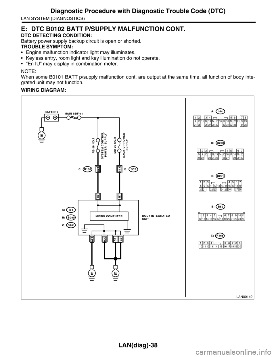
E: DTC B0102 BATT P/SUPPLY MALFUNCTION CONT.
DTC DETECTING CONDITION:
Battery power supply backup circuit is open or shorted.
TROUBLE SYMPTOM:
•Engine malfunction indicator light may illuminates.
•Keyless entry, room light and key illumination do not operate.
•“En IU” may display in combination meter.
NOTE:
When some B0101 BATT p/supply malfunction cont. are output at the same time, all function of body inte-
grated unit may not function.
WIRING DIAGRAM:
LAN00149
SYSTEM CONTROL POWER SUPPLYBACK-UP POWER
SUPPLY
BODY INTEGRATED UNIT
B7C2
A21C9B22C8
MICRO COMPUTER
C24B13
i84
B52
B280
R168C:B:
B:
A:
12345678910 11 12 19 2013 14 15 16 17 18
R168C:
B52B:
34128910 1112 13 14 15 16 17 18 19 20 21 22 23 24567
E
MAIN SBF-11BATTERY
B281C:
EE
B280B:
B281C:
567821943102422 2325111213141526 27281617181920 21
5467821931022 23111213141524 25 26 2716171828 29192021 30
i84A:
1234567891011121314151617181920212223242526272829303132333435
FB-18 NO.7MB-29 NO.8
Page 519 of 2453

LAN(diag)-63
Diagnostic Procedure with Diagnostic Trouble Code (DTC)
LAN SYSTEM (DIAGNOSTICS)
Q: DTC B0300 CAN-LS MALFUNCTION
DTC DETECTING CONDITION:
Either end of low-speed CAN communication line is open or shorted, the connector is not connected prop-
erly, or the terminal has poor caulking.
TROUBLE SYMPTOM:
“Er LC” is displayed in odo/trip meter, but communicating function is OK.
WIRING DIAGRAM:
LAN00192
TO POWER SUPPLY CIRCUITFB-10M/B FUSE NO.28 (P)
1
4
3
7
A9
A4
5
BODY INTEGRATED UNIT
ILLUMINATION & BACK-UPJOINT CONNECTOR
KEYLESS ENTRY CONTROL MODULE
i84
i99
i99
i96
E
i84i96i99
123456789101112131415161718192021222324252627282930313233343510 11 12349561728
12345678
Step Check Yes No
1CHECK HARNESS.
1) Disconnect the CAN junction connector
(i128) and body integrated unit connector (i84).
2) Measure the resistance between connector
terminals.
Connector & terminal
(i84) No. 26 — (i128) No. 7 to 12:
(i84) No. 27 — (i128) No. 1 to 6:
NOTE:The i128 junction connector is freely arranged.
Is the resistance less than 10
Ω?
Go to step 2.Repair the short
circuit of harness
or replace har-
ness.
Page 528 of 2453

LAN(diag)-72
Diagnostic Procedure with Diagnostic Trouble Code (DTC)
LAN SYSTEM (DIAGNOSTICS)
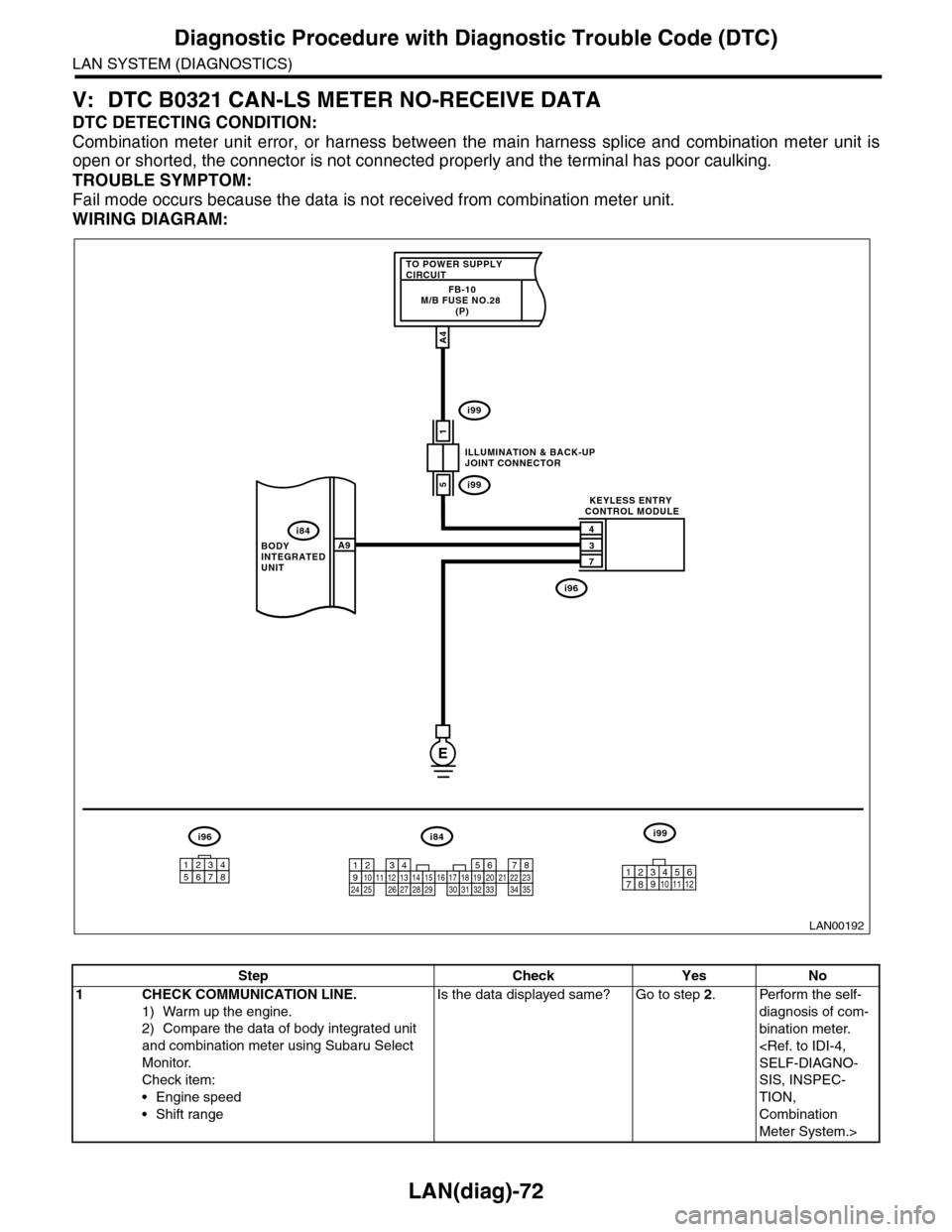
V: DTC B0321 CAN-LS METER NO-RECEIVE DATA
DTC DETECTING CONDITION:
Combination meter unit error, or harness between the main harness splice and combination meter unit is
open or shorted, the connector is not connected properly and the terminal has poor caulking.
TROUBLE SYMPTOM:
Fail mode occurs because the data is not received from combination meter unit.
WIRING DIAGRAM:
LAN00192
TO POWER SUPPLY CIRCUITFB-10M/B FUSE NO.28 (P)
1
4
3
7
A9
A4
5
BODY INTEGRATED UNIT
ILLUMINATION & BACK-UPJOINT CONNECTOR
KEYLESS ENTRY CONTROL MODULE
i84
i99
i99
i96
E
i84i96i99
123456789101112131415161718192021222324252627282930313233343510 11 12349561728
12345678
Step Check Yes No
1CHECK COMMUNICATION LINE.
1) Warm up the engine.
2) Compare the data of body integrated unit
and combination meter using Subaru Select
Monitor.
Check item:
•Engine speed
•Shift range
Is the data displayed same? Go to step 2.Perform the self-
diagnosis of com-
bination meter.
SELF-DIAGNO-
SIS, INSPEC-
TION,
Combination
Meter System.>
Page 535 of 2453

LI-2
General Description
LIGHTING SYSTEM
1. General Description
A: SPECIFICATION
B: CAUTION
•Before removing or installing parts, always disconnect the battery ground cable from battery. When replac-
ing the audio, control module and other parts provided with memory functions, record the memory contents
before disconnecting the battery ground cable. Otherwise, the memory is cleared.
•Reassemble the parts in the reverse order of disassembly procedure unless otherwise indicated.
•Adjust parts to the given specifications.
•Connect the connectors securely during reassembly.
•After reassembly, make sure functional parts operate smoothly.
WARNING:
•The air bag system wiring harness is routed near electrical parts and switches. Airbag system
wiring harnesses and connectors are yellow. Do not use electrical test equipment on these cir-
cuits.
•Be careful not to damage the air bag system wiring harness when servicing electrical parts and
switches.
C: PREPARATION TOOL
1. GENERAL TOOL
HeadlightHalogen type low beam 12 V — 55 W
Halogen type high beam 12 V — 65 W
Fr o nt t ur n si gn a l, p ar k in g 1 2 V — 27 / 8 W
Fr o nt si d e m ar ke r li gh t12 V — 5 W
Fr o nt fog li g ht12 V — 55 W
Side turn signal light 12 V — 2.7 W (LED)
Rear combination lightStop/Tail light/Rear side marker light 12 V — 21/5 W
Tu r n s i g n a l l i g h t 1 2 V — 2 1 W
Rear finisher light12 V — 3.8 W
Back-up light12 V — 16 W
License plate light12 V — 5 W
High-mounted stop light 12 V — 1.3 W (LED)
Room light12 V — 8 W
Spot map light12 V — 8 W
Luggage room light12 V — 13 W
Rear gate light12 V — 5 W
Glove box light12 V — 1.4 W
Door step light12 V — 3.5 W
TOOL NAME REMARKS
Circuit tester Used for measuring resistance and voltage.
Page 539 of 2453
LI-6
Back-up Light System
LIGHTING SYSTEM
5. Back-up Light System
A: WIRING DIAGRAM
1. BACK-UP LIGHT
System.>
B: INSPECTION
1. BACK-UP LIGHT RELAY
Measure the resistance between headlight relay
terminals when connecting terminal No. 4 to the
battery positive terminal and terminal No. 3 to the
battery ground terminal.
Current Terminal No. Standard
Ye s1 and 2Less than 1 Ω
No 1 MΩ or more
LI-00001
(1)(2)
(1)
(4)
(2)
(3)
(3)(4)
Page 546 of 2453

LI-13
Headlight Bulb
LIGHTING SYSTEM
11.Headlight Bulb
A: REMOVAL
1. HIGH BEAM AND LOW BEAM
CAUTION:
•Because the halogen bulb operates at a high
temperature, dirt and oil on the bulb surface re-
duces the bulb's service life. Hold the flange
portion when replacing the bulb. Never touch
the glass portion.
•Do not leave the headlight without a bulb for
a long time. Dust, moisture, etc. entering the
headlight may affect its performance.
1) Disconnect the ground cable from battery.
2) Remove the air intake duct. (When removing the
headlight bulb RH)
3) Remove the battery. (When removing the head-
light bulb LH)
4) Disconnect the harness connector.
5) Remove the bulb assembly (A) then remove the
high beam. To remove the low beam, remove the
back cover (B), and then go to the next step.
6) Remove the light bulb retaining spring (A) to re-
move bulb.
B: INSTALLATION
Install in the reverse order of removal.
C: INSPECTION
1) Visually check the bulb for blow out.
2) Check the bulb specification.
tion.>
3) If NG, replace the bulb with a new one.
IN-02134
LI-00506(B)
(A)
LI-00507
(A)
Page 551 of 2453
LI-18
Front Fog Light Bulb
LIGHTING SYSTEM
16.Front Fog Light Bulb
A: REMOVAL
1) Disconnect the ground cable from battery.
2) Disengage the three clips, and then turn over the
lower mud guard.
3) Disconnect the harness connector.
4) Remove the back cover.
5) Remove the spring retainer (A), then detach the
fog light bulb.
B: INSTALLATION
Install in the reverse order of removal.
C: INSPECTION
1) Visually check the bulb for blow out.
2) Check the bulb specification.
SPECIFICATION, General Description.>
3) If NG, replace the bulb with a new one.
LI-00510
LI-00511
(A)