Page 1834 of 2453

GD(H6DO)-222
Diagnostic Trouble Code (DTC) Detecting Criteria
GENERAL DESCRIPTION
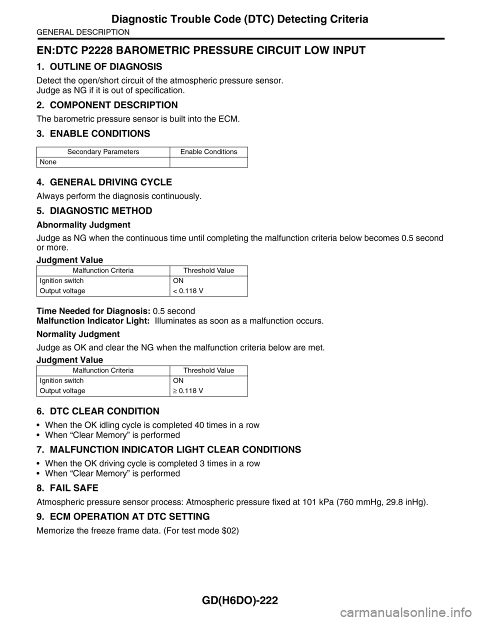
EN:DTC P2228 BAROMETRIC PRESSURE CIRCUIT LOW INPUT
1. OUTLINE OF DIAGNOSIS
Detect the open/short circuit of the atmospheric pressure sensor.
Judge as NG if it is out of specification.
2. COMPONENT DESCRIPTION
The barometric pressure sensor is built into the ECM.
3. ENABLE CONDITIONS
4. GENERAL DRIVING CYCLE
Always perform the diagnosis continuously.
5. DIAGNOSTIC METHOD
Abnormality Judgment
Judge as NG when the continuous time until completing the malfunction criteria below becomes 0.5 second
or more.
Time Needed for Diagnosis: 0.5 second
Malfunction Indicator Light: Illuminates as soon as a malfunction occurs.
Normality Judgment
Judge as OK and clear the NG when the malfunction criteria below are met.
6. DTC CLEAR CONDITION
•When the OK idling cycle is completed 40 times in a row
•When “Clear Memory” is performed
7. MALFUNCTION INDICATOR LIGHT CLEAR CONDITIONS
•When the OK driving cycle is completed 3 times in a row
•When “Clear Memory” is performed
8. FAIL SAFE
Atmospheric pressure sensor process: Atmospheric pressure fixed at 101 kPa (760 mmHg, 29.8 inHg).
9. ECM OPERATION AT DTC SETTING
Memorize the freeze frame data. (For test mode $02)
Secondary Parameters Enable Conditions
None
Judgment Value
Malfunction Criteria Threshold Value
Ignition switch ON
Output voltage < 0.118 V
Judgment Value
Malfunction Criteria Threshold Value
Ignition switch ON
Output voltage≥ 0.118 V
Page 1835 of 2453

GD(H6DO)-223
Diagnostic Trouble Code (DTC) Detecting Criteria
GENERAL DESCRIPTION
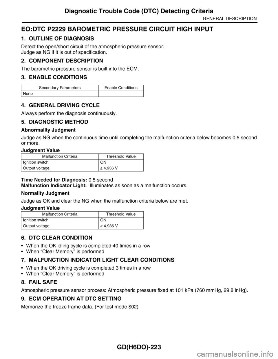
EO:DTC P2229 BAROMETRIC PRESSURE CIRCUIT HIGH INPUT
1. OUTLINE OF DIAGNOSIS
Detect the open/short circuit of the atmospheric pressure sensor.
Judge as NG if it is out of specification.
2. COMPONENT DESCRIPTION
The barometric pressure sensor is built into the ECM.
3. ENABLE CONDITIONS
4. GENERAL DRIVING CYCLE
Always perform the diagnosis continuously.
5. DIAGNOSTIC METHOD
Abnormality Judgment
Judge as NG when the continuous time until completing the malfunction criteria below becomes 0.5 second
or more.
Time Needed for Diagnosis: 0.5 second
Malfunction Indicator Light: Illuminates as soon as a malfunction occurs.
Normality Judgment
Judge as OK and clear the NG when the malfunction criteria below are met.
6. DTC CLEAR CONDITION
•When the OK idling cycle is completed 40 times in a row
•When “Clear Memory” is performed
7. MALFUNCTION INDICATOR LIGHT CLEAR CONDITIONS
•When the OK driving cycle is completed 3 times in a row
•When “Clear Memory” is performed
8. FAIL SAFE
Atmospheric pressure sensor process: Atmospheric pressure fixed at 101 kPa (760 mmHg, 29.8 inHg).
9. ECM OPERATION AT DTC SETTING
Memorize the freeze frame data. (For test mode $02)
Secondary Parameters Enable Conditions
None
Judgment Value
Malfunction Criteria Threshold Value
Ignition switch ON
Output voltage≥ 4.936 V
Judgment Value
Malfunction Criteria Threshold Value
Ignition switch ON
Output voltage < 4.936 V
Page 1837 of 2453
IG(H6DO)-2
General Description
IGNITION
1. General Description
A: SPECIFICATION
Item Specification
Ignition coil & ignitor ASSY
Typ e F K 0 14 0
Ignition system Independent ignition coil
Manufacturer Diamond Electric
Spar k p l ug
Manufacturer and type NGK: ILFR6B
Thread size (diameter, pitch, length) mm 14, 1.25, 26.5
Spark plug gap mm (in) 0.7 — 0.8 (0.028 — 0.031)
Electrode Iridium
Page 1838 of 2453
IG(H6DO)-3
General Description
IGNITION
B: COMPONENT
C: CAUTION
•Wear work clothing, including a cap, protective goggles and protective shoes during operation.
•Remove contamination including dirt and corrosion before removal, installation or disassembly.
•Keep the disassembled parts in order and protect them from dust and dirt.
•Before removal, installation or disassembly, be sure to clarify the failure. Avoid unnecessary removal, in-
stallation, disassembly and replacement.
•Be careful not to burn yourself, because each part on the vehicle is hot after running.
•Be sure to tighten fasteners including bolts and nuts to the specified torque.
•Place shop jacks or rigid racks at the specified points.
•Before disconnecting connectors of sensors or units, be sure to disconnect the ground cable from battery.
(1) Spark plug Tightening torque: N·m (kgf-m, ft-lb)
(2) Ignition coil & ignitor ASSY T1: 16 (1.6, 11.7)
T2: 21 (2.1, 15.2)
IG-00052
(1)
(1)
(2)
(2)
T1
T2
T2
T1
Page 1839 of 2453
IG(H6DO)-4
Spark Plug
IGNITION
2. Spark Plug
A: REMOVAL
CAUTION:
All spark plugs installed on an engine must be
of the same heat range.
Spark plug:
al Description.>
1. RH SIDE
1) Remove the collector cover.
2) Disconnect the ground cable from battery.
3) Remove the air cleaner case.
Case.>
4) Remove the bracket.
5) Disconnect the connector from ignition coil.
6) Remove the ignition coil.
NOTE:
Turn the #5 ignition coil to remove it.
7) Remove the spark plug with a spark plug socket.
2. LH SIDE
1) Remove the collector cover.
2) Remove the battery and battery carrier.
3) Remove the bracket.
4) Disconnect the connector from ignition coil.
5) Remove the ignition coil.
NOTE:
Turn the #6 ignition coil to remove it.
(A) Bracket
(B) Connector
IG-02004(B)
(A)
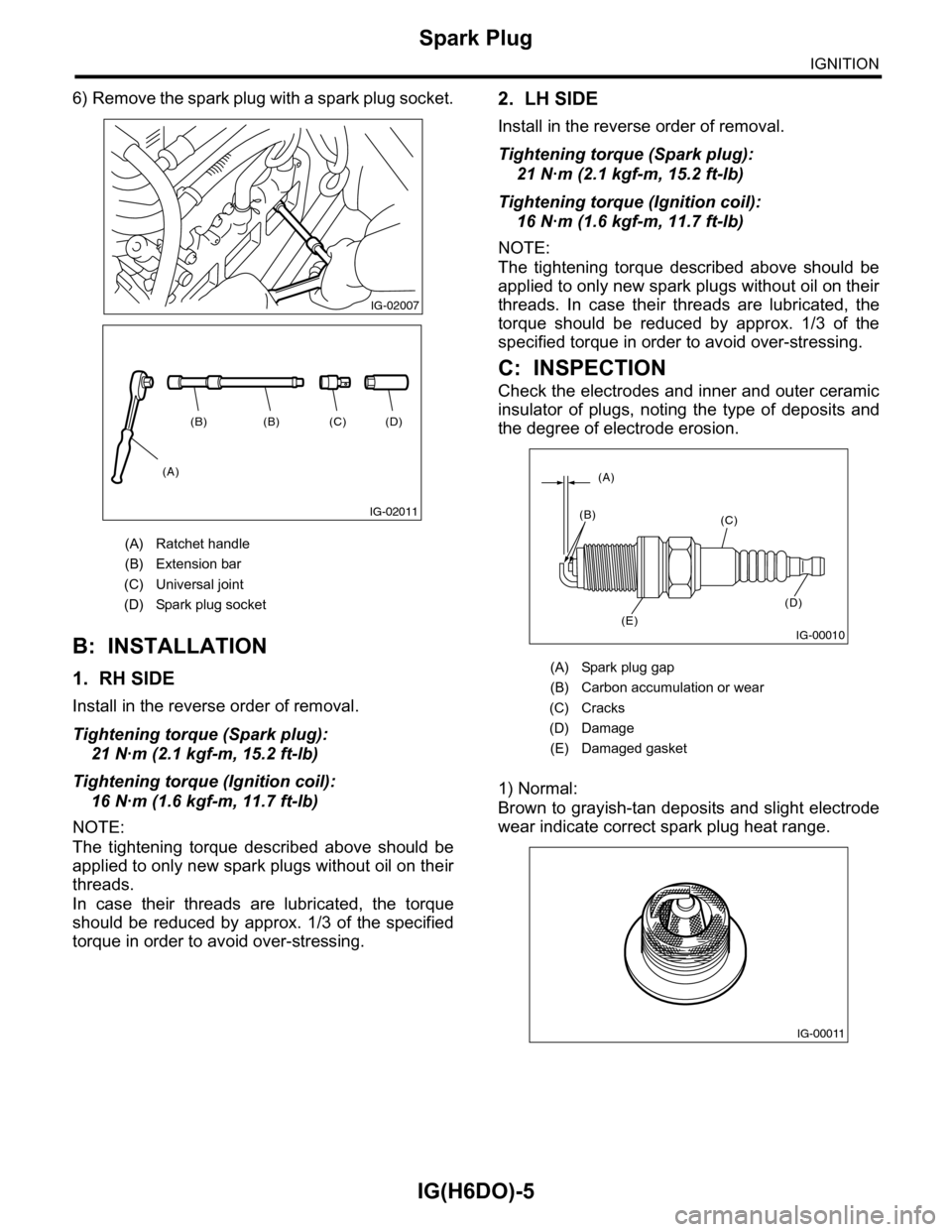
(A) Ratchet handle
(B) Extension bar
(C) Universal joint
(D) Spark plug socket
(A) Bracket
(B) Connector
IG-02005
(D)(C)(B)(B)
(A)
IG-02011
IG-02006
(A)
(B)
Page 1840 of 2453

IG(H6DO)-5
Spark Plug
IGNITION
6) Remove the spark plug with a spark plug socket.
B: INSTALLATION
1. RH SIDE
Install in the reverse order of removal.
Tightening torque (Spark plug):
21 N·m (2.1 kgf-m, 15.2 ft-lb)
Tightening torque (Ignition coil):
16 N·m (1.6 kgf-m, 11.7 ft-lb)
NOTE:
The tightening torque described above should be
applied to only new spark plugs without oil on their
threads.
In case their threads are lubricated, the torque
should be reduced by approx. 1/3 of the specified
torque in order to avoid over-stressing.
2. LH SIDE
Install in the reverse order of removal.
Tightening torque (Spark plug):
21 N·m (2.1 kgf-m, 15.2 ft-lb)
Tightening torque (Ignition coil):
16 N·m (1.6 kgf-m, 11.7 ft-lb)
NOTE:
The tightening torque described above should be
applied to only new spark plugs without oil on their
threads. In case their threads are lubricated, the
torque should be reduced by approx. 1/3 of the
specified torque in order to avoid over-stressing.
C: INSPECTION
Check the electrodes and inner and outer ceramic
insulator of plugs, noting the type of deposits and
the degree of electrode erosion.
1) Normal:
Brown to grayish-tan deposits and slight electrode
wear indicate correct spark plug heat range.
(A) Ratchet handle
(B) Extension bar
(C) Universal joint
(D) Spark plug socket
IG-02007
(D)(C)(B)(B)
(A)
IG-02011
(A) Spark plug gap
(B) Carbon accumulation or wear
(C) Cracks
(D) Damage
(E) Damaged gasket
IG-00010
(A)
(B)(C)
(D)
(E)
IG-00011
Page 1841 of 2453

IG(H6DO)-6
Spark Plug
IGNITION
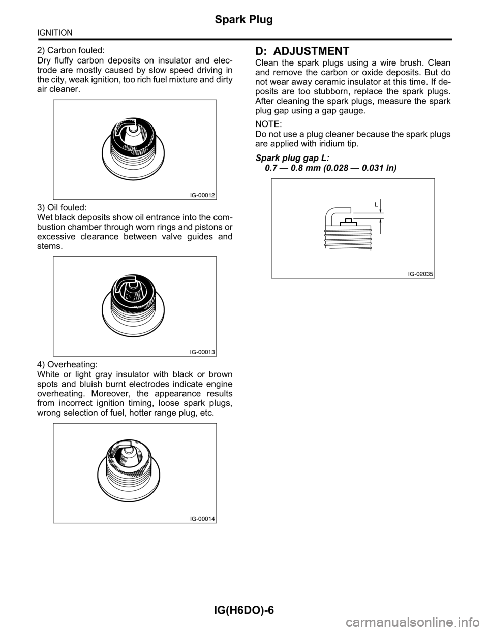
2) Carbon fouled:
Dry fluffy carbon deposits on insulator and elec-
trode are mostly caused by slow speed driving in
the city, weak ignition, too rich fuel mixture and dirty
air cleaner.
3) Oil fouled:
Wet black deposits show oil entrance into the com-
bustion chamber through worn rings and pistons or
excessive clearance between valve guides and
stems.
4) Overheating:
White or light gray insulator with black or brown
spots and bluish burnt electrodes indicate engine
overheating. Moreover, the appearance results
from incorrect ignition timing, loose spark plugs,
wrong selection of fuel, hotter range plug, etc.
D: ADJUSTMENT
Clean the spark plugs using a wire brush. Clean
and remove the carbon or oxide deposits. But do
not wear away ceramic insulator at this time. If de-
posits are too stubborn, replace the spark plugs.
After cleaning the spark plugs, measure the spark
plug gap using a gap gauge.
NOTE:
Do not use a plug cleaner because the spark plugs
are applied with iridium tip.
Spark plug gap L:
0.7 — 0.8 mm (0.028 — 0.031 in)
IG-00012
IG-00013
IG-00014
IG-02035
L
Page 1842 of 2453
IG(H6DO)-7
Ignition Coil & Ignitor Assembly
IGNITION
3. Ignition Coil & Ignitor Assem-
bly
A: REMOVAL
Direct ignition type has been adopted. Refer to
“Spark Plug” for removal procedure.
IG(H6DO)-4, REMOVAL, Spark Plug.>
B: INSTALLATION
Install in the reverse order of removal.
Tightening torque:
16 N·m (1.6 kgf-m, 11.7 ft-lb)
C: INSPECTION
For inspection procedure, refer to “Diagnostics for
Engine Starting Failure.”
63, IGNITION CONTROL SYSTEM, Diagnostics
for Engine Starting Failure.>