2009 SUBARU TRIBECA ignition
[x] Cancel search: ignitionPage 1893 of 2453
ME(H6DO)-27
Valve Clearance
MECHANICAL
8. Valve Clearance
A: INSPECTION
Inspection and adjustment of valve clearance
should be performed while engine is cold.
1) Set the vehicle on a lift.
2) Remove the collector cover.
3) Disconnect the ground cable from battery.
4) Lift-up the vehicle.
5) Remove the under cover.
6) Lower the vehicle.
7) When inspecting RH side cylinders:
(1) Remove the air intake duct and air cleaner
case.
(2) Remove the fuel tank protector (RH).
(3) Disconnect the connector of oil pressure
switch.
(4) Remove the ignition coil.
Assembly.>
(5) Remove the rocker cover (RH).
8) When inspecting LH side cylinders:
(1) Disconnect the battery cable, and then re-
move the battery and battery carrier.
(2) Disconnect the PCV hose and blow-by hose
from rocker cover (LH).
(3) Remove the fuel pipe protector (LH).
(4) Remove the ignition coil.
Assembly.>
(5) Remove the rocker cover (LH).
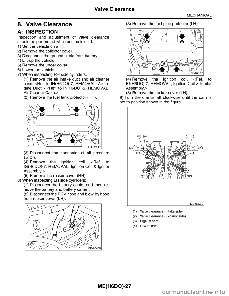
9) Turn the crankshaft clockwise until the cam is
set to position shown in the figure.
FU-02119
ME-00460
(1) Valve clearance (Intake side)
(2) Valve clearance (Exhaust side)
(3) High lift cam
(4) Low lift cam
FU-02117
ME-02565
(4)(3)(3)(4)
(1)
(2)
(1)
(2)
(23 )(23 )
Page 1956 of 2453
ME(H6DO)-90
Engine Noise
MECHANICAL
29.Engine Noise
A: INSPECTION
(NOTE*)
When disconnecting the fuel injector connector, the malfunction indicator light illuminates and DTC is stored in ECM memory.
Therefore, carry out the clear memory mode
mode
Ty p e o f s o u n d C o n d i t i o n P o s s i b l e c a u s e
Regular clicking soundSound increases as engine
speed increases.
•Valve mechanism is defective.
•Incorrect valve clearance
•Worn valve rocker
•Worn camshaft
•Broken valve spring
•Trouble of tappet
Heavy and dull clankOil pressure is low.•Worn camshaft main bearing
•Worn connecting rod bearing (large end)
Oil pressure is normal. Damaged engine mounting
High-pitched clank
Sound is noticeable when
accelerating with an overload
condition.
•Ignition timing advanced
•Accumulation of carbon inside combustion chamber
•Wrong spark plug
•Improper gasoline
Clank when engine speed is
between 1,000 and 2,000
rpms.
Sound is reduced when fuel
injector connector of noisy cyl-
inder is disconnected.
(NOTE*)
•Worn crankshaft main bearing
•Worn bearing at crankshaft end of connecting rod
Knocking sound when engine
is operating under idling speed
and engine is warm
Sound is reduced when fuel
injector connector of noisy cyl-
inder is disconnected.
(NOTE*)
•Worn cylinder liner and piston ring
•Broken or stuck piston ring
•Worn piston pin and hole at piston end of connecting rod
Sound is not reduced if each
fuel injector connector is dis-
connected in turn. (NOTE*)
•Unusually worn valve lifter
•Worn cam gear
•Worn camshaft journal bore in crankcase
Squeaky sound — • Insufficient generator lubrication
Rubbing sound — • Poor contact of generator brush and rotor
Gear scream when starting
engine—•Defective ignition starter switch
•Worn gear and starter pinion
Sound like polishing glass with
a dry cloth—•Loose drive belt
•Defective water pump shaft
Hissing sound —•Insufficient compression
•Air leakage in air intake system, hose, connection or manifold
Timing belt noise —•Loose timing belt
•Belt contacting with case/adjacent part
Va l ve t a p p e t n o i s e —•Incorrect valve clearance
•Trouble of tappet
Page 1983 of 2453
SC(H6DO)-25
Battery
STARTING/CHARGING SYSTEMS
4. Battery
A: REMOVAL
1) Disconnect the positive (+) terminal after discon-
necting the negative (–) terminal of battery.
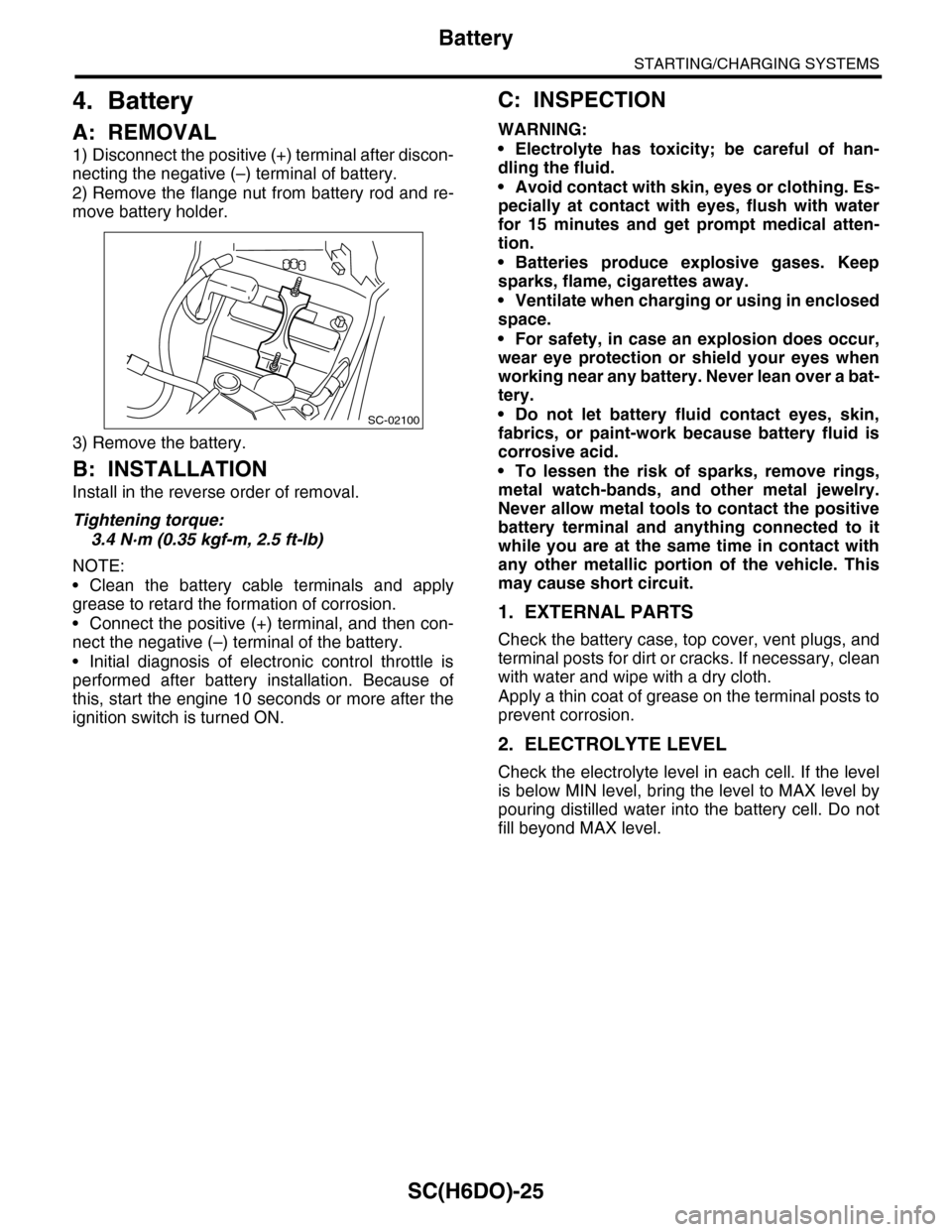
2) Remove the flange nut from battery rod and re-
move battery holder.
3) Remove the battery.
B: INSTALLATION
Install in the reverse order of removal.
Tightening torque:
3.4 N·m (0.35 kgf-m, 2.5 ft-lb)
NOTE:
•Clean the battery cable terminals and apply
grease to retard the formation of corrosion.
•Connect the positive (+) terminal, and then con-
nect the negative (–) terminal of the battery.
•Initial diagnosis of electronic control throttle is
performed after battery installation. Because of
this, start the engine 10 seconds or more after the
ignition switch is turned ON.
C: INSPECTION
WARNING:
•Electrolyte has toxicity; be careful of han-
dling the fluid.
•Avoid contact with skin, eyes or clothing. Es-
pecially at contact with eyes, flush with water
for 15 minutes and get prompt medical atten-
tion.
•Batteries produce explosive gases. Keep
sparks, flame, cigarettes away.
•Ventilate when charging or using in enclosed
space.
•For safety, in case an explosion does occur,
wear eye protection or shield your eyes when
working near any battery. Never lean over a bat-
tery.
•Do not let battery fluid contact eyes, skin,
fabrics, or paint-work because battery fluid is
corrosive acid.
•To lessen the risk of sparks, remove rings,
metal watch-bands, and other metal jewelry.
Never allow metal tools to contact the positive
battery terminal and anything connected to it
while you are at the same time in contact with
any other metallic portion of the vehicle. This
may cause short circuit.
1. EXTERNAL PARTS
Check the battery case, top cover, vent plugs, and
terminal posts for dirt or cracks. If necessary, clean
with water and wipe with a dry cloth.
Apply a thin coat of grease on the terminal posts to
prevent corrosion.
2. ELECTROLYTE LEVEL
Check the electrolyte level in each cell. If the level
is below MIN level, bring the level to MAX level by
pouring distilled water into the battery cell. Do not
fill beyond MAX level.
SC-02100
Page 1992 of 2453

PM-9
Spark Plug
PERIODIC MAINTENANCE SERVICES
5. Spark Plug
A: REPLACEMENT
1) Remove the battery and battery carrier.
2) Remove the air cleaner case.
3) Detach the connector from ignition coil.
4) Remove the ignition coil.
5) Remove the spark plug with a spark plug socket.
6) Tighten the new spark plug lightly with hand, and
then secure with a spark plug socket to the speci-
fied torque.
Recommended spark plug:
NGK: ILFR6B
Tightening torque:
21 N·m (2.1 kgf-m, 15.2 ft-lb)
7) Tighten the ignition coil.
Tightening torque:
16 N·m (1.6 kgf-m, 11.7 ft-lb)
NOTE:
•Be sure to place the gasket between the cylinder
head and spark plug.
•If the torque wrench is not available, tighten the
spark plug until gasket contacts cylinder head; then
tighten further 1/4 to 1/2 turns.
(A) Bracket
(B) Connector
IG-02004(B)
(A)
PM-00112
Page 2015 of 2453
PM-32
Supplemental Restraint System
PERIODIC MAINTENANCE SERVICES
22.Supplemental Restraint System
A: INSPECTION
Check the airbag system in accordance with the result of the self-diagnosis.
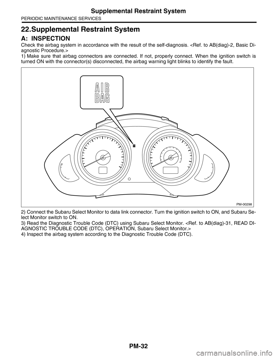
1) Make sure that airbag connectors are connected. If not, properly connect. When the ignition switch is
turned ON with the connector(s) disconnected, the airbag warning light blinks to identify the fault.
2) Connect the Subaru Select Monitor to data link connector. Turn the ignition switch to ON, and Subaru Se-
lect Monitor switch to ON.
3) Read the Diagnostic Trouble Code (DTC) using Subaru Select Monitor.
4) Inspect the airbag system according to the Diagnostic Trouble Code (DTC).
PM-00298
Page 2119 of 2453
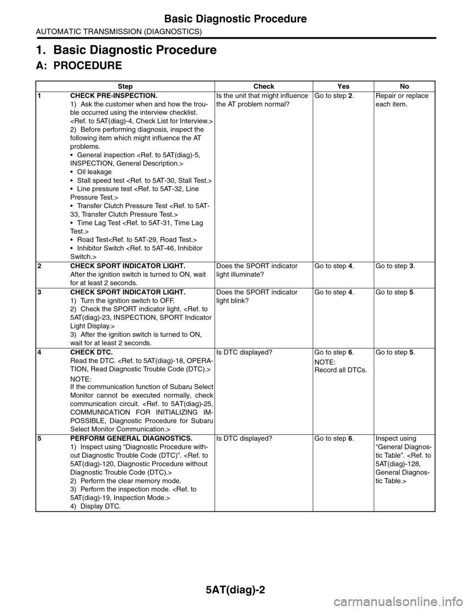
5AT(diag)-2
Basic Diagnostic Procedure
AUTOMATIC TRANSMISSION (DIAGNOSTICS)
1. Basic Diagnostic Procedure
A: PROCEDURE
Step Check Yes No
1CHECK PRE-INSPECTION.
1) Ask the customer when and how the trou-
ble occurred using the interview checklist.
2) Before performing diagnosis, inspect the
following item which might influence the AT
problems.
•General inspection
•Oil leakage
•Stall speed test
•Line pressure test
•Transfer Clutch Pressure Test
•Time Lag Test
•Road Test
•Inhibitor Switch
Is the unit that might influence
the AT problem normal?
Go to step 2.Repair or replace
each item.
2CHECK SPORT INDICATOR LIGHT.
After the ignition switch is turned to ON, wait
for at least 2 seconds.
Does the SPORT indicator
light illuminate?
Go to step 4.Go to step 3.
3CHECK SPORT INDICATOR LIGHT.
1) Turn the ignition switch to OFF.
2) Check the SPORT indicator light.
Light Display.>
3) After the ignition switch is turned to ON,
wait for at least 2 seconds.
Does the SPORT indicator
light blink?
Go to step 4.Go to step 5.
4CHECK DTC.
Read the DTC.
NOTE:If the communication function of Subaru Select
Monitor cannot be executed normally, check
communication circuit.
POSSIBLE, Diagnostic Procedure for Subaru
Select Monitor Communication.>
Is DTC displayed? Go to step 6.
NOTE:
Record all DTCs.
Go to step 5.
5PERFORM GENERAL DIAGNOSTICS.
1) Inspect using “Diagnostic Procedure with-
out Diagnostic Trouble Code (DTC)”.
Diagnostic Trouble Code (DTC).>
2) Perform the clear memory mode.
3) Perform the inspection mode.
4) Display DTC.
Is DTC displayed? Go to step 6.Inspect using
“General Diagnos-
tic Table”.
General Diagnos-
tic Table.>
Page 2128 of 2453
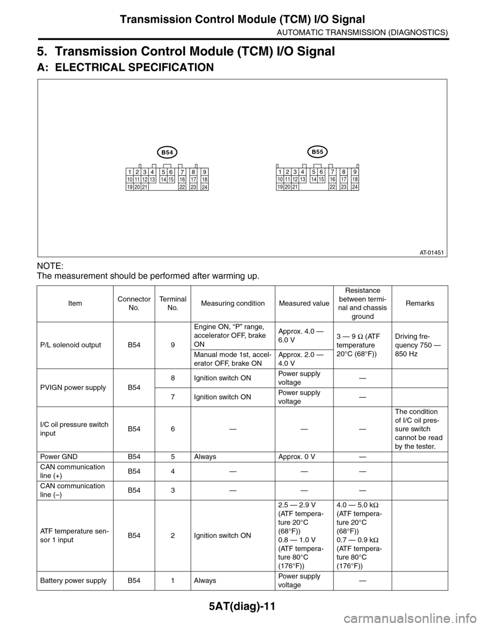
5AT(diag)-11
Transmission Control Module (TCM) I/O Signal
AUTOMATIC TRANSMISSION (DIAGNOSTICS)
5. Transmission Control Module (TCM) I/O Signal
A: ELECTRICAL SPECIFICATION
NOTE:
The measurement should be performed after warming up.
ItemConnector
No.
Te r m i n a l
No.Measuring condition Measured value
Resistance
between termi-
nal and chassis
ground
Remarks
P/L solenoid output B54 9
Engine ON, “P” range,
accelerator OFF, brake
ON
Approx. 4.0 —
6.0 V3 — 9 Ω (ATF
temperature
20°C (68°F))
Driving fre-
quency 750 —
850 HzManual mode 1st, accel-
erator OFF, brake ON
Approx. 2.0 —
4.0 V
PVIGN power supply B54
8Ignition switch ONPow er s up p ly
voltage—
7Ignition switch ONPow er s up p ly
voltage—
I/C oil pressure switch
inputB54 6 — — —
The condition
of I/C oil pres-
sure switch
cannot be read
by the tester.
Pow er G N D B 5 4 5 A lways A pp r ox . 0 V —
CAN communication
line (+)B54 4 — — —
CAN communication
line (–)B54 3 — — —
AT F t e m p e r a t u r e s e n -
sor 1 inputB54 2 Ignition switch ON
2.5 — 2.9 V
(ATF tempera-
ture 20°C
(68°F))
0.8 — 1.0 V
(ATF tempera-
ture 80°C
(176°F))
4.0 — 5.0 kΩ
(ATF tempera-
ture 20°C
(68°F))
0.7 — 0.9 kΩ
(ATF tempera-
ture 80°C
(176°F))
Battery power supply B54 1 AlwaysPow er s up p ly
voltage—
AT-01451
12341011 121920 21135614 1578916 17 1822 23 24
12789563410 11 1219 20 2113 14 15 16 17 18222324
B55B54
Page 2129 of 2453
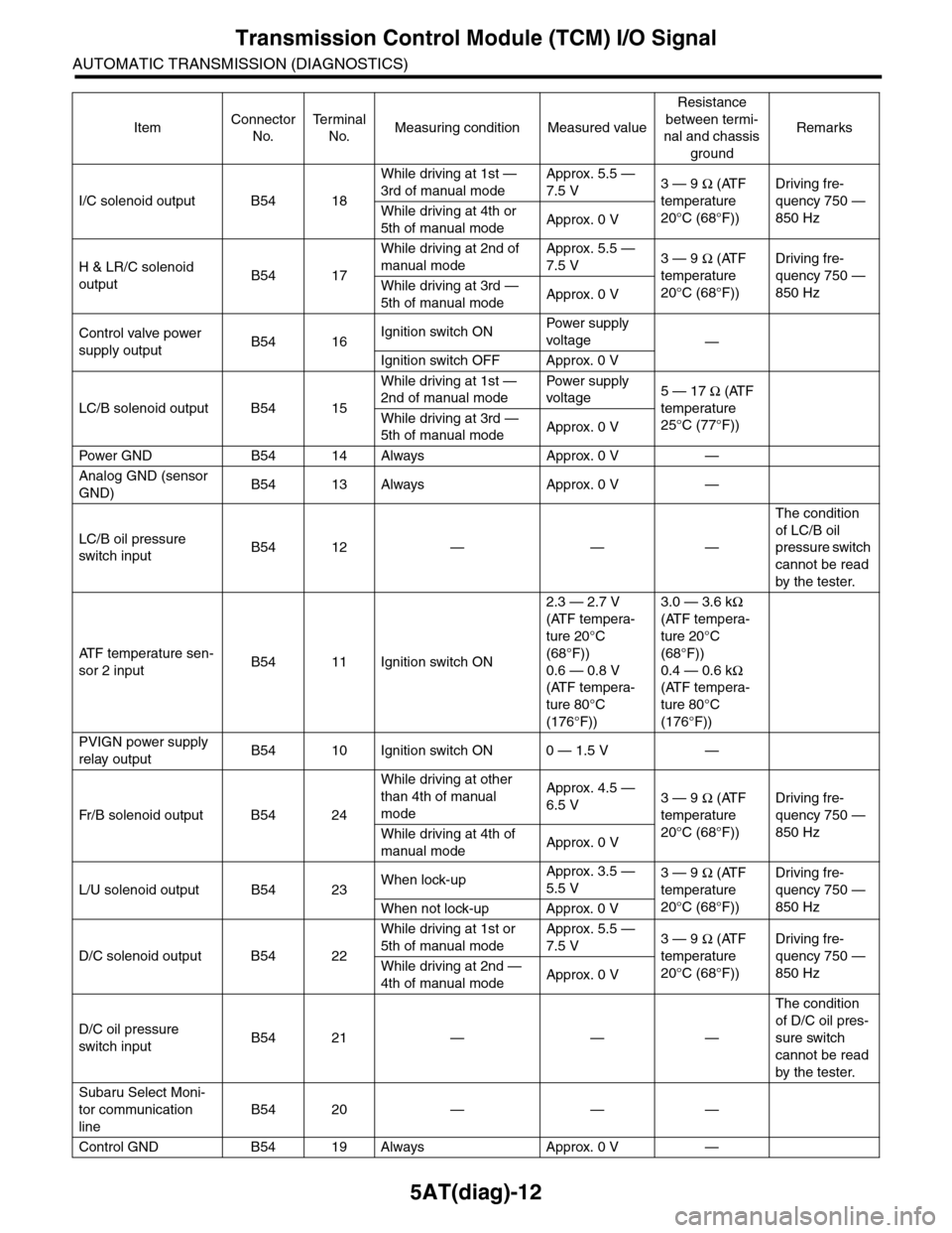
5AT(diag)-12
Transmission Control Module (TCM) I/O Signal
AUTOMATIC TRANSMISSION (DIAGNOSTICS)
I/C solenoid output B54 18
While driving at 1st —
3rd of manual mode
Approx. 5.5 —
7.5 V3 — 9 Ω (ATF
temperature
20°C (68°F))
Driving fre-
quency 750 —
850 HzWhile driving at 4th or
5th of manual modeApprox. 0 V
H & LR/C solenoid
outputB54 17
While driving at 2nd of
manual mode
Approx. 5.5 —
7.5 V3 — 9 Ω (ATF
temperature
20°C (68°F))
Driving fre-
quency 750 —
850 HzWhile driving at 3rd —
5th of manual modeApprox. 0 V
Control valve power
supply outputB54 16Ignition switch ONPow er s up p ly
voltage—
Ignition switch OFF Approx. 0 V
LC/B solenoid output B54 15
While driving at 1st —
2nd of manual mode
Pow er s up p ly
voltage5 — 17 Ω (ATF
temperature
25°C (77°F))
While driving at 3rd —
5th of manual modeApprox. 0 V
Pow er GN D B 5 4 1 4 A lways A pp r ox . 0 V —
Analog GND (sensor
GND)B54 13 Always Approx. 0 V —
LC/B oil pressure
switch inputB54 12 — — —
The condition
of LC/B oil
pressure switch
cannot be read
by the tester.
AT F t e m p e r a t u r e s e n -
sor 2 inputB54 11 Ignition switch ON
2.3 — 2.7 V
(ATF tempera-
ture 20°C
(68°F))
0.6 — 0.8 V
(ATF tempera-
ture 80°C
(176°F))
3.0 — 3.6 kΩ
(ATF tempera-
ture 20°C
(68°F))
0.4 — 0.6 kΩ
(ATF tempera-
ture 80°C
(176°F))
PVIGN power supply
relay outputB54 10 Ignition switch ON 0 — 1.5 V —
Fr / B so le n oi d o u tp u t B 5 4 2 4
While driving at other
than 4th of manual
mode
Approx. 4.5 —
6.5 V3 — 9 Ω (ATF
temperature
20°C (68°F))
Driving fre-
quency 750 —
850 HzWhile driving at 4th of
manual modeApprox. 0 V
L/U solenoid output B54 23When lock-upApprox. 3.5 —
5.5 V3 — 9 Ω (ATF
temperature
20°C (68°F))
Driving fre-
quency 750 —
850 HzWhen not lock-up Approx. 0 V
D/C solenoid output B54 22
While driving at 1st or
5th of manual mode
Approx. 5.5 —
7.5 V3 — 9 Ω (ATF
temperature
20°C (68°F))
Driving fre-
quency 750 —
850 HzWhile driving at 2nd —
4th of manual modeApprox. 0 V
D/C oil pressure
switch inputB54 21 — — —
The condition
of D/C oil pres-
sure switch
cannot be read
by the tester.
Subaru Select Moni-
tor communication
line
B54 20 — — —
Control GND B54 19 Always Approx. 0 V —
ItemConnector
No.
Te r m i n a l
No.Measuring condition Measured value
Resistance
between termi-
nal and chassis
ground
Remarks