Page 1843 of 2453
IG(H6DO)-8
Ignition Coil & Ignitor Assembly
IGNITION
Page 1854 of 2453
LU(H6DO)-5
Oil Pressure System
LUBRICATION
2. Oil Pressure System
A: WIRING DIAGRAM
LU-02159
E
i3
B38
i126
i127
B21
E2
14
E11
NO.5SBF-6MAIN SBF
B72
36
B10
i10
31
A4A3
B72
1345621234 5678910 11 12 13 14 15 16 17 18 19 20
B38B21
123412131415567816171819910 1120212223 24 25 2627 28 29 3031 32 33
3534 37363938 41404342 4445 47464948 51505352 54
A:
i11B:
BATTERYIGNITIONSWITCH
COMBINATIONMETER
OIL PRESSUREWA R N I N G L I G H T
OIL PRESSURESWITCH
1*1*
2*
i127
i126
123456789101112
1234567891011121314
i11B:
123456789101112131415161718192021222324252627282930
i10A:
2* :TERMINAL NO. OPTIONAL ARRANGEMENT AMONG 10, 11 AND 12
1*: TERMINAL NO. OPTIONAL ARRANGEMENT AMONG 7, 8 AND 9
Page 1855 of 2453
LU(H6DO)-6
Oil Pressure System
LUBRICATION
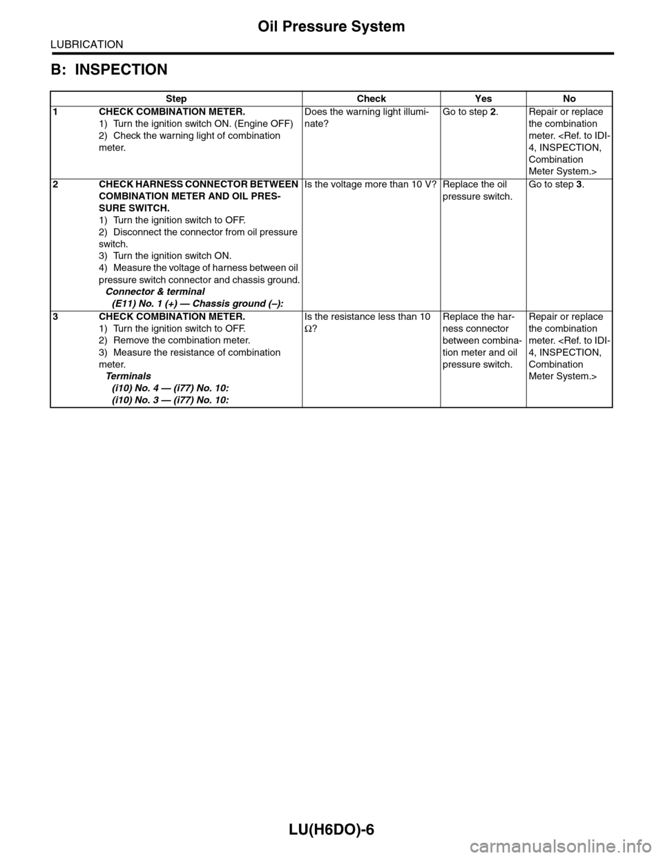
B: INSPECTION
Step Check Yes No
1CHECK COMBINATION METER.
1) Turn the ignition switch ON. (Engine OFF)
2) Check the warning light of combination
meter.
Does the warning light illumi-
nate?
Go to step 2.Repair or replace
the combination
meter.
4, INSPECTION,
Combination
Meter System.>
2CHECK HARNESS CONNECTOR BETWEEN
COMBINATION METER AND OIL PRES-
SURE SWITCH.
1) Turn the ignition switch to OFF.
2) Disconnect the connector from oil pressure
switch.
3) Turn the ignition switch ON.
4) Measure the voltage of harness between oil
pressure switch connector and chassis ground.
Connector & terminal
(E11) No. 1 (+) — Chassis ground (–):
Is the voltage more than 10 V? Replace the oil
pressure switch.
Go to step 3.
3CHECK COMBINATION METER.
1) Turn the ignition switch to OFF.
2) Remove the combination meter.
3) Measure the resistance of combination
meter.
Te r m i n a l s
(i10) No. 4 — (i77) No. 10:
(i10) No. 3 — (i77) No. 10:
Is the resistance less than 10
Ω?
Replace the har-
ness connector
between combina-
tion meter and oil
pressure switch.
Repair or replace
the combination
meter.
4, INSPECTION,
Combination
Meter System.>
Page 1868 of 2453
ME(H6DO)-2
General Description
MECHANICAL
1. General Description
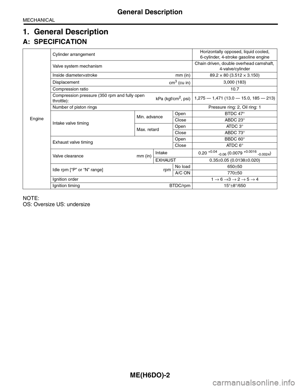
A: SPECIFICATION
NOTE:
OS: Oversize US: undersize
Engine
Cylinder arrangementHorizontally opposed, liquid cooled,
6-cylinder, 4-stroke gasoline engine
Va l ve s y s t e m m e c h a n i s mChain driven, double overhead camshaft,
4-valve/cylinder
Inside diameter×stroke mm (in) 89.2 × 80 (3.512 × 3.150)
Displacementcm3 (cu in)3,000 (183)
Compression ratio10.7
Compression pressure (350 rpm and fully open
throttle):kPa (kgf/cm2, psi)1,275 — 1,471 (13.0 — 15.0, 185 — 213)
Number of piston rings Pressure ring: 2, Oil ring: 1
Intake valve timing
Min. advanceOpen BTDC 47°
Close ABDC 23°
Max. retardOpen ATDC 3°
Close ABDC 73°
Exhaust valve timingOpen BBDC 60°
Close ATDC 6°
Va l ve c l e a r a n c e m m ( i n )Intake0.20 +0.04 -0.06 (0.0079 +0.0016 -0.0024)
EXHAUST 0.35±0.05 (0.0138±0.020)
Idle rpm [“P” or “N” range] rpmNo load 650±50
A/C ON 770±50
Ignition order 1 → 6 →3 → 2 → 5 → 4
Ignition timing BTDC/rpm 15°±8°/650
Page 1887 of 2453
ME(H6DO)-21
Compression
MECHANICAL
2. Compression
A: INSPECTION
CAUTION:
After warming-up, engine becomes very hot. Be
careful not to burn yourself during measure-
ment.
1) After warming-up the engine, turn the ignition
switch to OFF.
2) Make sure that the battery is fully charged.
3) Release the fuel pressure.
PRESSURE, PROCEDURE, Fuel.>
4) Remove all the spark plugs.
4, REMOVAL, Spark Plug.>
5) Check the starter motor for satisfactory perfor-
mance and operation.
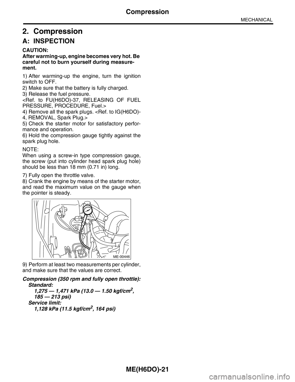
6) Hold the compression gauge tightly against the
spark plug hole.
NOTE:
When using a screw-in type compression gauge,
the screw (put into cylinder head spark plug hole)
should be less than 18 mm (0.71 in) long.
7) Fully open the throttle valve.
8) Crank the engine by means of the starter motor,
and read the maximum value on the gauge when
the pointer is steady.
9) Perform at least two measurements per cylinder,
and make sure that the values are correct.
Compression (350 rpm and fully open throttle):
Standard:
1,275 — 1,471 kPa (13.0 — 1.50 kgf/cm2,
185 — 213 psi)
Service limit:
1,128 kPa (11.5 kgf/cm2, 164 psi)
ME-00446
Page 1888 of 2453
ME(H6DO)-22
Idle Speed
MECHANICAL
3. Idle Speed
A: INSPECTION
1) Before checking the idle speed, check the fol-
lowing item:
(1) Check the air cleaner element is free from
clogging, ignition timing is correct, spark plugs
are in good condition, and hoses are connected
properly.
(2) Check the malfunction indicator light does
not illuminate.
2) Idle the engine.
3) Stop the engine, and turn the ignition switch to
OFF.
4) Insert the cartridge to Subaru Select Monitor.
5) Connect the Subaru Select Monitor to data link
connector.
6) Turn the ignition switch to ON and Subaru Select
Monitor switch to ON.
7) Select {Each System Check} in Main Menu.
8) Select {Engine} in Selection Menu.
9) Select {Current Data Display & Save} in Engine
Control System Diagnosis.
10) Select {Data Display} in Data Display Menu.
11) Start the engine, and read the engine idle
speed.
12) Check the idle speed when no-loaded. (Head-
light, heater fan, rear defroster, radiator fan, A/C
and etc. are OFF)
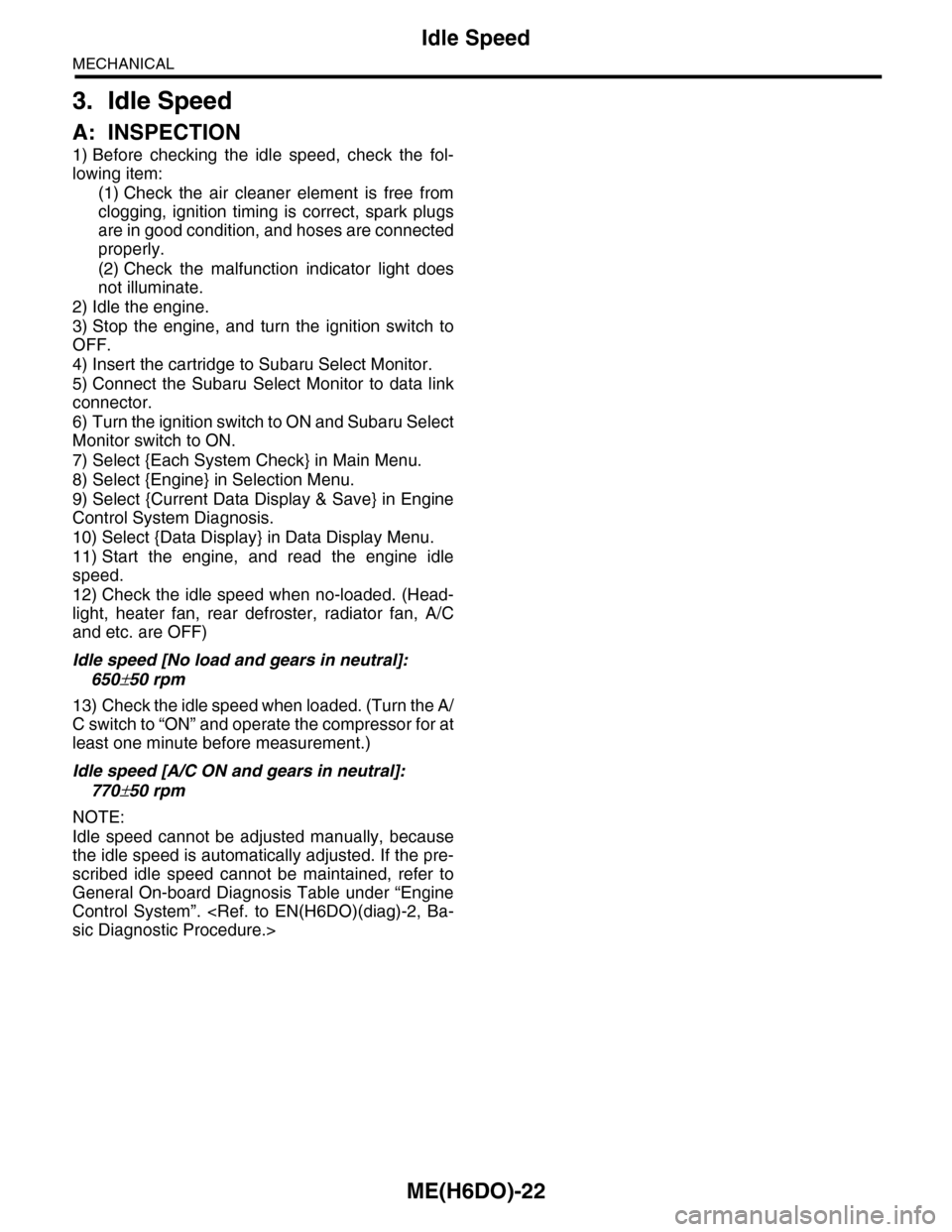
Idle speed [No load and gears in neutral]:
650±50 rpm
13) Check the idle speed when loaded. (Turn the A/
C switch to “ON” and operate the compressor for at
least one minute before measurement.)
Idle speed [A/C ON and gears in neutral]:
770±50 rpm
NOTE:
Idle speed cannot be adjusted manually, because
the idle speed is automatically adjusted. If the pre-
scribed idle speed cannot be maintained, refer to
General On-board Diagnosis Table under “Engine
Control System”.
sic Diagnostic Procedure.>
Page 1889 of 2453
ME(H6DO)-23
Ignition Timing
MECHANICAL
4. Ignition Timing
A: INSPECTION
CAUTION:
After warming-up, engine becomes very hot. Be
careful not to burn yourself at measurement.
1) Before checking the ignition timing, check the
following item:
(1) Check the air cleaner element is free from
clogging, spark plugs are in good condition, and
hoses are connected properly.
(2) Check the malfunction indicator light does
not illuminate.
2) Idle the engine.
3) Stop the engine, and turn the ignition switch to
OFF.
4) Insert the cartridge to Subaru Select Monitor.
5) Connect the Subaru Select Monitor to data link
connector.
6) Turn the ignition switch to ON and Subaru Select
Monitor switch to ON.
7) Select {Each System Check} in Main Menu.
8) Select {Engine} in Selection Menu.
9) Select {Current Data Display & Save} in Engine
Control System Diagnosis.
10) Select {Data Display} in Data Display Menu.
11) Start the engine and check the ignition timing at
idle speed.
Ignition timing [BTDC/rpm]:
15°±8°/650
If the timing is not correct, check the ignition control
system. Refer to Engine Control System.
EN(H6DO)(diag)-2, Basic Diagnostic Procedure.>
Page 1890 of 2453
ME(H6DO)-24
Intake Manifold Vacuum
MECHANICAL
5. Intake Manifold Vacuum
A: INSPECTION
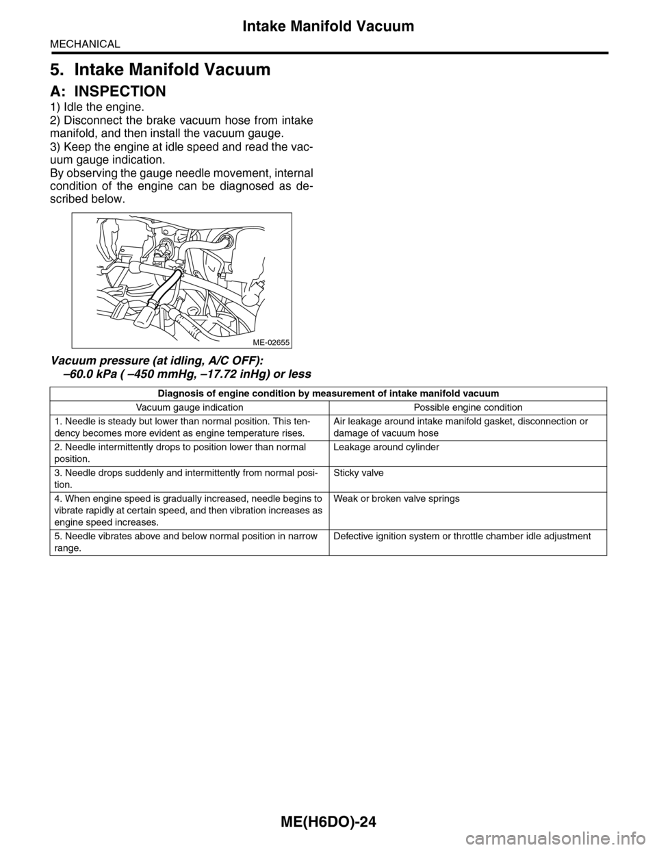
1) Idle the engine.
2) Disconnect the brake vacuum hose from intake
manifold, and then install the vacuum gauge.
3) Keep the engine at idle speed and read the vac-
uum gauge indication.
By observing the gauge needle movement, internal
condition of the engine can be diagnosed as de-
scribed below.
Vacuum pressure (at idling, A/C OFF):
–60.0 kPa ( –450 mmHg, –17.72 inHg) or less
ME-02655
Diagnosis of engine condition by measurement of intake manifold vacuum
Va c u u m g a u g e i n d i c a t i o n Po s s i bl e e n g i n e c o n d i t i o n
1. Needle is steady but lower than normal position. This ten-
dency becomes more evident as engine temperature rises.
Air leakage around intake manifold gasket, disconnection or
damage of vacuum hose
2. Needle intermittently drops to position lower than normal
position.
Leakage around cylinder
3. Needle drops suddenly and intermittently from normal posi-
tion.
Sticky valve
4. When engine speed is gradually increased, needle begins to
vibrate rapidly at certain speed, and then vibration increases as
engine speed increases.
Weak or broken valve spr ings
5. Needle vibrates above and below normal position in narrow
range.
Defective ignition system or throttle chamber idle adjustment