2009 SUBARU TRIBECA steering wheel
[x] Cancel search: steering wheelPage 1069 of 2453
VDC(diag)-77
Diagnostic Procedure with Diagnostic Trouble Code (DTC)
VEHICLE DYNAMICS CONTROL (VDC) (DIAGNOSTICS)
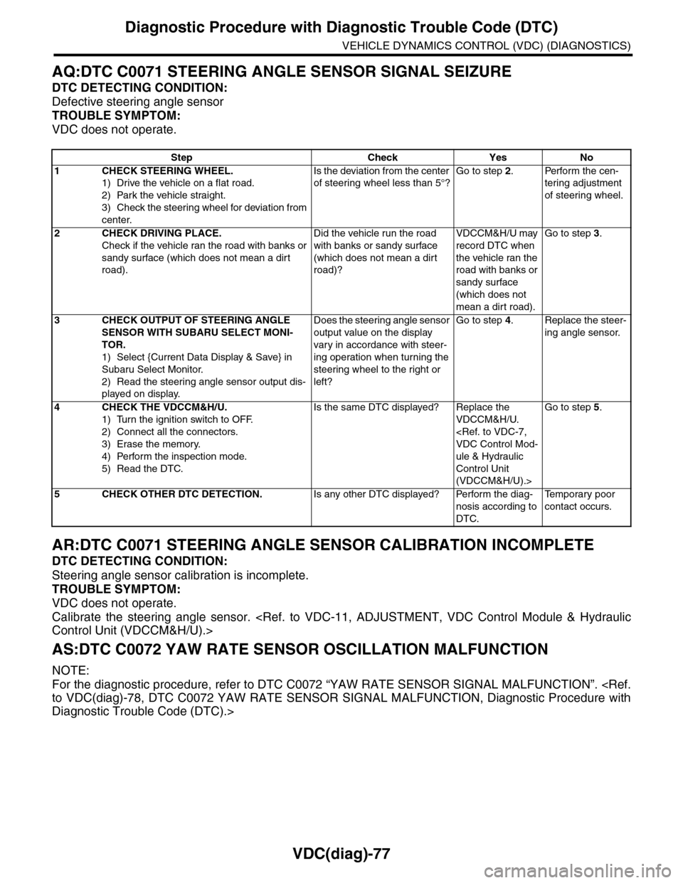
AQ:DTC C0071 STEERING ANGLE SENSOR SIGNAL SEIZURE
DTC DETECTING CONDITION:
Defective steering angle sensor
TROUBLE SYMPTOM:
VDC does not operate.
AR:DTC C0071 STEERING ANGLE SENSOR CALIBRATION INCOMPLETE
DTC DETECTING CONDITION:
Steering angle sensor calibration is incomplete.
TROUBLE SYMPTOM:
VDC does not operate.
Calibrate the steering angle sensor.
AS:DTC C0072 YAW RATE SENSOR OSCILLATION MALFUNCTION
NOTE:
For the diagnostic procedure, refer to DTC C0072 “YAW RATE SENSOR SIGNAL MALFUNCTION”.
Diagnostic Trouble Code (DTC).>
Step Check Yes No
1CHECK STEERING WHEEL.
1) Drive the vehicle on a flat road.
2) Park the vehicle straight.
3) Check the steering wheel for deviation from
center.
Is the deviation from the center
of steering wheel less than 5°?
Go to step 2.Perform the cen-
tering adjustment
of steering wheel.
2CHECK DRIVING PLACE.
Check if the vehicle ran the road with banks or
sandy surface (which does not mean a dirt
road).
Did the vehicle run the road
with banks or sandy surface
(which does not mean a dirt
road)?
VDCCM&H/U may
record DTC when
the vehicle ran the
road with banks or
sandy surface
(which does not
mean a dirt road).
Go to step 3.
3CHECK OUTPUT OF STEERING ANGLE
SENSOR WITH SUBARU SELECT MONI-
TOR.
1) Select {Current Data Display & Save} in
Subaru Select Monitor.
2) Read the steering angle sensor output dis-
played on display.
Does the steering angle sensor
output value on the display
var y in accordance with steer-
ing operation when turning the
steering wheel to the right or
left?
Go to step 4.Replace the steer-
ing angle sensor.
4CHECK THE VDCCM&H/U.
1) Turn the ignition switch to OFF.
2) Connect all the connectors.
3) Erase the memory.
4) Perform the inspection mode.
5) Read the DTC.
Is the same DTC displayed? Replace the
VDCCM&H/U.
ule & Hydraulic
Control Unit
(VDCCM&H/U).>
Go to step 5.
5CHECK OTHER DTC DETECTION.Is any other DTC displayed? Perform the diag-
nosis according to
DTC.
Te m p o r a r y p o o r
contact occurs.
Page 1079 of 2453
VDC(diag)-87
General Diagnostic Table
VEHICLE DYNAMICS CONTROL (VDC) (DIAGNOSTICS)
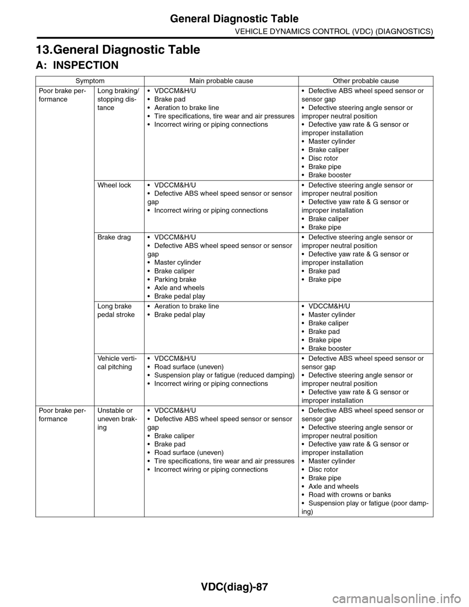
13.General Diagnostic Table
A: INSPECTION
Symptom Main probable cause Other probable cause
Po or b rake pe r -
for mance
Long braking/
stopping dis-
tance
•VDCCM&H/U
•Brake pad
•Aeration to brake line
•Tire specifications, tire wear and air pressures
•Incorrect wiring or piping connections
•Defective ABS wheel speed sensor or
sensor gap
•Defective steering angle sensor or
improper neutral position
•Defective yaw rate & G sensor or
improper installation
•Master cylinder
•Brake caliper
•Disc rotor
•Brake pipe
•Brake booster
Wheel lock • VDCCM&H/U
•Defective ABS wheel speed sensor or sensor
gap
•Incorrect wiring or piping connections
•Defective steering angle sensor or
improper neutral position
•Defective yaw rate & G sensor or
improper installation
•Brake caliper
•Brake pipe
Brake drag • VDCCM&H/U
•Defective ABS wheel speed sensor or sensor
gap
•Master cylinder
•Brake caliper
•Parking brake
•Axle and wheels
•Brake pedal play
•Defective steering angle sensor or
improper neutral position
•Defective yaw rate & G sensor or
improper installation
•Brake pad
•Brake pipe
Long brake
pedal stroke
•Aeration to brake line
•Brake pedal play
•VDCCM&H/U
•Master cylinder
•Brake caliper
•Brake pad
•Brake pipe
•Brake booster
Ve h i c l e v e r t i -
cal pitching
•VDCCM&H/U
•Road surface (uneven)
•Suspension play or fatigue (reduced damping)
•Incorrect wiring or piping connections
•Defective ABS wheel speed sensor or
sensor gap
•Defective steering angle sensor or
improper neutral position
•Defective yaw rate & G sensor or
improper installation
Po or b rake pe r -
for mance
Unstable or
uneven brak-
ing
•VDCCM&H/U
•Defective ABS wheel speed sensor or sensor
gap
•Brake caliper
•Brake pad
•Road surface (uneven)
•Tire specifications, tire wear and air pressures
•Incorrect wiring or piping connections
•Defective ABS wheel speed sensor or
sensor gap
•Defective steering angle sensor or
improper neutral position
•Defective yaw rate & G sensor or
improper installation
•Master cylinder
•Disc rotor
•Brake pipe
•Axle and wheels
•Road with crowns or banks
•Suspension play or fatigue (poor damp-
ing)
Page 1080 of 2453
VDC(diag)-88
General Diagnostic Table
VEHICLE DYNAMICS CONTROL (VDC) (DIAGNOSTICS)
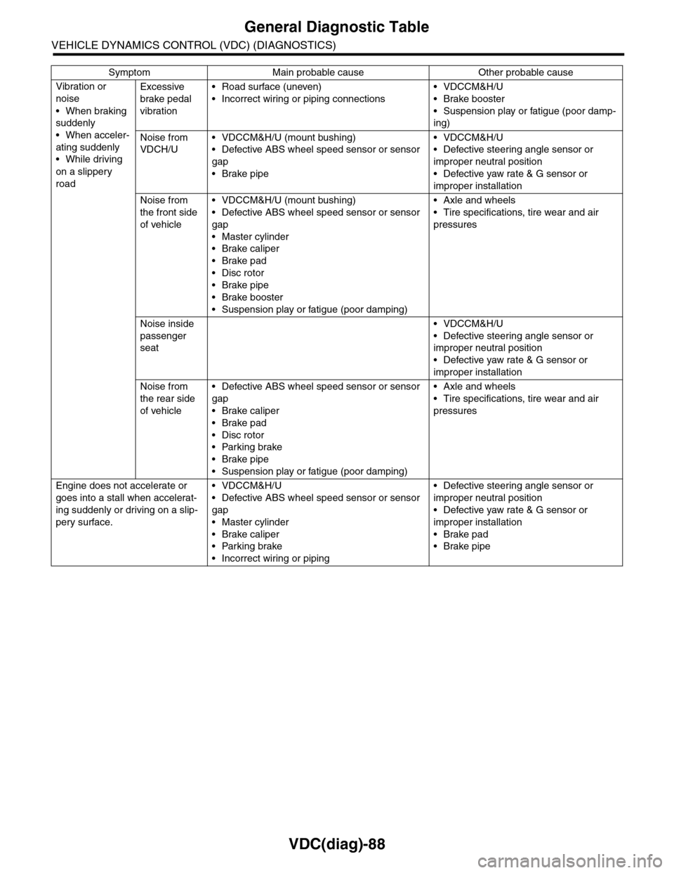
Vibration or
noise
•When braking
suddenly
•When acceler-
ating suddenly
•While driving
on a slippery
road
Excessive
brake pedal
vibration
•Road surface (uneven)
•Incorrect wiring or piping connections
•VDCCM&H/U
•Brake booster
•Suspension play or fatigue (poor damp-
ing)
Noise from
VDCH/U
•VDCCM&H/U (mount bushing)
•Defective ABS wheel speed sensor or sensor
gap
•Brake pipe
•VDCCM&H/U
•Defective steering angle sensor or
improper neutral position
•Defective yaw rate & G sensor or
improper installation
Noise from
the front side
of vehicle
•VDCCM&H/U (mount bushing)
•Defective ABS wheel speed sensor or sensor
gap
•Master cylinder
•Brake caliper
•Brake pad
•Disc rotor
•Brake pipe
•Brake booster
•Suspension play or fatigue (poor damping)
•Axle and wheels
•Tire specifications, tire wear and air
pressures
Noise inside
passenger
seat
•VDCCM&H/U
•Defective steering angle sensor or
improper neutral position
•Defective yaw rate & G sensor or
improper installation
Noise from
the rear side
of vehicle
•Defective ABS wheel speed sensor or sensor
gap
•Brake caliper
•Brake pad
•Disc rotor
•Parking brake
•Brake pipe
•Suspension play or fatigue (poor damping)
•Axle and wheels
•Tire specifications, tire wear and air
pressures
Engine does not accelerate or
goes into a stall when accelerat-
ing suddenly or driving on a slip-
pery surface.
•VDCCM&H/U
•Defective ABS wheel speed sensor or sensor
gap
•Master cylinder
•Brake caliper
•Parking brake
•Incorrect wiring or piping
•Defective steering angle sensor or
improper neutral position
•Defective yaw rate & G sensor or
improper installation
•Brake pad
•Brake pipe
Symptom Main probable cause Other probable cause
Page 1081 of 2453
VDC(diag)-89
General Diagnostic Table
VEHICLE DYNAMICS CONTROL (VDC) (DIAGNOSTICS)
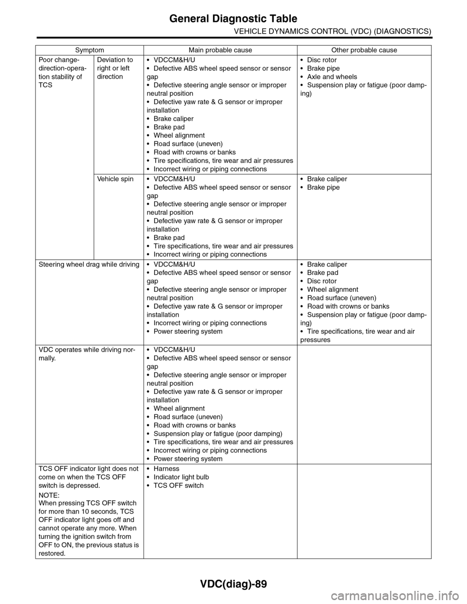
Po or ch a ng e -
direction-opera-
tion stability of
TCS
Deviation to
right or left
direction
•VDCCM&H/U
•Defective ABS wheel speed sensor or sensor
gap
•Defective steering angle sensor or improper
neutral position
•Defective yaw rate & G sensor or improper
installation
•Brake caliper
•Brake pad
•Wheel alignment
•Road surface (uneven)
•Road with crowns or banks
•Tire specifications, tire wear and air pressures
•Incorrect wiring or piping connections
•Disc rotor
•Brake pipe
•Axle and wheels
•Suspension play or fatigue (poor damp-
ing)
Ve h i c l e s p i n • V D C C M & H / U
•Defective ABS wheel speed sensor or sensor
gap
•Defective steering angle sensor or improper
neutral position
•Defective yaw rate & G sensor or improper
installation
•Brake pad
•Tire specifications, tire wear and air pressures
•Incorrect wiring or piping connections
•Brake caliper
•Brake pipe
Steering wheel drag while driving • VDCCM&H/U
•Defective ABS wheel speed sensor or sensor
gap
•Defective steering angle sensor or improper
neutral position
•Defective yaw rate & G sensor or improper
installation
•Incorrect wiring or piping connections
•Power steering system
•Brake caliper
•Brake pad
•Disc rotor
•Wheel alignment
•Road surface (uneven)
•Road with crowns or banks
•Suspension play or fatigue (poor damp-
ing)
•Tire specifications, tire wear and air
pressures
VDC operates while driving nor-
mally.
•VDCCM&H/U
•Defective ABS wheel speed sensor or sensor
gap
•Defective steering angle sensor or improper
neutral position
•Defective yaw rate & G sensor or improper
installation
•Wheel alignment
•Road surface (uneven)
•Road with crowns or banks
•Suspension play or fatigue (poor damping)
•Tire specifications, tire wear and air pressures
•Incorrect wiring or piping connections
•Power steering system
TCS OFF indicator light does not
come on when the TCS OFF
switch is depressed.
NOTE:When pressing TCS OFF switch
for more than 10 seconds, TCS
OFF indicator light goes off and
cannot operate any more. When
turning the ignition switch from
OFF to ON, the previous status is
restored.
•Harness
•Indicator light bulb
•TCS OFF switch
Symptom Main probable cause Other probable cause
Page 1092 of 2453
VDC-11
VDC Control Module & Hydraulic Control Unit (VDCCM&H/U)
VEHICLE DYNAMICS CONTROL (VDC)
D: ADJUSTMENT
When the following replacement, removal and in-
stallation are performed, be sure to perform center-
ing of the steering angle sensor and zero point
setting of the yaw rate & G sensor.
•VDCCM&H/U
•Steering angle sensor
•Yaw rate & lateral G sensor
•Steering wheel parts (Including airbag)
•Suspension parts
•Wheel alignment adjustment
1) Park the vehicle straight on a level surface. (En-
gine operation in the “P” or “N” range)
2) Check that steering wheel is positioned at the
center. (When the center position is not correct, ad-
just the wheel alignment.)
3) Set the Subaru Select Monitor to the vehicle,
and select {Set up mode for Neutral of Steering An-
gle Sensor & Lateral G Sensor 0 point} in the
“Function check sequence” screen. (Follow the
procedures shown in the display.)
4) On the “Brake Control System” display screen,
select {Current Data Display & Save}, and check
that the steering angle sensor shows “0 deg”.
5) When the “0 deg” is not displayed, repeat the
above steps and check that the “0 deg” is dis-
played.
6) Drive the vehicle for 10 minutes, and check that
the ABS and VDC warning light is not illuminated.
7) Check that there is no unnecessary VDC opera-
tion or steering control loss. If there is a problem,
repeat the steps above.
Page 1100 of 2453
VDC-19
Steering Angle Sensor
VEHICLE DYNAMICS CONTROL (VDC)
6. Steering Angle Sensor
A: REPLACEMENT
CAUTION:
•Do not perform the removal except when the
replacement.
•When replacing more than three times, re-
place the combination switch as assembly to
protect the threads.
1) Set the steering wheel in a straight-ahead posi-
tion.
2) Disconnect the ground cable from the battery.
3) Remove the airbag module.
WARNING:
Always refer to “Airbag System” when perform-
ing the airbag module repair service.
4) Remove the steering wheel.
5) Remove the screws and remove the steering
column lower cover.
6) Remove the two screws securing the steering
column upper cover.
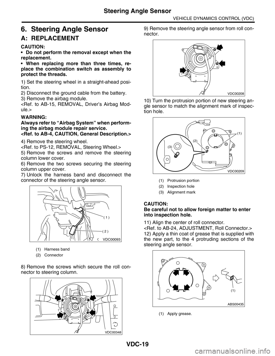
7) Unlock the harness band and disconnect the
connector of the steering angle sensor.
8) Remove the screws which secure the roll con-
nector to steering column.
9) Remove the steering angle sensor from roll con-
nector.
10) Turn the protrusion portion of new steering an-
gle sensor to match the alignment mark of inspec-
tion hole.
CAUTION:
Be careful not to allow foreign matter to enter
into inspection hole.
11) Align the center of roll connector.
12) Apply a thin coat of grease that is supplied with
the new part, to the 4 protruding sections of the
steering angle sensor.
(1) Harness band
(2) Connector
VDC00093
( 1 )
( 2 )
VDC00348
(1) Protrusion portion
(2) Inspection hole
(3) Alignment mark
(1) Apply grease.
VDC00208
VDC00209
(1)
(2)
(3)
ABS00435
(1)
Page 1101 of 2453
VDC-20
Steering Angle Sensor
VEHICLE DYNAMICS CONTROL (VDC)
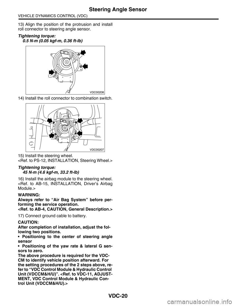
13) Align the position of the protrusion and install
roll connector to steering angle sensor.
Tightening torque:
0.5 N·m (0.05 kgf-m, 0.36 ft-lb)
14) Install the roll connector to combination switch.
15) Install the steering wheel.
Tightening torque:
45 N·m (4.6 kgf-m, 33.2 ft-lb)
16) Install the airbag module to the steering wheel.
WARNING:
Always refer to “Air Bag System” before per-
forming the service operation.
17) Connect ground cable to battery.
CAUTION:
After completion of installation, adjust the fol-
lowing two positions.
•Positioning to the center of steering angle
sensor
•Positioning of the yaw rate & lateral G sen-
sors to zero.
The above procedure is required for the VDC-
CM to identify vehicle position afterward. For
the setting procedures of the 2 steps above, re-
fer to “VDC Control Module & Hydraulic Control
Unit (VDCCM&H/U)”.
trol Unit (VDCCM&H/U).>
VDC00208
VDC00207
Page 1102 of 2453
VDC-21
Front ABS Wheel Speed Sensor
VEHICLE DYNAMICS CONTROL (VDC)
7. Front ABS Wheel Speed Sen-
sor
A: REMOVAL
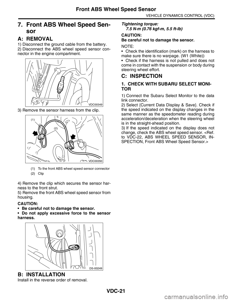
1) Disconnect the ground cable from the battery.
2) Disconnect the ABS wheel speed sensor con-
nector in the engine compartment.
3) Remove the sensor harness from the clip.
4) Remove the clip which secures the sensor har-
ness to the front strut.
5) Remove the front ABS wheel speed sensor from
housing.
CAUTION:
•Be careful not to damage the sensor.
•Do not apply excessive force to the sensor
harness.
B: INSTALLATION
Install in the reverse order of removal.
Tightening torque:
7.5 N·m (0.76 kgf-m, 5.5 ft-lb)
CAUTION:
Be careful not to damage the sensor.
NOTE:
•Check the identification (mark) on the harness to
make sure there is no warpage. (W1 (White))
•Check if the harness is not pulled and does not
come in contact with the suspension or body during
steering wheel effort.
C: INSPECTION
1. CHECK WITH SUBARU SELECT MONI-
TOR
1) Connect the Subaru Select Monitor to the data
link connector.
2) Select {Current Data Display & Save}. Check if
the speed indicated on the display changes in the
same manner as the speedometer reading during
acceleration/deceleration when the steering wheel
is in the straight-ahead position.
3) If the speed indicated on the display does not
change, check the ABS wheel speed sensor.
SPECTION, Front ABS Wheel Speed Sensor.>
(1) To the front ABS wheel speed sensor connector
(2) Clip
VDC00349
VDC00350
(1)
(2)
DS-00249