2009 SUBARU TRIBECA keyless
[x] Cancel search: keylessPage 679 of 2453

SL-50
Keyless Entry Control Module
SECURITY AND LOCKS
21.Keyless Entry Control Module
A: REMOVAL
1) Disconnect the ground cable from battery.
2) Remove the glove box.
3) Remove the nut, then disconnect the connector
to remove the keyless entry control module.
B: INSTALLATION
Install in the reverse order of removal.
SL-00456
Page 680 of 2453

SL-51
Keyless Buzzer
SECURITY AND LOCKS
22.Keyless Buzzer
A: REMOVAL
1) Disconnect the ground cable from battery.
2) Remove the keyless buzzer installed to the
backside of radiator bracket.
B: INSTALLATION
Install in the reverse order of removal.
C: INSPECTION
Install the keyless buzzer to another vehicle which
operates keyless buzzer normally, check the buzz-
er sounds. If NG, replace the keyless buzzer.
Page 682 of 2453

SL-53
Transmitter
SECURITY AND LOCKS
24.Transmitter
A: REMOVAL
1. TRANSMITTER BATTERY
Remove the battery (1) from the transmitter.
NOTE:
To prevent static electricity damage to the transmit-
ter printed circuit board, touch the steel area of
building with hand to discharge static electricity car-
ried on body or clothes before disassembling the
transmitter.
B: INSTALLATION
1. TRANSMITTER BATTERY
Install in the reverse order of removal.
C: INSPECTION
1. TRANSMITTER BATTERY
Measure the voltage between the keyless transmit-
ter battery (+) terminal and (-) terminal.
NOTE:
Battery discharge occurs during the measurement.
Complete the measurement within 5 seconds.
If NG, replace the battery. (Use CR2025 or equiva-
lent.)
D: REPLACEMENT
1. REGISTRATION OF KEYLESS TRANS-
MITTER WITH SUBARU SELECT MONITOR
NOTE:
•A maximum of four keyless transmitter can be
registered for each individual vehicle.
•When replacing or adding the keyless transmit-
ter, new registration of transmitter is necessary.
1) Connect the Subaru Select Monitor to the vehi-
cle.
2) Turn the ignition switch to ON.
3) From the «Main menu» on the Subaru Select
Monitor, select the {2. Check individual system} →
{7. Integrated unit mode} → {8. Transmitter ID reg-
istration}, and press the [YES] key.
4) Input the 8-digit ID number fund inside the plas-
tic bag that the transmitter came in, or inside the
transmitter, from left to right. Press the [YES] key.
NOTE:
Press the [ ] key on the Subaru Select Monitor to
increase the number, and the [ ] key to decrease.
Press the [<] key to move to the digit in the left, and
[>] to the right.
5) The ID number you have entered will be shown.
Make sure that the ID number shown is the same
as that of plastic bag.
6) Press the [YES] key if the ID number is correct.
Press the [NO] key if incorrect, to return to the step
3) and try again.
7) «ID registration in process···» is displayed and
registration starts.
8) »ID registration done» will be displayed when
the registration process is done.
9) To exit, select «END:NO», and press the [NO]
key to return to {8. Transmitter ID registration}. If
there are additional transmitters to be registered,
select «Next registration:YES», and press the
[YES] key to return to the step 3).
NOTE:
•If the registration fails, «ID registration failed. Try
again.» will be shown. Press the [YES] key to re-
turn to the {8. Transmitter ID registration}. Retry
from step 2.
•«END: NO» is shown on the Subaru Select Mon-
itor when fourth keyless transmitter has been regis-
tered. Press the [NO] key to return to {8.
Transmitter ID registration}.(A) Resistance (47 Ω)
Te s t e r c o n n e c t i o n
(+) (–) Standard
Battery
Po si t ive t e r mi na l
Battery
Ground terminal2.5 — 3.0 V
(1)
SL-00387
SL-00066
(A)
Page 2304 of 2453
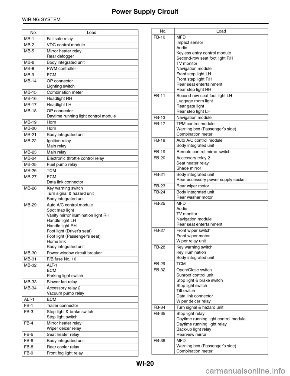
WI-20
Power Supply Circuit
WIRING SYSTEM
No. Load
MB-1 Fail safe relay
MB-2 VDC control module
MB-5 Mirror heater relay
Rear defogger
MB-6 Body integrated unit
MB-8 PWM controller
MB-9 ECM
MB-14 OP connector
Lighting switch
MB-15 Combination meter
MB-16 Headlight RH
MB-17 Headlight LH
MB-18 OP connector
Daytime running light control module
MB-19 Horn
MB-20 Horn
MB-21 Body integrated unit
MB-22 Ignition relay
Main relay
MB-23 Main relay
MB-24 Electronic throttle control relay
MB-25 Fuel pump relay
MB-26 TCM
MB-27 ECM
Data link connector
MB-28 Key warning switch
Tu r n s i g n a l & h a z a r d u n i t
Body integrated unit
MB-29 Auto A/C control module
Spot map light
Va n i t y m i r r o r i l l u m i n a t i o n l i g h t R H
Handle light LH
Handle light RH
Foot light (Driver’s seat)
Foot light (Passenger’s seat)
Home link
Body integrated unit
MB-30 Power window circuit breaker
MB-31 F/B fuse No. 16
MB-32 ALT-1
ECM
Par king light switch
MB-33 Blower fan relay
MB-34 Accessory relay 2
Va c u u m p u m p r e l ay
ALT-1 ECM
FB-1 Trailer connector
FB-3 Stop light & brake switch
Stop light switch
FB-4 Mirror heater relay
Wiper deicer relay
FB-5 Seat heater relay
FB-6 Body integrated unit
FB-8 Rear cooler relay
FB-9 Front fog light relay
FB-10 MFD
Impact sensor
Audio
Keyless entr y control module
Second-row seat foot light RH
TV monitor
Navigation module
Fr o n t s te p li gh t LH
Fr o n t s te p li gh t RH
Rear seat entertainment
Rear step light RH
FB-11 Second-row seat foot light LH
Luggage room light
Rear gate light
Rear step light LH
FB-13 Navigation module
FB-17 TPM control module
War ning box (Passenger’s side)
Combination meter
FB-18 Auto A/C control module
Body integrated unit
FB-19 Remote control mirror switch
FB-20 Accessory relay 2
Seat heater relay
Shade mirror
FB-21 Body integrated unit
Rear accessory power supply socket
FB-23 Rear wiper motor
FB-24 Body integrated unit
Rear washer motor
FB-25 MFD
Audio
TV monitor
Navigation module
Rear seat entertainment
FB-27 Front wiper switch
Fr o n t wi p er mo t or
Wiper relay unit
FB-28 Key warning switch
Key illumination
Body integrated unit
FB-29 TCM
FB-32 Open/Close switch
Sunroof control unit
Stop light & brake switch
Stop light switch
Tilt switch
Data link connector
Wiper deicer relay
FB-34 Turn signal & hazard unit
FB-35 Stop light relay
Daytime running light control module
Daytime running light relay
Back-up light relay
Rearview mirror
FB-36 MFD
War ning box (Passenger’s side)
Combination meter
No. Load
Page 2306 of 2453
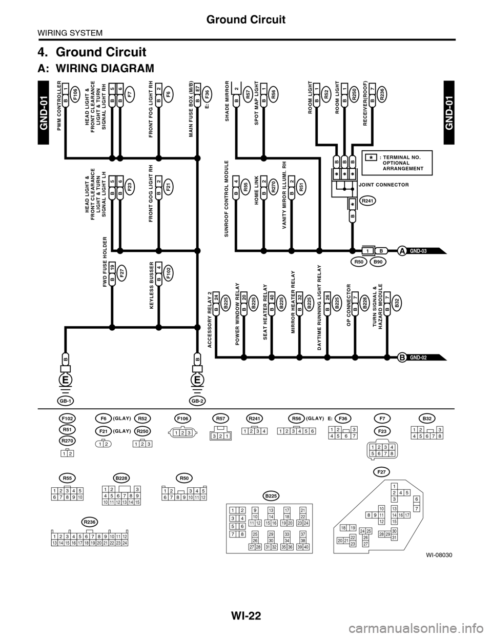
WI-22
Ground Circuit
WIRING SYSTEM
4. Ground Circuit
A: WIRING DIAGRAM
WI-08030
GND-01GND-01
F106B1
PWM CONTROLLER
F6(GLAY)(GLAY)
(GLAY)
F102
R270
F21
F7F6B2
FRONT FOG LIGHT RH
E:
F36B E7
MAIN FUSE BOX (M/B)
R55B4R51B2
VANITY MIROR ILLUMI. RH
R270B2
HOME LINK
R52B1
1
ROOM LIGHT
R250R57B1
ROOM LIGHT
R236B7
RECEIVER(ROOF)SHADE MIRROR
B225B 26
DAYTIME RUNNING LIGHT RELAY
F27B 19FWD FUSE HOLDER
F102B4
KEYLESS BUSSERB225B 24
ACCESSORY RELAY 2
B225B 40
SEAT HEATER RELAY
B225B 20
POWER WINDOW RELAY
B228B7
OP CONNECTOR
B32B7
TURN SIGNAL &HAZARD MODULE
B225B 32
MIRROR HEATER RELAY
GND-02B
GB-1
B
GB-2
B
B
12
12
R52
R250
123
F7
F23
R57
B228
131415
123456789101112
F27
13141516 17
27
24 252620 212223
29303128
89101112
12534
7
6
1918
B225
13141516
17
27
24
2526
20
212223
293031283235
33343738393640
8
9101112
12
534
761918
B32
12345678
SUNROOF CONTROL MODULE
HEAD LIGHT &FRONT CLEARANCELIGHT & TURNSIGNAL LIGHT RH
GND-03A
R51
234510 111678912
R50
F106
123
B A16B5B6
F23F21B2
FRONT GOG LIGHT RH
HEAD LIGHT &FRONT CLEARANCELIGHT & TURNSIGNAL LIGHT LH
B A16B5B6
R56B
SPOT MAP LIGHT
JOINT CONNECTOR
R241
***
*
B90R50
B
B
BBB
1
*: TERMINAL NO. OPTIONAL ARRANGEMENT
123
R56
1234561234567
F36E:
R55
12346789510
R241
1234
R236
123 8910413 14 15 1656711121718192021222324
2
34561278
Page 2309 of 2453
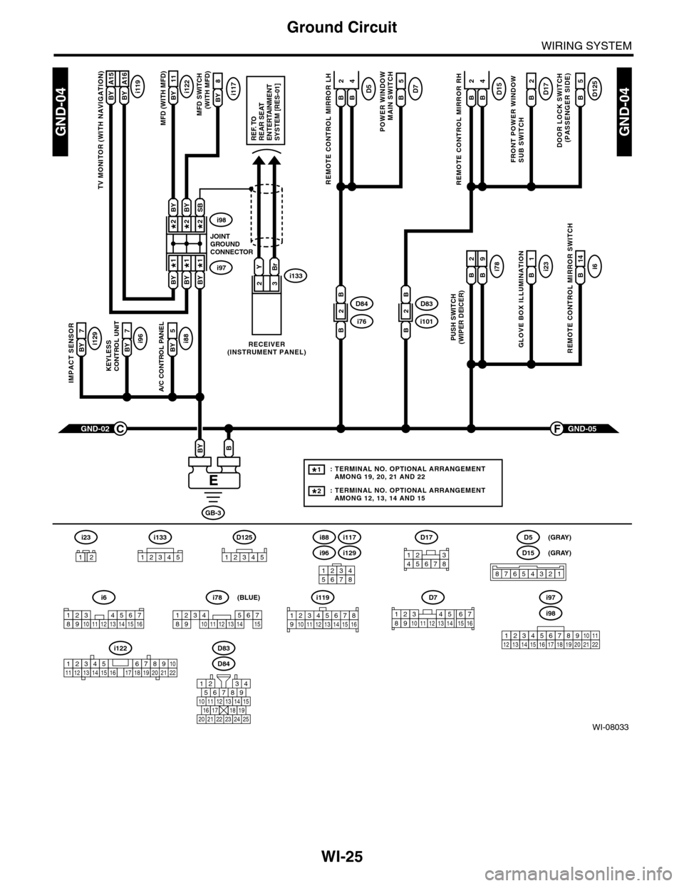
WI-25
Ground Circuit
WIRING SYSTEM
WI-08033
GND-04GND-04
i117BYi122BY 11
8
A/C CONTROL PANEL
i88BY 5
23
GND-05F
KEYLESS CONTROL UNIT
i96BY 7
IMPACT SENSOR
i129BY 7
TV MONITOR (WITH NAVIGATION)
i119BY A15BY A16
GND-02C
GB-3
BBY
D83
MFD (WITH MFD)MFD SWITCH (WITH MFD)
i96
12345678
i6
42
14
REMOTE CONTROL MIRROR SWITCH
i97i133
i98
JOINTGROUNDCONNECTOR
RECEIVER(INSTRUMENT PANEL)
2*2*
1*1*
2*
1*
BYBi231
GLOVE BOX ILLUMINATION
Bi789
PUSH SWITCH(WIPER DEICER)
B
2
BBYBY
SBBYBY
YBr
REF. TOREAR SEATENTERTAINMENT SYSTEM [RES-01]
: TERMINAL NO. OPTIONAL ARRANGEMENT AMONG 19, 20, 21 AND 22
: TERMINAL NO. OPTIONAL ARRANGEMENT AMONG 12, 13, 14 AND 15
1*
2*
D125
5
DOOR LOCK SWITCH(PASSENGER SIDE)
BD17
2
FRONT POWER WINDOW SUB SWITCH
POWER WINDOW
MAIN SWITCH
BD75
BD15
REMOTE CONTROL MIRROR RH
BB
42D5
REMOTE CONTROL MIRROR LH
BB
i1012D83
B
B
i762D84
B
B
D84
i88
i129
i117
567821943
10
2422 23 25
1112131415161718192021
i98
i97
12345678910111213141516171819202122
D7
12345689101112131514716
D17
12345678
D5
D15
87654321
(GRAY)
(GRAY)
i6
12345678910111213141516
i119
123 8910412 13 14 15 1656711
i133
12345
12345678910111213141516171819202122
i122
i78
123456789101112131415
(BLUE)
i23
12
D125
12345
Page 2424 of 2453
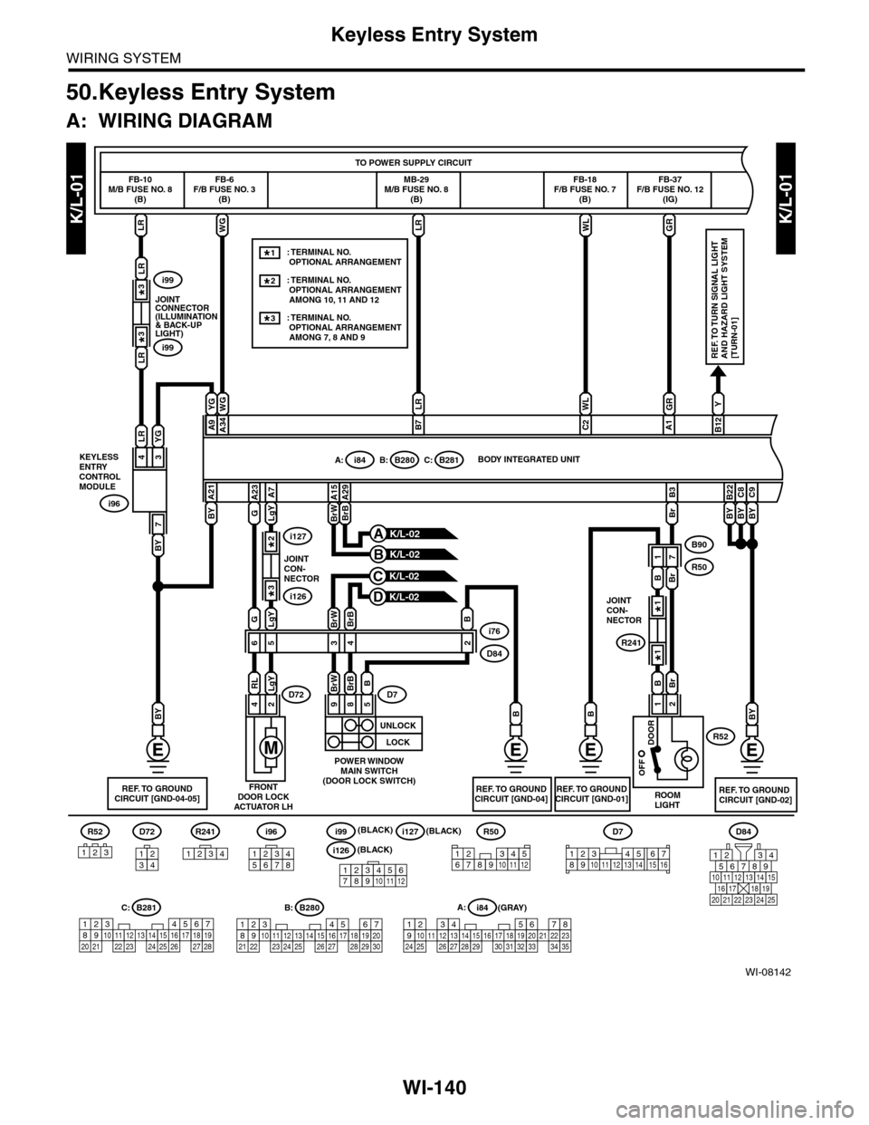
WI-140
Keyless Entry System
WIRING SYSTEM
50.Keyless Entry System
A: WIRING DIAGRAM
K/L-01K/L-01
WI-08142
i96
123456781234
D72
56782194310242223 25111213141526 27 281617181920 21
B281C:A:i84
1234567891011121415161718192021222324252627282930313233343513
BY
LR
LR
i99
i99
7
BY
43
YGLR
i96
LRLRWLGR
BY
BY
GRWL
C8
BY
B22
BY
C9
Y
B12
LR
A1C2
A:i84B:B280C:B281
WG
D84
567821943
10
2422 23 25
11121314151617181920 21
YG
A9
BY
A21
WG
A34B7
5467821931022 23111213141524 25 26 2716171828 29192021 30
B280B:
GLgY
56
24
RLLgYD72
G
A23
LgY
A7
B90
R50
43
89
BrWBrB
BrWBrB
BrW
A15
BrB
A29
5
BD7
2
B
BB1
BBr
BrB
R52
71
Br
B3
i76
D84
R50
123456789101112
R52
321
K/L-02C
K/L-02B
K/L-02A
K/L-02D
FB-10M/B FUSE NO. 8(B)
JOINTCONNECTOR(ILLUMINATION& BACK-UPLIGHT)
KEYLESSENTRYCONTROLMODULE
FB-6F/B FUSE NO. 3(B)
MB-29M/B FUSE NO. 8(B)
FB-18F/B FUSE NO. 7(B)
FB-37F/B FUSE NO. 12(IG)
TO POWER SUPPLY CIRCUIT
BODY INTEGRATED UNIT
REF. TO TURN SIGNAL LIGHTAND HAZARD LIGHT SYSTEM[TURN-01]
REF. TO GROUNDCIRCUIT [GND-02]REF. TO GROUNDCIRCUIT [GND-04-05]FRONTDOOR LOCKACTUATOR LH
REF. TO GROUNDCIRCUIT [GND-04]REF. TO GROUNDCIRCUIT [GND-01]
POWER WINDOWMAIN SWITCH(DOOR LOCK SWITCH)
ROOMLIGHT
i126
i127
JOINTCON-NECTOR
2*
3*
R241
JOINTCON-NECTOR
1*
1*
3*
3*
: TERMINAL NO. OPTIONAL ARRANGEMENT : TERMINAL NO. OPTIONAL ARRANGEMENT AMONG 10, 11 AND 12
1*
2*
: TERMINAL NO. OPTIONAL ARRANGEMENT AMONG 7, 8 AND 9
3*
D7
12345689101112131514716123456789101112
i127(BLACK)
(GRAY)
i126(BLACK)
i99R241(BLACK)
1234
UNLOCK
LOCK
OFF
DOOR
2
Page 2425 of 2453
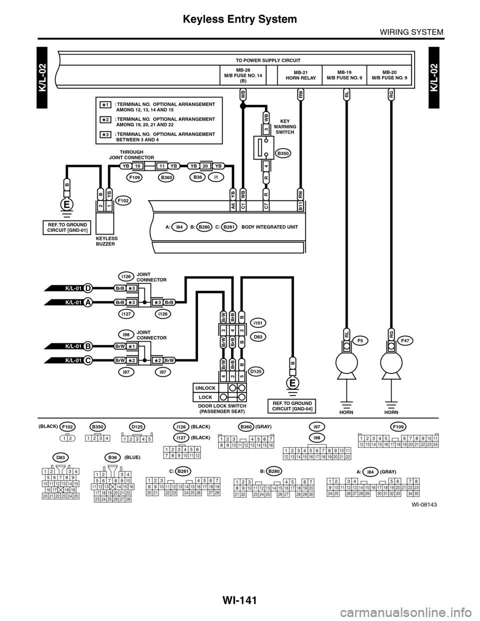
WI-141
Keyless Entry System
WIRING SYSTEM
K/L-02K/L-02
WI-08143
F5F47
RGRL
RW
B11
B: B280
RW
RGRL
5467821931022 23111213141524 25 26 2716171828 29192021 30
B280B:
D125
B
i101
D83
D125
12345
D83
567821943
10
2422 23 25
11121314151617181920 21
K/L-01B
K/L-01C
B350
WB
3
R
4
WB
R
C7
WB
C1F102
B360F109i1B36
2
B
19
1
YB
YBYBYB2011
B350
1234
F102
12
F109
3412 8910 1112 13 14 15 16 17 18 19 20 21 22 23 24567
56782194310
242223 252726 28
11121314151617181920 21
567821943102422 23 25111213141526 27 281617181920 21
B281C:A:i84
1234567891011121415161718192021222324252627282930313233343513
YB
YB
A6
A: i84C: B281
HORN HORN
TO POWER SUPPLY CIRCUIT
MB-19M/B FUSE NO. 9MB-20M/B FUSE NO. 9
BODY INTEGRATED UNIT
MB-21HORN RELAY
REF. TO GROUNDCIRCUIT [GND-04]DOOR LOCK SWITCH(PASSENGER SEAT)
i97i97
i98JOINTCONNECTOR
KEYLESSBUZZER
THROUGHJOINT CONNECTOR
KEYWARNINGSWITCH
MB-28M/B FUSE NO. 14(B)
(GRAY)
(GRAY)
B360
12345678910111213141516
BrW
BrW
BrW2*
1*
2*
K/L-01D
K/L-01A
i127i126
i126JOINTCONNECTOR
BrB
BrB
BrB3*
3*
3*
B
REF. TO GROUNDCIRCUIT [GND-01]
123456789101112
i127(BLACK)
(BLACK)i126(BLACK)
B36(BLUE)
i98
i97
12345678910111213141516171819202122
: TERMINAL NO. OPTIONAL ARRANGEMENT AMONG 12, 13, 14 AND 15
: TERMINAL NO. OPTIONAL ARRANGEMENT AMONG 19, 20, 21 AND 22
1*
2*
: TERMINAL NO. OPTIONAL ARRANGEMENT BETWEEN 3 AND 43*
24
BrWBrB
5
B
BrWBrBB
BrWBrBB
UNLOCK
LOCK
432